EP0861992A1 - Joint universel homocitétique - Google Patents
Joint universel homocitétique Download PDFInfo
- Publication number
- EP0861992A1 EP0861992A1 EP98102222A EP98102222A EP0861992A1 EP 0861992 A1 EP0861992 A1 EP 0861992A1 EP 98102222 A EP98102222 A EP 98102222A EP 98102222 A EP98102222 A EP 98102222A EP 0861992 A1 EP0861992 A1 EP 0861992A1
- Authority
- EP
- European Patent Office
- Prior art keywords
- universal joint
- constant velocity
- velocity universal
- holder
- joint according
- Prior art date
- Legal status (The legal status is an assumption and is not a legal conclusion. Google has not performed a legal analysis and makes no representation as to the accuracy of the status listed.)
- Granted
Links
Images


Classifications
-
- F—MECHANICAL ENGINEERING; LIGHTING; HEATING; WEAPONS; BLASTING
- F16—ENGINEERING ELEMENTS AND UNITS; GENERAL MEASURES FOR PRODUCING AND MAINTAINING EFFECTIVE FUNCTIONING OF MACHINES OR INSTALLATIONS; THERMAL INSULATION IN GENERAL
- F16D—COUPLINGS FOR TRANSMITTING ROTATION; CLUTCHES; BRAKES
- F16D3/00—Yielding couplings, i.e. with means permitting movement between the connected parts during the drive
- F16D3/16—Universal joints in which flexibility is produced by means of pivots or sliding or rolling connecting parts
- F16D3/20—Universal joints in which flexibility is produced by means of pivots or sliding or rolling connecting parts one coupling part entering a sleeve of the other coupling part and connected thereto by sliding or rolling members
- F16D3/202—Universal joints in which flexibility is produced by means of pivots or sliding or rolling connecting parts one coupling part entering a sleeve of the other coupling part and connected thereto by sliding or rolling members one coupling part having radially projecting pins, e.g. tripod joints
- F16D3/205—Universal joints in which flexibility is produced by means of pivots or sliding or rolling connecting parts one coupling part entering a sleeve of the other coupling part and connected thereto by sliding or rolling members one coupling part having radially projecting pins, e.g. tripod joints the pins extending radially outwardly from the coupling part
- F16D3/2055—Universal joints in which flexibility is produced by means of pivots or sliding or rolling connecting parts one coupling part entering a sleeve of the other coupling part and connected thereto by sliding or rolling members one coupling part having radially projecting pins, e.g. tripod joints the pins extending radially outwardly from the coupling part having three pins, i.e. true tripod joints
-
- F—MECHANICAL ENGINEERING; LIGHTING; HEATING; WEAPONS; BLASTING
- F16—ENGINEERING ELEMENTS AND UNITS; GENERAL MEASURES FOR PRODUCING AND MAINTAINING EFFECTIVE FUNCTIONING OF MACHINES OR INSTALLATIONS; THERMAL INSULATION IN GENERAL
- F16D—COUPLINGS FOR TRANSMITTING ROTATION; CLUTCHES; BRAKES
- F16D3/00—Yielding couplings, i.e. with means permitting movement between the connected parts during the drive
- F16D3/16—Universal joints in which flexibility is produced by means of pivots or sliding or rolling connecting parts
- F16D3/20—Universal joints in which flexibility is produced by means of pivots or sliding or rolling connecting parts one coupling part entering a sleeve of the other coupling part and connected thereto by sliding or rolling members
- F16D3/202—Universal joints in which flexibility is produced by means of pivots or sliding or rolling connecting parts one coupling part entering a sleeve of the other coupling part and connected thereto by sliding or rolling members one coupling part having radially projecting pins, e.g. tripod joints
- F16D3/205—Universal joints in which flexibility is produced by means of pivots or sliding or rolling connecting parts one coupling part entering a sleeve of the other coupling part and connected thereto by sliding or rolling members one coupling part having radially projecting pins, e.g. tripod joints the pins extending radially outwardly from the coupling part
- F16D3/2052—Universal joints in which flexibility is produced by means of pivots or sliding or rolling connecting parts one coupling part entering a sleeve of the other coupling part and connected thereto by sliding or rolling members one coupling part having radially projecting pins, e.g. tripod joints the pins extending radially outwardly from the coupling part having two pins
-
- F—MECHANICAL ENGINEERING; LIGHTING; HEATING; WEAPONS; BLASTING
- F16—ENGINEERING ELEMENTS AND UNITS; GENERAL MEASURES FOR PRODUCING AND MAINTAINING EFFECTIVE FUNCTIONING OF MACHINES OR INSTALLATIONS; THERMAL INSULATION IN GENERAL
- F16D—COUPLINGS FOR TRANSMITTING ROTATION; CLUTCHES; BRAKES
- F16D3/00—Yielding couplings, i.e. with means permitting movement between the connected parts during the drive
- F16D3/16—Universal joints in which flexibility is produced by means of pivots or sliding or rolling connecting parts
- F16D3/20—Universal joints in which flexibility is produced by means of pivots or sliding or rolling connecting parts one coupling part entering a sleeve of the other coupling part and connected thereto by sliding or rolling members
- F16D3/202—Universal joints in which flexibility is produced by means of pivots or sliding or rolling connecting parts one coupling part entering a sleeve of the other coupling part and connected thereto by sliding or rolling members one coupling part having radially projecting pins, e.g. tripod joints
- F16D2003/2023—Universal joints in which flexibility is produced by means of pivots or sliding or rolling connecting parts one coupling part entering a sleeve of the other coupling part and connected thereto by sliding or rolling members one coupling part having radially projecting pins, e.g. tripod joints with linear rolling bearings between raceway and trunnion mounted shoes
-
- Y—GENERAL TAGGING OF NEW TECHNOLOGICAL DEVELOPMENTS; GENERAL TAGGING OF CROSS-SECTIONAL TECHNOLOGIES SPANNING OVER SEVERAL SECTIONS OF THE IPC; TECHNICAL SUBJECTS COVERED BY FORMER USPC CROSS-REFERENCE ART COLLECTIONS [XRACs] AND DIGESTS
- Y10—TECHNICAL SUBJECTS COVERED BY FORMER USPC
- Y10S—TECHNICAL SUBJECTS COVERED BY FORMER USPC CROSS-REFERENCE ART COLLECTIONS [XRACs] AND DIGESTS
- Y10S464/00—Rotary shafts, gudgeons, housings, and flexible couplings for rotary shafts
- Y10S464/904—Homokinetic coupling
- Y10S464/905—Torque transmitted via radially extending pin
Definitions
- the present invention relates to a constant velocity universal joint for coupling a driving shaft and a driven shaft, to be used, for example, for a driving force-transmitting section of an automobile.
- a constant velocity universal joint has been hitherto used for a driving force-transmitting section of an automobile in order to transmit a rotary power or a torque of a driving shaft to respective axles through a driven shaft.
- a constant velocity universal joint concerning the conventional technique is known, for example, as illustrated in FIG. 55, in which three track grooves 2 are formed along the axial direction on an inner surface of an outer wheel 1.
- Leg shafts 4, which protrude in the radial direction, are provided on a tripod member 3 which is arranged inside the outer wheel 1.
- a spherical roller 6 is fitted rotatably and slidably in the axial direction to an outer circumferential surface of each of the leg shafts 4 via a plurality of needle bearings 5.
- the spherical roller 6 is allowed to engage with a roller guide surface 7 disposed on both sides of the track groove 2.
- the lubrication failure causes formation of small holes on the surface of the spherical roller 6, i.e., so-called pits are generated.
- irregularities are formed on the surface of the spherical roller 6, i.e., so-called adhesive wear occurs.
- the spherical roller 6 intends to perform rolling motion in the direction indicated by an arrow A or an arrow B shown in FIG. 55, while the track groove 2 is cylindrical and it extends substantially in parallel to the axis of the outer wheel 1. Therefore, the spherical roller 6 is moved while being restricted by the track groove 2.
- a thrust force in the axial direction is induced by the slippage which is caused between the roller guide surface 7 of the track groove 2 and the spherical roller 6.
- the induced thrust force is increased in proportion to the increase of the angle of inclination of the tripod member 3 with respect to the outer wheel 1. It is feared to be difficult to smoothly transmit the rotary power of the driving shaft to the driven shaft.
- a frictional resistance is generated by the reciprocating motion effected by the spherical roller 6 along the roller guide surface 7.
- the induced thrust force refers to a load resulting from the frictional resistance.
- a constant velocity universal joint which is disclosed, for example, in Japanese Laid-Open Patent Publication No. 3-168416.
- this constant velocity universal joint three ball grooves are formed in the axial direction at the inside of an outer wheel. Three pairs of balls are held in the respective ball grooves by the aid of holders respectively.
- a tripod member is incorporated into the inside of the outer wheel. Three leg shafts extending in the radial direction, which are arranged between the adjacent pairs of balls, are provided on the tripod member. Each of the leg shafts is formed with a spherical surface.
- a ball guide which is formed with a spherical recess for engaging with the spherical surface, is provided between the spherical surface and the balls.
- a three-plane constant velocity joint is disclosed in Japanese Laid-Open Patent Publication No. 6-74243.
- an inner joint member is inserted into the inside of an outer joint member, and trunnions are provided on the inner joint member.
- Each of the trunnions is provided with a plurality of spherical balls.
- the spherical balls are constructed so that they are rollable along side walls which constitute a longitudinal chamber formed in the outer joint member.
- the spherical balls are held on the trunnion by the aid of a positioning spring installed to the trunnion.
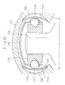
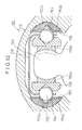
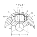
- FIG. 57 Another constant velocity universal joint concerning the conventional technique is known, which is constructed, for example, as illustrated in FIG. 57.
- a pair of track surfaces 2a, 2b which are opposed to one another and which have a circular arc-shaped cross-section, are formed in the axial direction on an inner wall surface of an outer joint member 1a.
- An inner joint member 3a which is disposed between the pair of track surfaces 2a, 2b, is arranged in an internal hollow space of the outer joint member 1a.
- a plurality of ball members 9 are provided rollably along the track surfaces 2a, 2b by the aid of a retainer 8 (see Japanese Patent Publication No. 7-74649).
- the constant velocity universal joint concerning the conventional technique involves the inconvenience that the durability and the vibration characteristics are deteriorated by any dimensional error depending on the machining accuracy for the pair of track surfaces 2a, 2b which are formed on the inner wall surface of the outer joint member 1 in the mutually opposing manner.
- the pair of track surfaces 2a, 2b of the outer joint member 1 on which the ball members 9 roll have a hardness not subjected to plasticization caused by the contact surface pressure generated between the track surfaces 2a, 2b and the ball members 9. For this reason, it is necessary to apply a heat treatment to the pair of track surfaces 2a, 2b, which results in an inconvenience that the production cost becomes expensive.
- a general object of the present invention is to provide a constant velocity universal joint which makes it possible to reduce the induced thrust force so that the driving force may be still more smoothly transmitted from one transmission shaft to the other transmission shaft.
- a principal object of the present invention is to provide a constant velocity universal joint which makes it possible to avoid occurrence of vibration in the direction of rotation and beat sound resulting from backlash even when the operating angle between one transmission shaft and the other transmission shaft is increased.
- Another object of the present invention is to provide a constant velocity universal joint which makes it possible to stabilize lubrication performance and avoid occurrence of pits and adhesive wear.
- Still another object of the present invention is to provide a constant velocity universal joint which makes it possible to shorten the assembling time and improve the operation efficiency by reliably holding ball members upon assembling without any disengagement of the ball members.
- Still another object of the present invention is to provide a constant velocity universal joint in which the spacing distance between a pair of mutually opposing rolling surfaces is not affected by any dimensional error.
- Still another object of the present invention is to provide a constant velocity universal joint which makes it possible to reduce the production cost by omitting the heat treatment step which would be otherwise required for rolling surfaces of an outer member.
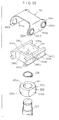
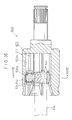
- FIG. 1 shows a longitudinal sectional view taken along an axial direction of a constant velocity universal joint according to a first embodiment of the present invention.
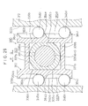
- FIG. 2 shows a sectional view taken along a line II-II shown in FIG. 1.
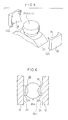
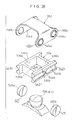
- FIG. 3 shows a perspective view illustrating a trunnion and a pair of slipper members engaging with the trunnion.
- FIG. 4A to 4C show longitudinal sectional views illustrating modified embodiments of the slipper member shown in FIG. 3.
- FIG. 5 shows a perspective view illustrating a modified embodiment of the slipper member shown in FIG. 3.
- FIG. 6 shows a sectional view taken along a line VI-VI shown in FIG. 2.
- FIGs. 7A and 7B illustrate the relationship between the angle of inclination of the second shaft and the induced thrust force.
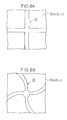
- FIGs. 8A and 8B illustrate shapes of lubricating grooves formed on outer surfaces of the trunnions respectively.
- FIG. 9 shows a cross-sectional view, with partial omission, illustrating lubricating grooves formed on sliding surfaces of a guide groove.
- FIG. 10 shows a cross-sectional view illustrating application of the constant velocity universal joint shown in FIG. 2 to a bipod type.
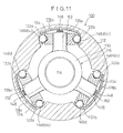
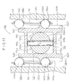
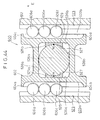
- FIG. 11 shows a cross-sectional view illustrating a constant velocity universal joint according to a second embodiment of the present invention.
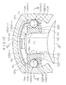
- FIG. 12 shows a partial magnified view illustrating the constant velocity universal joint shown in FIG. 11.
- FIG. 13 shows a sectional view taken along a line XIII-XIII shown in FIG. 12.
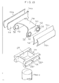
- FIG. 14 shows a partial exploded perspective view illustrating the constant velocity universal joint shown in FIG. 12.
- FIG. 15 shows a sectional view taken along a line XV-XV shown in FIG. 12.
- FIG. 16 shows a partial magnified sectional view illustrating a constant velocity universal joint according to a third embodiment of the present invention.
- FIG. 17 shows a sectional view taken along a line XVII-XVII shown in FIG. 16.
- FIG. 18 shows a partial magnified sectional view illustrating a constant velocity universal joint according to a fourth embodiment of the present invention.
- FIG. 19 shows a partial magnified sectional view illustrating a constant velocity universal joint according to a fifth embodiment of the present invention.
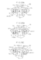
- FIGs. 20A to 20C illustrate the operation depicting the state in which the holder makes follow-up displacement with respect to the trunnion in the constant velocity universal joint shown in FIG. 11 respectively.
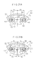
- FIGs. 21A and 21B illustrate the operation based on the use of Comparative Example of a constant velocity universal joint respectively.
- FIG. 22 shows a cross-sectional view illustrating application of the constant velocity universal joint shown in FIG. 11 to a bipod type.
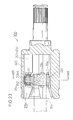
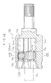
- FIG. 23 shows a longitudinal sectional view taken along an axial direction of a constant velocity universal joint according to a sixth embodiment of the present invention.
- FIG. 24 shows a sectional view taken along a line XXIV-XXIV shown in FIG. 23.
- FIG. 25 shows a partial magnified view illustrating the constant velocity universal joint shown in FIG. 24.
- FIG. 26 shows a partial magnified exploded perspective view illustrating the constant velocity universal joint shown in FIG. 24.
- FIG. 27 shows a sectional view taken along a line XXVII-XXVII shown in FIG. 25.
- FIG. 28 shows a sectional view taken along a line XXVIII-XXVIII shown in FIG. 25.
- FIG. 29 shows a sectional view illustrating a constant velocity universal joint according to a seventh embodiment of the present invention.
- FIG. 30 shows a sectional view illustrating a constant velocity universal joint according to an eighth embodiment of the present invention.
- FIGs. 31A to 31C illustrate methods for fastening the slipper member for constructing the constant velocity universal joint shown in FIG. 23.
- FIGs. 32A to 32C illustrate the operation depicting the state in which the holder makes follow-up displacement with respect to the trunnion in the constant velocity universal joint shown in FIG. 23 respectively.
- FIGs. 33A and 33B illustrate the operation based on the use of Comparative Example of a constant velocity universal joint respectively.
- FIG. 34 shows a cross-sectional view illustrating application of the constant velocity universal joint shown in FIG. 24 to a bipod type.
- FIG. 35 shows a longitudinal sectional view taken along an axial direction of a constant velocity universal joint according to a ninth embodiment of the present invention.
- FIG. 36 shows a sectional view taken along a line XXXVI-XXXVI shown in FIG. 35.
- FIG. 37 shows a partial magnified view illustrating the constant velocity universal joint shown in FIG. 36.
- FIG. 38 shows a partial magnified exploded perspective view illustrating the constant velocity universal joint shown in FIG. 36.
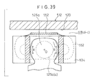
- FIG. 39 shows a sectional view taken along a line XXXIX-XXXIX shown in FIG. 37.
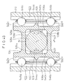
- FIG. 40 shows a sectional view taken along a line XL-XL shown in FIG. 37.
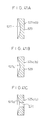
- FIGs. 41A to 41C show longitudinal sectional views illustrating modified embodiments of the slipper member for constructing the constant velocity universal joint shown in FIG. 35.
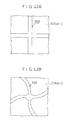
- FIGs. 42A and 42B illustrate lubricating grooves formed on the trunnion for constructing the constant velocity universal joint shown in FIG. 35 respectively.
- FIG. 43 shows a sectional view illustrating a constant velocity universal joint according to a tenth embodiment of the present invention.
- FIG. 44 shows a sectional view illustrating a constant velocity universal joint according to an eleventh embodiment of the present invention.
- FIG. 45 shows a longitudinal sectional view illustrating application of the constant velocity universal joint shown in FIG. 36 to a bipod type.
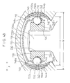
- FIG. 46 shows a longitudinal sectional view illustrating a constant velocity universal joint according to a twelfth embodiment of the present invention.
- FIG. 47 shows a sectional view taken along a line XLVII-XLVII shown in FIG. 46.
- FIG. 48 shows a partial magnified view of FIG. 47.
- FIG. 49 shows a partial exploded perspective view of FIG. 48.
- FIG. 50 shows a perspective view illustrating a modified embodiment of a plate spring for constructing the constant velocity universal joint shown in FIG. 46.
- FIG. 51 shows a sectional view illustrating a modified embodiment of the constant velocity universal joint shown in FIG. 48.
- FIG. 52 shows a sectional view illustrating a constant velocity universal joint according to a thirteenth embodiment of the present invention.
- FIG. 53 shows a perspective view illustrating a plate spring for constructing the constant velocity universal joint shown in FIG. 52.
- FIG. 54 shows a cross-sectional view illustrating a constant velocity universal joint according to a fourteenth embodiment of the present invention.
- FIG. 55 shows a partial sectional side view illustrating a constant velocity universal joint concerning the conventional technique.
- FIG. 56 shows a magnified perspective view illustrating a state in which a spherical roller used for the constant velocity universal joint shown in FIG. 55 is inclined by a predetermined angle with respect to a roller guide groove.
- FIG. 57 shows a partial sectional view illustrating a constant velocity universal joint concerning the conventional technique
- reference numeral 10 indicates a constant velocity universal joint according to a first embodiment of the present invention.
- the constant velocity universal joint 10 is basically comprises a cylindrical outer cup (outer member) 12 having an opening and integrally coupled to one end of an unillustrated first shaft, and an inner member 16 fixedly fixedly secured to one end of a second shaft 14 and accommodated in a hole of the outer cup 12.
- each of the guide grooves 18a to 18c comprises a curved section 20 which is formed to have a curved cross section, and sliding surfaces (flat surface sections) 24 which are formed mutually opposingly on both sides of the curved section 20 for sliding slipper members 22a, 22b thereon as described later on.
- the sliding surface 24 is formed to have a flat configuration which extends along the axial direction of the outer cup 12.
- a ring-shaped spider 25 is externally fitted to the second shaft 14.
- Three trunnions 26a (26b, 26c), which expand toward the guide grooves 18a (18b, 18c) respectively and which are spaced apart from each other by 120 degrees about the center of the axis, are formed integrally on an outer circumferential surface of the spider 25.
- An outer surface of each of the trunnions 26a (26b, 26c) facing with the sliding surface 24 is formed to be spherical.
- the pair of slipper members 22a, 22b are formed to make surface-to-surface contact with the trunnion 26a (26b, 26c) and the sliding surface 24 respectively. As shown in FIG.
- one side surface of the slipper member 22a, 22b, which makes surface-to-surface contact with the trunnion 26a (26b, 26c), is composed of a recess 28 having its inner wall surface which is formed to have a spherical configuration corresponding to the spherical surface of the trunnion 26a (26b, 26c).
- the other side surface, which makes surface-to-surface contact with the sliding surface 24, is formed to be a flat surface 30 corresponding to the sliding surface 24.
- the shape of the recess 28 of the slipper member 22a, 22b contacting with the trunnion 26a (26b, 26c) is not limited to the spherical surface formed to have a circular arc-shaped cross section (see FIG. 4A). It is allowable to form a recess 28a having a substantially v-shaped cross section to make line-to-line contact with the trunnion 26a (26b, 26c) (see FIG. 4B). Alternatively, a hole 32, which penetrate through the center of the recess 28 having the substantially v-shaped cross section as described above, may be formed (see FIG. 4C). The provision of the hole 32 is advantageous in that the concentration of stress is avoided, and lubricating oil can be easily poured and applied to the sliding surface of the trunnion 26a (26b, 26c) and the slipper member 22a, 22b.
- the slipper member 22a, 22b may be formed to have the disk-shaped configuration as shown in FIG. 3 or a rectangular configuration as shown in FIG. 5, by using a material made of metal or resin.
- the constant velocity universal joint 10 according to the first embodiment of the present invention is basically constructed as described above. Next, its operation, function, and effect will be explained.
- the rotary power of the outer cup 12 is transmitted to the slipper members 22a, 22b which make displacement along the guide grooves 18a (18b, 18c), and it is further transmitted to the trunnions 26a (26b, 26c) which make surface-to-surface contact with the slipper members 22a, 22b.
- the second shaft 14, which is engaged with the trunnions 26a (26b, 26c) is rotated.
- the trunnion 26a (26b, 26c), which is formed to have the spherical configuration, makes sliding displacement by predetermined angles in the directions indicated by an arrow C (see FIG. 2) and an arrow D (see FIG. 6) along the recesses 28 of the spherical surfaces formed on one side surfaces of the slipper members 22a, 22b.
- the slipper members 22a, 22b make sliding displacement along the sliding surfaces 24 via the flat surfaces 30 formed on the other side surfaces.
- the slipper members 22a, 22b are provided slidably displaceably in all directions concerning the sliding surfaces 24 including the direction indicated by an arrow E (see FIG. 1) parallel to the axis of the sliding surfaces 24 and the direction indicated by an arrow F (see FIG. 2) perpendicular to the axis. Accordingly, the rotational motion of the first shaft is transmitted to the second shaft 14 without being affected by the angle of inclination of the second shaft 14 with respect to the outer cup 12.
- the pair of slipper members 22a, 22b which are slidably displaceable while making surface-to-surface contact with the trunnions 26a (26b, 26c) and the sliding surfaces 24, are interposed between the trunnions 26a (26b, 26c) and the sliding surfaces 24. Therefore, in the first embodiment, the surface pressure at the sliding section is lowered as compared with the conventional technique which is based on the linear contact with the sliding section. Thus, it is possible to stabilize the lubricating performance without causing any oil film breakage at the sliding section. As a result, it is possible to avoid, for example, occurrence of pits and adhesive wear resulting from lubrication failure.
- induced thrust force refers to the load resulting from frictional resistance generated by the sliding displacement of the slipper members 22a, 22b along the guide grooves 18a to 18c.
- the induced thrust force is rapidly increased in accordance with the increase in the angle of inclination of the second shaft 14.
- the induced thrust force is maintained to be approximately constant even when the angle of inclination is increased. Therefore, in the constant velocity universal joint 10 according to the first embodiment, the induced thrust force, which is generated resulting from the frictional resistance, is not increased rapidly even when the angle of inclination of the second shaft 14 with respect to the outer cup 12 is increased. Thus, it is possible to stabilize the induced thrust force.
- a plurality of lubricating grooves 34 which are arranged longitudinally and latitudinally, are formed to make intersection (see FIG. 8A), or lubricating grooves 36, which extend outwardly in a curved configuration, are formed in four directions (see FIG. 8B) on outer surfaces of the trunnions 26a (26b, 26c) which contact with the slipper members 22a, 22b.
- lubricating grooves 34 which are arranged longitudinally and latitudinally, are formed to make intersection (see FIG. 8A), or lubricating grooves 36, which extend outwardly in a curved configuration, are formed in four directions (see FIG. 8B) on outer surfaces of the trunnions 26a (26b, 26c) which contact with the slipper members 22a, 22b.
- the location of the lubricating grooves 34, 36 is not limited to the outer surfaces of the trunnions 26a (26b, 26c).
- the lubricating grooves 34, 36 may be formed on the spherical surfaces of the trunnions 26a (26b, 26c), the recesses 28 of the slipper members 22a, 22b which make surface-to-surface contact with the sliding surfaces 24 of the guide grooves 18a (18b, 18c), and the flat surfaces 30 respectively.
- the lubricating performance may be improved by forming oil sumps such as dimples (not shown) on the outer surfaces of the trunnions 26a (26b, 26c).
- oil sumps such as dimples (not shown)
- At least one stripe of lubricating groove 38 which extends substantially in parallel to the axis of the outer cup 12, may be formed on the sliding surface 24 of the guide groove 18a (18b, 18c).
- the sectional configuration of the lubricating groove 38 may be V-shaped, circular arc-shaped, or rectangular.
- the lubricating groove 38 may be provided as a plurality of individuals.
- the first embodiment it is enough to provide only the pair of slipper members 22a, 22b, as compared with the conventional technique. Therefore, the first embodiment is advantageous in that the number of parts is decreased, and the production cost can be reduced.
- the first embodiment has been explained with reference to the tripod type constant velocity universal joint 10 provided with the three trunnions 26a (26b, 26c).
- the present invention is not limited thereto. It is a matter of course that the present invention can be applied to a constant velocity universal joint 10a of the bipod type as shown in FIG. 10.
- FIG. 11 a constant velocity universal joint 100 according to a second embodiment of the present invention is shown in FIG. 11.
- the constant velocity universal joint 100 comprises a cylindrical outer cup (outer member) 112 having an opening and integrally coupled to one end of an unillustrated first shaft, and an inner member 116 fixedly secured to one end of a second shaft 114 and accommodated in a hole of the outer cup 112.
- the guide groove 118a to 118c is composed of a ceiling section 120 which is curved along the outer circumference of the outer cup 112, and side curved sections 122a, 122b which are formed mutually opposingly on both sides of the ceiling section 120 and which are centered about a point C in each of the guide grooves 118a to 118c.
- the cross section of the ceiling section 120 is not limited to the curved configuration.
- the ceiling section 120 may be formed to have a flat configuration.
- a spider 130 is externally fitted to the second shaft 114.
- Three trunnions 126a 126c which extend toward the guide grooves 118a to 118c respectively and which are spaced apart from each other by 120° about the center of the axis of the second shaft 114, are formed to expand in a column-shaped configuration.
- a holder 134 which has a configuration comprising two pairs of parallel planes crossing perpendicularly with each other so that a substantially rectangular parallel-piped open hollow space (a hole 132) is defined therein, is provided on the outer circumferential of the trunnion 126a to 126c.
- the trunnion 126a to 126c is provided to be insertable through the hole 132 having a quadrilateral cross section formed at a central portion of the holder 134.
- the holder 134 is provided as a plurality of individuals corresponding to the trunnions 126a to 126c, and each of the plurality of holders 134 is formed to have a substantially identical shape.
- the hole 132 comprises a pair of abutting surfaces 136a, 136b which slide in a state of line-to-line contact with the outer circumferential surface of the trunnion 126a to 126c, and a pair of wall surfaces 138a, 138b which are provided perpendicularly to the abutting surfaces 136a, 136b.
- the pair of abutting surfaces 136a, 136b and the pair of wall surfaces 138a, 138b are formed mutually opposingly.
- the holder 134 has a pair of outer wall sections 140a, 140b. Grooves 142a, 142b, which are parallel to the abutting surface 136a, 136b, are formed on one of the outer wall sections 140a. Grooves 142c, 142d, which are parallel to the abutting surface 136a, 136b, are formed on the other outer wall section 140b. Each of the grooves 142a to 142d is formed to have a V-shaped cross section. However, the groove surface thereof is formed to be slightly curved in order to reduce the surface pressure on ball members as described later on (see FIG. 12). The sectional configuration of the groove 142a to 142d is not limited to the V-shaped configuration. The groove 142a to 142d may be formed to have an elliptic configuration or a composite curve constructed by a plurality of curves having different radii of curvature.
- Stoppers 144a, 144b for making separation between the grooves 142a and 142b and between the grooves 142c and 142d are formed at approximately central portions of the outer wall sections 140a, 140b.
- Ball members (rolling members) 146a, 146b are interposed rollably between the grooves 142a, 142b and the one side curved section 122a.
- Ball members 146c, 146d are interposed rollably between the grooves 142c, 142d and the other side curved section 122b.
- the ball member 146a to 146d is supported at two points on the curved groove surface of the groove 142a to 142d formed on the holder 134.
- the ball member 146a to 146d is provided rollably along the longitudinal direction of the groove 142a to 142d of the holder 134, and the displacement range thereof is restricted by the stoppers 144a, 144b.
- a frame (spring member) 148 which is formed to have a substantially ]-shaped cross section, of a material having resilience such as a metal plate, is provided between the trunnion 126a to 126c and the ceiling section 120. Legs 150a, 150b of the frame 148 are inserted into gaps formed between the outer circumferential surface of the trunnion 126a to 126c and the wall surfaces 138a, 138b of the holder 134.
- the both legs 150a, 150b of the frame 148 are formed to be wave-shaped to abut against the outer circumferential surface of the trunnion 126a to 126c and the wall surfaces 138a, 138b of the holder 134 so that the both are urged in directions to make mutual separation.
- a retainer 152 which is formed of a material such as a metal plate having resilience, is provided between the frame 148 and the ceiling section 120.
- Side sections 154a, 154b of the retainer 152 are bent to be inserted between the outer wall sections 140a, 140b of the holder 134 and the side curved sections 122a, 122b (see FIGs. 12 and 13).
- a plurality of circular holes 156a, 156b are formed through the side section 154a. Holes 156c, 156d are formed through the side section 154b.
- the diameter of the hole 156a to 156d is designed to be slightly smaller than the diameter of the ball member 146a to 146d.
- the ball member 146a to 146d is provided to rollably engage with the hole 156a to 156d.
- the spacing distance between the holes 156a and 156b is selected so that when the one ball member 146b abuts against the stopper 144a, the other ball member 146a is not disengaged from the groove 142a.
- the spacing distance between the holes 156c and 156d is set in the same manner as described above.
- the ball members 146a to 146d are pressed toward the grooves 142a to 142d by means of the resilience of the retainer 152. Accordingly, when the constant velocity universal joint 100 is assembled, the ball members 146a to 146d are always held in a state of engagement with the grooves 142a to 142d, and the ball members 146a to 146d are not disengaged from the grooves 142a to 142d. Therefore, the constant velocity universal joint 100 can be easily assembled as a whole.
- the constant velocity universal joint 100 according to the second embodiment of the present invention is basically constructed as described above. Next, its operation will be explained.
- the unillustrated first shaft When the unillustrated first shaft is rotated, its rotary power is transmitted from any one of the side curved sections 122a, 122b of the outer cup 112 depending on the direction of rotation through the ball members 146a, 146b (or 146c, 146d) and the holder 134 to the trunnions 126a to 126c.
- the spider 130 is rotated, and consequently the second shaft 114 having its one end fitted to the spider 130 is rotated (see FIG. 11).
- the trunnions 126a to 126c are tilted in accordance with the tilting movement of the second shaft 114.
- the holder 134 which makes line-to-line contact with the outer circumference of the trunnion 126a to 126c is tilted, the ball members 146a to 146d roll on the side curved sections 122a, 122b, and the trunnion 126a to 126c is smoothly tilted.
- the holder 134 is provided so that it makes follow-up movement always at an identical angle with respect to the trunnion 126a to 126c during this process (see two-dot chain lines in FIG. 12).
- the holder 134 which is inserted into the trunnion 126a to 126c through the hole 132, is provided to make integrated displacement in the direction indicated by an arrow I or in the direction indicated by an arrow J while following the displacement of the trunnion 126a to 126c under the rolling action of the ball members 146a to 146d which are provided rollably between the holder 134 and the side curved section 122a, 122b of the guide groove 118a to 118c. As shown in FIGs.
- the acting vectors S 1 , S 2 of the force are always on an identical line, even if the trunnion 126a to 126c and the holder 134 are inclined integrally with respect to the outer cup 112.
- the spacing distance (clearance) between the centers of the ball members 146a to 146d and the center of the axis of the trunnion 126a to 126c is set to be always constant.
- the acting vectors S 1 , S 2 of the force acting in the direction from the ball members 146a to 146d to the trunnion 126a to 126c are always on the identical line, and the spacing distance (clearance) between the centers of the ball members 146a to 146d and the center of the axis of the trunnion 126a to 126c is set to be always constant.
- FIG. 21B shows the state in which the trunnion 149 is displaced downwardly by a predetermined amount from the state shown in FIG. 21A.
- the constant velocity universal joint 141 concerning Comparative Example shown in FIGs. 21A and 21B involves the problem that looseness occurs resulting from backlash when the force is transmitted from the ball members 143 (145) to the trunnion 149 (or from the trunnion 149 to the ball members 143, 145).
- the one ball member 146b (146a) and the other ball member 146d (146c), which are arranged in a separate manner on the right and left sides with respect to the trunnion 126a to 126c interposed therebetween, are prevented from simultaneous and horizontal rolling displacement in the lower direction in FIG. 12, because the side curved sections 122a, 122b are formed to be circular arc-shaped inwardly.
- the trunnion 126a to 126c makes slidable line-to-line contact with the abutting surfaces 136a, 136b of the holder 134 (see FIG. 12). Further, the trunnion 126a to 126c slidably engages with the legs 150a, 150b of the frame 148 (see FIG. 15). Therefore, the trunnion 126a to 126c is provided relatively displaceably in the axial direction (direction indicated by an arrow F in FIG. 15) with respect to the holder 134.
- the trunnions 126a to 126c are provided tiltably with respect to the outer cup 112.
- the clearance between the constitutive components is not increased even when the operating angle between the first shaft and the second shaft 114 is increased. Therefore, it is possible to avoid the occurrence of the vibration in the direction of rotation and the beat sound resulting from backlash.
- the ball members 146a to 146d roll along the both surfaces of the groove 142a to 142d of the holder 134 and the side curved section 122a, 122b of the guide groove 118a to 118c while being held by the holes 156a to 156d of the retainer 152. Accordingly, the induced thrust force exerted on the trunnion 126a to 126c includes only the rolling resistance of the ball members 146a to 146d. Thus, the trunnion 126a to 126c can make tilting movement and displacement with less resistance.
- the ball members 146b, 146d abut against the stoppers 144a, 144b, and their displacement range is restricted thereby.
- Each of the ball members 146a to 146d is engaged with the hole 156a to 156d of the retainer 152, and the relative position of each of them is determined.
- the ball members 146a, 146c slightly protrude from the end of the holder 134. However, the ball members 146a, 146c are prevented from disengagement from the grooves 142a, 142c, because the ball members 146a, 146c are held by the retainer 152. Therefore, even when the length of the holder 134 is relatively short, the holder 134 is allowed to have a long displacement range with respect to the outer cup 112.
- FIGs. 16 and 17 a constant velocity universal joint 160 according to a third embodiment of the present invention is shown in FIGs. 16 and 17.
- the same constitutive components as those described in the second embodiment are designated by the same reference numerals, detailed explanation of which will be omitted. Only different function and effect will be explained.
- the constant velocity universal joint 160 has trunnions 162a to 162c through each of which a hole 164 is formed to extend perpendicularly to the axial direction of the trunnion 162a to 162c.
- a pin member 166 is inserted into the hole 164. Both end portions of the pin member 166 are formed to serve as projections 167a, 167b protruding from the hole 164.
- Spherical surfaces 168a, 168b which are centered about a central point F of the pin member 166, are formed on the projections 167a, 167b.
- Flat surface sections 170a, 170b, against which the spherical surfaces 168a, 168b of the pin member 166 slidably abut, are formed on wall sections which constitute the hole 132 of the holder 134.
- the radius of curvature of the spherical surfaces 168a, 168b can be set to be a predetermined value by selecting the diameter of the pin member 166 to have a predetermined value.
- the spherical surfaces 168a, 168b of the pin member 166 slide along the flat surface sections 170a, 170b, in accordance with which the trunnion 162a to 162c makes rotation about the center of the point F in the direction indicated by an arrow M or an arrow N. In this manner, the trunnions 162a to 162c are tiltable with respect to the outer cup 112, ensuring the degree of freedom thereof.
- FIG. 18 a constant velocity universal joint 180 according to a fourth embodiment of the present invention is shown in FIG. 18.
- Grooves 183a, 183b are formed on one outer wall section 140a of a holder 182 of the constant velocity universal joint 180, and grooves 183c, 183d are formed on the other outer wall section 140 thereof. Both end portions and central portions of the outer wall sections 140a, 140b are formed as stoppers 184a to 184f. Therefore, the grooves 183a and 183b, and the grooves 183c and 183d are separated from each other by the stoppers 184b, 184e respectively.
- One ball member 146a to 146d is provided rollably in each of the grooves 183a to 183d.
- the holder 182 is held so that its unillustrated axis is always substantially parallel to the side curved sections 122a, 122b, and the holder 182 is prevented from inclination in the direction of the arrow P or the arrow Q, which would be otherwise caused on the basis of, for example, the clearance around the ball members 146a to 146d or the deformation of the holder 182.
- Grooves 203a, 203b are formed on outer wall sections 140a, 140b of a holder 202 of the constant velocity universal joint 300 respectively.
- a plurality of ball members 206a to 206f are engaged with the grooves 203a, 203b respectively.
- Stoppers 204a to 204d are formed at both ends of the wall sections which constitute the grooves 203a, 203b. Accordingly, the displacement of the ball members 206 to 206f is restricted by the stoppers 204a to 204d, and hence the ball members 206a to 206f are not disengaged from the grooves 203a, 203b.
- the number of the ball members 206a to 206c (206d to 206f) which are provided for one grove 203a (203b) is not limited to three.
- the ball members may be provided as a plurality of individuals of two or more.
- the holder 202 is supported in a well balanced manner by the aid of the six ball members 206a to 206f.
- the unillustrated axis of the holder 202 and the side curved sections 122a, 122b are held to be always substantially parallel to one another.
- FIG. 23 a constant velocity universal joint according to a sixth embodiment of the present invention is shown in FIG. 23.
- the constant velocity universal joint 300 comprises a cylindrical outer cup (outer member) 312 having an opening and integrally coupled to one end of an unillustrated first shaft, and an inner member 316 fixedly secured to one end of a second shaft 314 and accommodated in a hole of the outer cup 312.
- the guide groove 318a to 318c which extend in the axial direction and which are spaced apart from each other by 120 degrees about the center of the axis respectively, are formed on an inner circumferential surface of the outer cup 312.
- the guide groove 318a to 318c is composed of a ceiling section 320 which is curved along the outer circumference of the outer cup 312, and side curved sections 322a, 322b which are formed mutually opposingly on both sides of the ceiling section 320 and which are centered about a point O (see FIG. 25) in each of the guide grooves 318a to 318c.
- a spider 330 is integrally formed on the second shaft 314.
- Three trunnions 326a to 326c which extend toward the guide grooves 318a to 318c respectively and which are spaced apart from each other by 120 degrees about the center of the axis of the second shaft 314, are formed to protrude on the outer circumferential surface of the spider 330.
- An annular step section 327 is formed on the outer circumference of each of the trunnions 326a to 326c formed to have a column-shaped configuration. The axis of each of the trunnions 326a to 326c is directed while being radially deviated by 120 degrees with each other with respect to the axis of the outer cup 312 which constitutes the constant velocity universal joint 300.
- a ring-shaped slipper member (gliding member) 331 which is fastened by the aid of a clip member 329, is externally fitted to the outer circumference of the trunnion 326a to 326c.
- a through-hole 333 which has a diameter corresponding to the diameter of the trunnion 326a to 326c, is formed at a central portion of the slipper member 331.
- a pair of flat surface sections 335a, 335b and a pair of spherical surface sections 337a, 337b are formed mutually opposingly on the outer circumference of the slipper member 331.
- the slipper member 331 may be provided such that it is held by the clip member 329 for fastening the upper and the annular step 327 for fastening the lower end to make integrated displacement together with the trunnion 326 (326a, 326c).
- the slipper member 331 may be held by a pair of clip members 329a, 329b provided at upper and lower ends respectively to make integrated displacement together with the trunnion 326 (326a, 326c).
- the clip member 329 may be provided only at the upper end, and the slipper member 331 may be slidable on the lower end side along the axis of the trunnion 326a (326b, 326c).
- a holder 334 having a configuration comprising two pairs of parallel planes crossing perpendicularly with each other so that a substantially rectangular parallel-piped open hollow space (a hole 332) is defined therein is externally fitted to the outer circumference of the slipper member 331.
- the hole 332 is formed to be parallel to the axial direction of the outer cup 312, and it is provided with a pair of abutting surfaces 336a, 336b for allowing a pair of flat surface sections 335a 335b of the slipper member 331 to slide thereon in a state of surface-to-surface contact therewith respectively, and a pair of wall surfaces 338a, 338b for making point-to-point contact with the pair of spherical surface sections 337a, 337b of the slipper member 331 respectively.
- the holder 334 has a pair of outer wall sections 340a, 340b.
- Grooves 342a, 342b, which are parallel to the abutting surface 336a, 336b, are formed on one of the outer wall sections 340a.
- Grooves 342c, 342d, which are parallel to the abutting surface 336a, 336b, are formed on the other outer wall section 340b.
- Each of the grooves 342a to 342d is formed to have a V-shaped cross section. However, the groove surface thereof is formed to be slightly curved in order to reduce the surface pressure on ball members as described later on (see FIG. 25).
- the sectional configuration of the groove 342a to 342d is not limited to the V-shaped configuration.
- the groove 342a to 342d may be formed to have an elliptic configuration or a composite curve constructed by a plurality of curves having different radii of curvature.
- Stoppers 344a, 344b for making separation between the grooves 342a and 342b and between the grooves 342c and 342d are formed at approximately central portions of the outer wall sections 340a, 340b.
- Ball members (rolling members) 346a, 346b are interposed between the grooves 342a, 342b and one of the side curved sections 322a.
- Ball members (rolling members) 346c, 346d are interposed rollably between the grooves 342c, 342d and the other side curved section 322b.
- the ball member 346a to 346d is supported at two points on the curved wall section of the groove 342a to 342d formed on the holder 334.
- the ball member 346a to 346d is provided rollably along the longitudinal direction of the groove 342a to 342d of the holder 334, and the displacement range thereof is restricted by the stopper 344a, 344b.
- a retainer (holding member) 352 which is formed of a material such as a metal plate having resilience, is provided between the holder 334 and the ceiling section 320.
- Side sections 354a, 354b of the retainer 352 are bent to be inserted between the outer wall sections 340a, 340b of the holder 334 and the side curved sections 322a, 322b (see FIGs. 24 and 25).
- Two holes 356a, 356b are formed through one of the side sections 354a of the retainer 352. Holes 356c, 356d are formed through the other side section 354b.
- the ball members 346a to 346d are fitted to the respective holes 356a to 356d.
- the spacing distance between the holes 356a and 356b is selected so that when one of the balls 346b abuts against the stopper 344a, the other ball 346a is not disengaged from the groove 342b.
- the spacing distance between the holes 356c and 356d is set in the same manner as described above.
- the ball members 346a to 346d are pressed toward the grooves 342a to 342d by means of the resilience of the retainer 352. Accordingly, when the constant velocity universal joint 300 is assembled, the ball members 346a to 346d are always held in a state of engagement with the grooves 342a to 342d, and hence the ball members 346a to 346d are not disengaged from the grooves 342a to 342d. Therefore, the constant velocity universal joint 300 can be easily assembled as a whole.
- the constant velocity universal joint 300 according to the sixth embodiment of the present invention is basically constructed as described above. Next, its operation will be explained.
- the unillustrated first shaft When the unillustrated first shaft is rotated, its rotary power is transmitted from any one of the side curved sections 322a, 322b of the outer cup 312 depending on the direction of rotation through the ball members 346a, 346b or 346c, 346d and the holder 334 to the trunnions 326a to 326c.
- the spider 330 is rotated, and consequently the second shaft 314 having its one end fitted to the spider 330 is rotated (see FIG. 23).
- the trunnions 326a to 326c are tilted in accordance with the tilting movement of the second shaft 314.
- the holder 334 which makes surface-to-surface contact with the flat surface sections 335a, 335b of the slipper member 331 externally fitted to the trunnion 326a to 326c, is tilted by a predetermined angle.
- the holder 334 and the trunnion 326a to 326c make relative sliding displacement in the axial direction (direction indicated by an arrow F) by the aid of the flat surface sections 335a, 335b.
- the ball members 346a to 346d roll on the side curved sections 322a, 322b.
- the trunnion 326a to 326c and the holder 334 are tilted integrally by a predetermined angle in the direction indicated by an arrow C.
- the holder 334 is provided so that it makes follow-up movement always at an identical angle with respect to the trunnion 326a to 326c during this process (see two-dot chain lines in FIG. 25).
- the holder 334 which is inserted into the trunnion 326a to 326c through the slipper member 331, is provided to make integrated displacement in the direction indicated by an arrow I or in the direction indicated by an arrow J while following the displacement of the trunnion 326a to 326c under the rolling action of the ball members 346a to 346d which are provided rollably between the holder 334 and the side curved section 322a, 322b of the guide groove 318a to 318c.
- the ball members 346a to 346d which are provided rollably between the holder 334 and the side curved section 322a, 322b of the guide groove 318a to 318c.
- the acting vectors S 1 , S 2 of the force are always on an identical line, even if the trunnion 326a to 326c, the slipper member 331, and the holder 334 are inclined integrally with respect to the outer cup 312.
- the spacing distance (clearance) between the centers of the ball members 346a to 346d and the center of the axis of the trunnion 326a to 326c is set to be always constant.
- the acting vectors S 1 , S 2 of the force acting in the direction from the ball members 346a to 346d to the trunnion 326a to 326c (or in the direction from the trunnion 326a to 326c to the ball members 346a to 346d) are always on the identical line, and the spacing distance (clearance) between the centers of the ball members 346a to 346d and the center of the axis of the trunnion 326a to 326c is set to be always constant.
- FIG. 33B shows the state in which the trunnion 349 is displaced downwardly by a predetermined amount from the state shown in FIG. 33A.
- the constant velocity universal joint 341 concerning Comparative Example shown in FIGs. 33A and 33B involves the problem that looseness occurs resulting from backlash when the force is transmitted from the ball members 343 (345) to the trunnion 349 (or from the trunnion 349 to the ball members 343, 345).
- the one ball member 346b (346a) and the other ball member 346d (346c), which are arranged separately on the right and left sides with respect to the trunnion 326a to 326c interposed therebetween, are prevented from simultaneous and horizontal rolling displacement in the lower direction in FIG. 25, because the side curved sections 322a, 322b are formed to be circular arc-shaped inwardly.
- the trunnion 326a to 326c when the trunnion 326a to 326c is tilted by a predetermined angle in the axial direction of the outer cup 312, the spherical surface sections 337a, 337b of the slipper member 331 externally fitted to the trunnion 326a to 326c are in the state of point-to-point contact with the wall surfaces 338a, 338b of the hole 332 of the holder 334. Accordingly, the trunnion 326a to 326c is tilted in the direction indicated by an arrow R relatively with respect to the holder 334, and the trunnion 326a to 326c slides in the direction indicated by an arrow F relatively with respect to the holder 334.
- the trunnions 326a to 326c are provided tiltably with respect to the outer cup 312.
- the clearance between the constitutive components is not increased even when the operating angle between the first shaft and the second shaft 314 is increased. Therefore, it is possible to avoid the occurrence of the vibration in the direction of rotation and the beat sound resulting from backlash.
- the trunnion 326a to 326c When the trunnion 326a to 326c is tilted, if the trunnion 326a to 326c is displaced along the guide groove 318a to 318c, the ball members 346a to 346d roll along the both surfaces of the groove 342a to 342d of the holder 334 and the side curved section 322a, 322b of the guide groove 318a to 318c while being held by the holes 356a to 356d of the retainer 352. Accordingly, the induced thrust force exerted on the trunnion 326a to 326c includes only the rolling resistance of the ball members 346a to 346d. Thus, the trunnion 326a to 326c can make tilting movement and displacement with less resistance.
- the ball members 346b, 346d abut against the stoppers 344a, 344b, and their displacement range is restricted thereby.
- Each of the ball members 346a to 346d is engaged with the hole 356a to 356d of the retainer 352, and the relative position of each of them is determined.
- the force which is exerted by the trunnion 326a to 326c on the abutting surface 336a, 336b of the holder 334 when the trunnion 326a to 326c is tilted in the circumferential direction of the constant velocity universal joint 300, is always located between the ball members 346a and 346b and between the ball members 346c and 346d. Therefore, the holder 334 is supported by the ball members 346a to 346d in a well balanced manner.
- the ball members 346a, 346c slightly protrude from the end of the holder 334.
- the ball members 346a, 346c are prevented from disengagement from the grooves 342a, 342c, because the ball members 346a, 346c are held by the retainer 352. Therefore, even when the length of the holder 334 is relatively short, the holder 334 is allowed to have a long displacement range with respect to the outer cup 312.
- FIG. 29 a constant velocity universal joint 380 according to a seventh embodiment of the present invention is shown in FIG. 29.
- the same constitutive components as those described in the sixth embodiment are designated by the same reference numerals, detailed explanation of which will be omitted.
- the function and the effect in the sixth embodiment are similar to those in the seventh embodiment. Therefore, only different function and effect will be explained below, and detailed explanation thereof will be omitted.
- the constant velocity universal joint 380 is different from the constant velocity universal joint 300 according to the sixth embodiment in that no retainer is used, and a plurality of ball members 346a to 346d are rollably held by side curved sections 322a, 322b which constitute the guide groove 318a to 318c and grooves 383a to 383d of a holder 382.
- the grooves 383a, 383b are formed on one outer wall section 340a of the holder 382, and the grooves 383c, 383d are formed on the other outer wall section 340b. Both end portions and central portions of the outer wall sections 340a, 340b are formed as stoppers 384a to 384f. Therefore, the grooves 383a and 383b and the grooves 383c and 383d are separated by the stoppers 384b, 384e respectively.
- One ball member 346a to 346d is provided for each of the grooves 383a to 383d.
- the holder 382 is held so that its unillustrated axis is always substantially parallel to the side curved sections 322a, 322b, and the holder 382 is prevented from inclination in the direction of the arrow P or the arrow Q, which would be otherwise caused on the basis of, for example, the clearance around the ball members 346a to 346d or the deformation of the holder 382.
- FIG. 30 The joint shown in FIG. 30 is the same as the joint shown in FIG. 29 in that no retainer is used, and a plurality of ball members are rollably held by the side curved sections which constitute the guide groove and the grooves of the holder.
- Grooves 403a, 403b are formed on outer wall sections 340a, 340b of the holder 402 of the constant velocity universal joint 400 respectively.
- Three ball members 406a to 406f are engaged with the grooves 403a, 403b respectively.
- Stoppers 404a to 404d are formed at both ends of the wall sections which constitute the grooves 403a, 403b. Accordingly, the displacement of the ball members 406 to 406f is restricted by the stoppers 404a to 404d, and hence the ball members 406a to 406f are not disengaged from the grooves 403a, 403b.
- the number of the ball members 406a to 406c (406d to 406f) which are provided for one grove 403a (403b) is not limited to three.
- the ball members may be provided as a plurality of individuals of two or more.
- the holder 402 is supported in a well balanced manner by the aid of the six ball members 406a to 406f.
- the unillustrated axis of the holder 402 and the side curved sections 322a, 322b are held to be always substantially parallel to one another.
- FIG. 35 a constant velocity universal joint 500 according to a ninth embodiment of the present invention is shown in FIG. 35.
- the constant velocity universal joint 500 comprises a cylindrical outer cup (outer member) 512 having an opening and integrally coupled to one end of an unillustrated first shaft, and an inner member 516 fixedly secured to one end of a second shaft 514 and accommodated in a hole of the outer cup 512.
- the guide groove 518a to 518c which extend in the axial direction and which are spaced apart from each other by 120° about the center of the axis respectively, are formed on an inner circumferential surface of the outer cup 512.
- the guide groove 518a to 518c is composed of a ceiling section 520 which is formed to have a flat surface configuration, and side surface sections 522a, 522b which are formed perpendicularly and mutually opposingly on both sides of the ceiling section 520.
- the configurations of the ceiling section 520 and the side surface sections 522a, 522b are not limited to the flat configurations as shown in FIG. 37. They may be curved surfaces having predetermined radii of curvature (not shown).
- Grooves 523 which extend substantially in parallel to the axis of the guide grooves 518a to 518c and which are formed to have a V-shaped cross section, are formed on the side surface sections 522a, 522b respectively.
- the sectional configuration of the groove 523 is not limited to the V-shaped configuration.
- the groove 523 may be formed to have an elliptic configuration or a composite curve constructed by a plurality of curves having different radii of curvature.
- a spider 530 is integrally formed on the second shaft 514.
- Three trunnions 526a to 526c which extend toward the guide grooves 518a to 518c respectively and which are spaced apart from each other by 120° about the center of the axis of the second shaft 514, are formed to protrude on the outer circumferential surface of the spider 530.
- the axis of each of the trunnions 526a to 526c is directed while being radially deviated by 120° with each other with respect to the axis of the outer cup 512.
- the outer surface of each of the trunnions 526a to 526c which faces with the side surface section 522a, 522b, is formed to be spherical.
- a holder 534 which is integrally formed to have a configuration comprising two pairs of parallel planes crossing perpendicularly with each other so that a substantially rectangular parallel-piped open hollow space (a hole 532) is defined therein, is externally fitted to the trunnion 526a to 526c via a pair of slipper members (gliding members) 525a, 525b which are formed separately and which have an identical configuration.
- the pair of slipper members 525a, 525b are not limited to have the identical configuration. They may be formed to have different configurations respectively.
- the holder 534 is provided with the hole 532 which has a rectangular cross section (see FIG. 38).
- the hole 532 is constructed by a pair of mutually opposing abutting surfaces 536a, 536b and a pair of inner wall surfaces 583a, 538b.
- the pair of slipper members 525a, 525b are formed to make surface-to-surface contact with the spherical surface of the trunnion 526a to 526c and the hole 532 of the holder respectively.
- the pair of slipper members 525a, 525b are always held between the trunnion 526a to 526c and the holder 534.
- one side surface of the slipper member 525a, 525b is composed of a recess 527 having its wall surface which is formed to have a spherical configuration corresponding to the spherical surface of the trunnion 526a to 526c.
- the other side surface, which makes surface-to-surface contact with the abutting surface 536a, 536b of the holder 534, is formed to be a flat surface 529 corresponding to the abutting surface 536a, 536c.
- the pair of slipper members 525a, 525b are formed of a material made of metal or resin.
- the shape of the recess 527 of each of the pair of slipper member 525a, 525b contacting with the trunnion 526a to 526c is not limited to the spherical surface formed to have a circular arc-shaped cross section (see FIG. 41A). It is allowable to form a recess 527a having a substantially v-shaped cross section to make line-to-line contact with the trunnion 526a to 526c (see FIG. 41B). Alternatively, a hole 531, which penetrates through the center of the recess 527a having the substantially v-shaped cross section as described above, may be formed (see FIG. 41C).
- the provision of the hole 531 is advantageous in that the concentration of stress is avoided, lubricating oil can be easily poured and applied to the sliding surface of the trunnion 526a to 526c and the slipper member 525a, 525b, and the lubricating performance is improved.
- the holder 534 has outer wall sections 540a, 540b which are parallel to the abutting surfaces 536a, 536b. Grooves 542a, 543b, which extend in parallel to the axial direction of the constant velocity universal joint 500, are formed on one of the outer wall sections 540a. Grooves 542c, 542d are formed on the other outer wall section 540b.
- the sectional configuration of the grooves 542a to 542d is not limited to the V-shaped configuration.
- the grooves 542a to 542d may be formed to have a sectional configuration similar to those of the grooves 523 as described above. Approximately central portions of the outer wall sections 540a, 540b are formed as stoppers 544a, 544b for separating the grooves 542a and 542b and the grooves 542c and 542d.
- a plurality of ball members (rolling members) 546a to 546d are rollably interposed between the grooves 542a to 542d and the grooves 523.
- the ball members 546a to 546d are rollable along the longitudinal direction of the grooves 542a to 542d of the holder 534, and their displacement range is restricted by the stoppers 544a, 544b.
- a retainer (holding member) 552 which is formed of a material such as a metal plate having resilience, is provided between the holder 534 and the ceiling section 520.
- Side sections 554a, 554b of the retainer 552 are bent to be inserted between the outer wall sections 540a, 540b of the holder 534 and the side surface sections 522a, 522b (see FIGs. 36 and 37).
- Two holes 556a, 556b are formed through one of the side sections 554a of the retainer 552. Holes 556c, 556d are formed through the other side section 554b. The ball members 546a to 546d are fitted to the respective holes 556a to 556d. In this embodiment, the spacing distance between the holes 556a and 556b is selected so that when the one ball member 546b abuts against the stopper 544a, the other ball member 546a is not disengaged from the groove 542b. The spacing distance between the holes 556c and 556d is set in the same manner as described above.
- the ball members 546a to 546d are pressed toward the grooves 542a to 542d by means of the resilience of the retainer 552. Accordingly, when the constant velocity universal joint 500 is assembled, the ball members 546a to 546d are always held in a state of engagement with the grooves 542a to 542d, and hence the ball members 546a to 546d are not disengaged from the grooves 542a to 542d. Therefore, the assembling operation for the constant velocity universal joint 500 is easy as a whole.
- a plurality of lubricating grooves 558 which are arranged longitudinally and latitudinally, are formed to make intersection (see FIG. 42A), or a plurality of lubricating grooves 560, which extend outwardly in a curved configuration, are formed, for example, in four directions (see FIG. 42B) on outer surfaces of the trunnions 526a to 526c which make surface-to-surface contact with the pair of slipper members 525a, 525b.
- the location of the lubricating grooves 558, 560 is not limited to the outer surfaces of the trunnions 526a to 526c.
- the lubricating grooves 558, 560 may be formed on the recesses 27 of the slipper members 525a, 525b and the flat surfaces 29 respectively.
- the constant velocity universal joint 500 according to the ninth embodiment of the present invention is basically constructed as described above. Next, its operation will be explained.
- the unillustrated first shaft When the unillustrated first shaft is rotated, its rotary power is transmitted from any one of the side surface sections 522a, 522b of the outer cup 512 depending on the direction of rotation through the ball members 546a, 546b or 546c, 546d, the holder 534, and the slipper members 525a (525b) to the trunnions 526a to 526c.
- the spider 530 is rotated, and consequently the second shaft 514 having its one end fitted to the spider 530 is rotated (see FIG. 35).
- the trunnions 526a to 526c are tilted in accordance with the tilting movement of the second shaft 514.
- the trunnion 526a to 256c when the trunnion 526a to 256c is tilted by a predetermined angle about the center of a point O, the trunnion 526a to 526c formed to be spherical makes sliding displacement by a predetermined angle in the direction indicated by an arrow C along the spherical recesses 527 of the slipper members 525a, 525b while maintaining the state in which the spherical surface of the trunnion 526a to 526c makes surface-to-surface contact with the spherical recesses 527 of the slipper members 525a, 525b.
- the trunnion 526a to 526c makes sliding displacement along the axial direction (direction indicated by an arrow F) of the trunnion 526a to 526c by using the sliding surfaces of the abutting surfaces 536a, 536b of the holder 534 which make surface-to-surface contact with the flat surfaces 529 of the pair of slipper members 525a, 525b.
- the trunnion 526a to 526c when the trunnion 526a to 526c is tilted by a predetermined angle in the axial direction of the outer cup 152, the spherical surface of the trunnion 526a to 526c is in the state of point-to-point contact with the inner wall surfaces 538a, 538b of the hole 532 of the holder 534. Accordingly, the trunnion 526a to 526c is tilted by a predetermined angle in the direction indicated by an arrow R about the center of a point O with respect to the holder 534.
- the trunnion 526a to 526c when the trunnion 526a to 526c is rotated by a predetermined angle about the center of its center of the axis (point O in FIG. 40), the trunnion 526a to 526c makes rotational displacement by a predetermined angle in the direction indicated by an arrow D about the center of the point O by using the sliding surfaces of the outer circumferential surface of the trunnion 526a to 526c formed to have the circular cross section, the inner wall surfaces 538a, 538b of the holder 534, and the spherical recesses 527 of the slipper members 525a, 525b.
- the trunnion 526a to 526c is provided to be tiltable with respect to the outer cup 512 as described above.
- the clearance between the constitutive components is not increased even when the operating angle between the first shaft and the second shaft 514 is increased. Therefore, it is possible to avoid the occurrence of the vibration in the direction of rotation and the beat sound resulting from backlash.
- the trunnion 526a to 526c When the trunnion 526a to 526c is tilted, if the trunnion 526a to 526c is displaced along the guide groove 518a to 518c, then the ball members 546a to 546d roll along the mutually opposing both surfaces of the groove 542a to 542d disposed on the side of the holder 534 and the grooves 523 disposed on the side of the outer cup 512 while being held by the holes 556a to 556d of the retainer 552. Accordingly, the induced thrust force exerted on the trunnion 526a to 526c includes only the rolling resistance of the ball members 546a to 546d. Thus, the trunnion 526a to 526c can make tilting movement and sliding displacement with less resistance.
- any one of the plurality of ball members 546b, 546d abuts against the stopper 544a, 544b, and its displacement range is restricted thereby.
- Each of the ball members 546a to 546d is engaged with the hole 556a to 556d of the retainer 552, and the relative position of each of them is determined.
- the ball members 546a, 546c slightly protrude from the end of the holder 534.
- the ball members 546a, 546c are prevented from disengagement from the grooves 542a, 542c, because the ball members 546a, 546c are held by the retainer 552. Therefore, even when the length of the holder 534 is relatively short, the holder 534 is allowed to have a long displacement range with respect to the outer cup 512.
- FIG. 43 a constant velocity universal joint 580 according to a tenth embodiment of the present invention is shown in FIG. 43.
- the same constitutive components as those described in the ninth embodiment are designated by the same reference numerals, detailed explanation of which will be omitted.
- the function and the effect in the ninth embodiment are similar to those described in the tenth embodiment. Therefore, only different function and effect will be explained below, and detailed explanation thereof will be omitted.
- the constant velocity universal joint 580 is different from the constant velocity universal joint 500 according to the ninth embodiment in that no retainer 552 is used, and a plurality of ball members 546a to 546d are rollably held by grooves 523 having a V-shaped cross section provided on the guide groove 518a to 518c and grooves 583a to 583d of a holder 582.
- the grooves 583a, 583b are formed on one outer wall section 540a of the holder 582, and the grooves 583c, 583d are formed on the other outer wall section 540b. Both end portions and central portions of the outer wall sections 540a, 540b are formed as stoppers 584a to 584f. Therefore, the grooves 583a and 583b and the grooves 583c and 583d are separated by the stoppers 584b, 584e respectively.
- One ball member 546a to 546d is provided rollably for each of the grooves 583a to 583d.
- the holder 582 is held so that its unillustrated axis is always substantially parallel to the side surface sections 522a, 522b, and the holder 582 is prevented from inclination in the direction of the arrow P or the arrow Q, which would be otherwise caused on the basis of, for example, the clearance around the ball members 546a to 546d or the deformation of the holder 582.
- the eleventh embodiment is substantially the same as the embodiment shown in FIG. 43 in that no retainer 552 is used, and a plurality of ball members 546a to 546d are rollably held by the grooves 523 having the V-shaped cross section provided on the guide groove 518a to 518c and the grooves 603a to 603b of the holder 602.
- Grooves 603a, 603b are formed on outer wall sections 540a, 540b of the holder 602 of the constant velocity universal joint 600 respectively.
- Three ball members (six ball members in total) 606a to 606f are engaged with the grooves 603a, 603b respectively.
- Stoppers 604a to 604d are formed at both ends of the wall sections which constitute the grooves 603a, 603b. Accordingly, the displacement of the ball members 606 to 606f is restricted by the stoppers 604a to 604d, and hence the ball members 606a to 606f are not disengaged from the grooves 603a, 603b.
- the number of the ball members 606a to 606c (606d to 606f) which are provided for the grove 603a (603b) disposed on one side is not limited to three.
- the ball members may be provided as a plurality of individuals of two or more.
- the holder 602 is supported in a well balanced manner by the aid of the six ball members 606a to 606f.
- the unillustrated axis of the holder 602 and the side surface sections 522a, 522b are held to be always substantially parallel to one another.
- FIG. 46 a constant velocity universal joint 700 according to a twelfth embodiment of the present invention is shown in FIG. 46.
- the constant velocity universal joint 700 comprises a cylindrical outer cup (outer member) 712 having an opening and integrally coupled to one end of an unillustrated first shaft, and an inner member 716 fixedly secured to one end of a second shaft 714 and accommodated in a hole of the outer cup 712.
- the guide groove 718a to 718c comprises a first curved surface 720 which is provided in the axial direction of a trunnion as described later on, and a pair of second curved surfaces 722a, 722b which are formed on both sides of the first curved surface 720 and which are provided mutually opposingly in a direction substantially perpendicular to the axis of the trunnion.
- Each of the second curved surfaces 722a, 722b has its cross section which is formed to be circular arc-shaped having a predetermined radius of curvature.
- a ring-shaped spider 724 is externally fitted to the second shaft 714.
- Each of the trunnions 726a (726b, 726c) is formed to have a column-shaped configuration.
- a quadrilateral holder (sliding member) 728 for surrounding the outer circumferential surface of the trunnion 726a (726b, 726c) is provided for the trunnion 726a (726b, 726c).
- a hole 730 which has a rectangular cross section and which makes line-to-line contact with the outer circumferential surface of the trunnion 726a (726b, 726c), is formed at a central portion of the holder 728.
- a pair of elongated grooves 734a, 734b, which function as rolling surfaces for a plurality of ball members, are formed on mutually opposing both side surfaces of the holder 728 while being separated by a predetermined spacing distance.
- the elongated groove 734a, 734b has a v-shaped cross section, which is formed to extend substantially in parallel to the axis of the guide groove 718a to 718c. Stoppers 736, which restrict the rolling displacement of the ball members 732, are formed at one ends of the elongated grooves 734a, 734b.
- a retainer (holding member) 738 which is bent to have a ]-shaped bent cross section, is provided over the holder 728.
- the plurality of ball members 732 are rotatably held by the elongated grooves 734a, 734b of the holder 728 and circular holes 742 each of which is formed through a bent section 740 of the retainer 738 and which has a diameter smaller than that of the ball member 732.
- Each of the plate springs 744a, 744b is formed to have a predetermined length along the guide groove 718a to 718c, and its cross section is formed to be a circular arc-shaped configuration having a predetermined radius of curvature.
- the plate spring 744a, 744b is fastened by a pair of engaging grooves 746a, 746b (see FIG. 48) which are formed at upper and lower ends of the second curved surface 722a, 722b.
- the curved inner wall surface 748 of the plate spring 744a, 744b functions as a rolling surface for the ball member 732.
- Rubber members 750a, 750b are interposed between the plate springs 744a, 744b and the second curved surfaces 722a, 722b.
- the resilient force of the rubber member 750a, 750b is added to the plate spring 744a, 744b by forming and integrating the plate spring 744a, 744b and the rubber member 750a, 750b into one unit.
- the rubber member 750a, 750b is formed of a resilient material including, for example, natural rubber and synthetic rubber.
- the pair of plate springs 744a, 744b may be formed as separate bodies corresponding to the mutually opposing right and left second curved surfaces 722a, 722b.
- a plate spring 754 which is formed in an integrated manner by providing a coupling section 752 which connects one end portions to one another.
- the use of the integrally formed plate spring 754 is advantageous in that assembling is conveniently performed.
- the constant velocity universal joint 700 according to the twelfth embodiment of the present invention is basically constructed as described above. Next, its operation, function, and effect will be explained.
- the rubber members 750a, 750b are inserted along the right and left second curved surfaces 722a, 722b formed on the guide grooves of the outer cup 712. After that, the plate springs 744a, 744b are installed along the axial direction of the guide grooves 718a to 718c.
- the ball members 732 held by the retainers 738 and the trunnions 726a to 726c installed with the holders 728 are inserted along the guide grooves 718a to 718c. During this process, even when the spacing distance W between the mutually opposing second curved surfaces 722a, 722b (see FIG.
- the spacing distance U between the pair of plate springs 744a, 744b which function as the rolling surfaces for the ball members 732 is adjusted to be a predetermined value by the aid of the resilient force of the rubber members 750a, 750b and the plate springs 744a, 744b which are flexible along the direction of an arrow X shown in FIG. 48.
- the arrangement may be made such that the rubber members 750a, 750b are omitted to provide spaces 756 between the plate springs 744a, 744b and the second curved surfaces 722a, 722b so that the spacing distance U therebetween is adjusted by using only the resilient force of the plate springs 744a, 744b.
- the rotary power is transmitted through the outer cup 712 to the inner member 716. Accordingly, the second shaft 714 is rotated in a predetermined direction by the aid of the trunnions 726a to 726c.
- the rotary power of the outer cup 712 is transmitted to the ball members 732 which make point-to-point contact with the plate springs 744a, 744b which are displaceable along the guide groove 718a (718b, 718c).
- the rotary power is further transmitted to the trunnion 726a (716b, 726c) through the holder 728 which makes point-to-point contact with the ball members 732.
- the second shaft 714 which is engaged with the trunnions 726a (726b, 726c), is rotated.
- the ball members 732 do not make direct contact with the second curved surfaces 722a, 722b which are formed on the inner wall surface of the outer cup 712.
- the curved inner wall surfaces of the plate springs 744a, 744b function as the rolling surfaces for the ball members 732. Accordingly, even when the spacing distance W between the second curved surfaces 722a, 722b involves any dimensional error depending on machining accuracy for the outer cup 712, the spacing distance U between the plate springs 744a, 744b, namely the spacing distance U between the rolling surfaces for the ball members 732 is adjusted to be a predetermined value by the aid of the resilient force of the plate springs 744a, 744b and the rubber members 750a, 750b.
- the plate spring 744a, 744b has a sufficient hardness not to be plasticized by the contact surface pressure generated between the plate spring 744a, 744b and the ball members 732. Therefore, it is possible to reduce the production cost as compared with the conventional technique in which it is necessary to perform a heat treatment for the rolling surface on the inner wall surface of the outer cup 712.
- FIGs. 52 and 53 a constant velocity universal joint 760 according to a thirteenth embodiment of the present invention is shown in FIGs. 52 and 53.
- the same constitutive components as those explained in the twelfth embodiment described above are designated by the same reference numerals, detailed explanation of which will be omitted.
- the constant velocity universal joint 760 is different from the constant velocity universal joint 700 according to the twelfth embodiment described above in that the trunnion 762 is formed to be spherical, the spring member 766 is provided with a curved section 764 with its sectional configuration having various radii of curvature, and the curved section 764 is formed to serve as a rolling surface for the ball members 732.
- Reference numerals 768a, 768b indicate a pair of slipper members each having its inner wall surface on which a spherical recess is formed corresponding to the trunnion 762 and having its outer wall section which is formed to have a flat surface configuration.
- the constant velocity universal joints 700, 760 according to the twelfth and thirteenth embodiment described above have been explained by using those of the tripod type provided with the three trunnions 726a (762b, 726c).
- the present invention is not limited thereto. It is a matter of course that the present invention is also applicable to a bipod type constant velocity universal joint 770 as shown in FIG. 54.
Landscapes
- Engineering & Computer Science (AREA)
- General Engineering & Computer Science (AREA)
- Mechanical Engineering (AREA)
- Bearings For Parts Moving Linearly (AREA)
- Rolling Contact Bearings (AREA)
- Sliding-Contact Bearings (AREA)
- Pivots And Pivotal Connections (AREA)
Priority Applications (1)
| Application Number | Priority Date | Filing Date | Title |
|---|---|---|---|
| EP01129020A EP1188944A3 (fr) | 1997-02-10 | 1998-02-09 | Joint universel homocinétique |
Applications Claiming Priority (15)
| Application Number | Priority Date | Filing Date | Title |
|---|---|---|---|
| JP26993/97 | 1997-02-10 | ||
| JP2699497A JPH10220488A (ja) | 1997-02-10 | 1997-02-10 | 等速ジョイント |
| JP2699397A JPH10220487A (ja) | 1997-02-10 | 1997-02-10 | 等速ジョイント |
| JP26994/97 | 1997-02-10 | ||
| JP2699397 | 1997-02-10 | ||
| JP2699497 | 1997-02-10 | ||
| JP4626897 | 1997-02-28 | ||
| JP4627797A JPH10238550A (ja) | 1997-02-28 | 1997-02-28 | 等速ジョイント |
| JP46277/97 | 1997-02-28 | ||
| JP04626897A JP3894995B2 (ja) | 1997-02-28 | 1997-02-28 | 等速ジョイント |
| JP4627797 | 1997-02-28 | ||
| JP46268/97 | 1997-02-28 | ||
| JP12237797 | 1997-05-13 | ||
| JP122377/97 | 1997-05-13 | ||
| JP12237797A JPH10311344A (ja) | 1997-05-13 | 1997-05-13 | 等速ジョイント |
Related Child Applications (1)
| Application Number | Title | Priority Date | Filing Date |
|---|---|---|---|
| EP01129020A Division EP1188944A3 (fr) | 1997-02-10 | 1998-02-09 | Joint universel homocinétique |
Publications (2)
| Publication Number | Publication Date |
|---|---|
| EP0861992A1 true EP0861992A1 (fr) | 1998-09-02 |
| EP0861992B1 EP0861992B1 (fr) | 2002-09-04 |
Family
ID=27520885
Family Applications (2)
| Application Number | Title | Priority Date | Filing Date |
|---|---|---|---|
| EP98102222A Expired - Lifetime EP0861992B1 (fr) | 1997-02-10 | 1998-02-09 | Joint universel homocitétique |
| EP01129020A Withdrawn EP1188944A3 (fr) | 1997-02-10 | 1998-02-09 | Joint universel homocinétique |
Family Applications After (1)
| Application Number | Title | Priority Date | Filing Date |
|---|---|---|---|
| EP01129020A Withdrawn EP1188944A3 (fr) | 1997-02-10 | 1998-02-09 | Joint universel homocinétique |
Country Status (10)
| Country | Link |
|---|---|
| US (2) | US6165075A (fr) |
| EP (2) | EP0861992B1 (fr) |
| KR (1) | KR100378023B1 (fr) |
| CN (1) | CN1128299C (fr) |
| CA (1) | CA2229122C (fr) |
| DE (1) | DE69807543T2 (fr) |
| ID (1) | ID20035A (fr) |
| MX (1) | MXPA98001078A (fr) |
| MY (1) | MY125713A (fr) |
| TW (1) | TW359728B (fr) |
Cited By (6)
| Publication number | Priority date | Publication date | Assignee | Title |
|---|---|---|---|---|
| WO2000032953A1 (fr) * | 1998-12-04 | 2000-06-08 | Delphi Technologies, Inc. | Joint universel homocinetique |
| WO2001057411A1 (fr) * | 2000-02-04 | 2001-08-09 | Gkn Technology Limited | Joint homocinetique en tripode |
| CN102808863A (zh) * | 2011-06-03 | 2012-12-05 | 大众汽车有限公司 | 三销轴式万向节的滚动元件和三销轴式万向节 |
| CN102954120A (zh) * | 2011-08-27 | 2013-03-06 | 大众汽车有限公司 | 三脚万向节 |
| EP2623809A1 (fr) * | 2008-06-24 | 2013-08-07 | Jtekt Corporation | Joint à vitesse constante de tripode de type coulissant |
| EP2378150A3 (fr) * | 2010-04-16 | 2013-10-30 | Volkswagen Aktiengesellschaft | joint tripode |
Families Citing this family (22)
| Publication number | Priority date | Publication date | Assignee | Title |
|---|---|---|---|---|
| JP4015822B2 (ja) * | 2001-04-25 | 2007-11-28 | Ntn株式会社 | 等速自在継手 |
| EP1286072B1 (fr) | 2001-08-23 | 2005-04-27 | DaimlerChrysler AG | Joint tripode |
| JP2003065350A (ja) * | 2001-08-28 | 2003-03-05 | Ntn Corp | トリポード型等速自在継手 |
| JP3894760B2 (ja) * | 2001-09-26 | 2007-03-22 | Ntn株式会社 | 等速自在継手 |
| CN1277061C (zh) | 2001-10-26 | 2006-09-27 | Ntn株式会社 | 三脚型恒速万用连接 |
| US7004842B2 (en) | 2003-01-31 | 2006-02-28 | Torque-Traction Technologies, Inc. | Compound driveshaft assembly with constant velocity joint |
| DE10315884B4 (de) * | 2003-04-08 | 2014-03-20 | Daimler Ag | Längs eingebauter Allrad-Antriebsstrang |
| US7877043B2 (en) * | 2004-09-22 | 2011-01-25 | Ntn Corporation | Constant-velocity joint and image-forming device |
| US7289752B2 (en) * | 2004-09-24 | 2007-10-30 | Ntn Corporation | Tripod type constant-velocity joint and image-forming device |
| WO2007042053A1 (fr) * | 2005-10-06 | 2007-04-19 | Gkn Driveline International Gmbh | Joint tripode pourvu d'ensembles de roulement a appui elastique |
| US7878914B2 (en) * | 2007-05-17 | 2011-02-01 | Hyundai Wia Corporation | Constant velocity joint of tripod type |
| BRPI0722104A2 (pt) * | 2007-10-23 | 2015-02-10 | Gkn Driveline Int Gmbh | Junta trípode, corpo de rolamento para ela, uso deste, e veículo motorizado |
| DE102010053391A1 (de) * | 2010-12-03 | 2012-06-06 | Volkswagen Ag | Tripoderoller aus dünnwandigem Material |
| DE102011009219A1 (de) * | 2011-01-22 | 2012-07-26 | Volkswagen Ag | Tripodegelenk |
| US9180736B2 (en) | 2014-03-13 | 2015-11-10 | Arrma Durango Ltd | Wheel axle for a constant-velocity drive type driveshaft joint with adjustable axial positions |
| WO2016101059A1 (fr) * | 2014-12-24 | 2016-06-30 | Honey Bee Manufacturing Ltd. | Système de rabatteur |
| CA2876686C (fr) | 2014-12-24 | 2021-01-19 | Honey Bee Manufacturing Ltd. | Systeme de moulinet |
| CN105443595A (zh) * | 2015-12-22 | 2016-03-30 | 万向钱潮重庆汽车部件有限公司 | 一种端部内凹式三槽壳 |
| JP6719912B2 (ja) * | 2016-01-21 | 2020-07-08 | 昌弘 町田 | 回転伝達機構 |
| KR101759904B1 (ko) | 2016-12-21 | 2017-07-20 | 이래오토모티브시스템 주식회사 | 트라이포드 등속 조인트 |
| CN107571687B (zh) * | 2017-07-27 | 2024-01-19 | 北京猎户星空科技有限公司 | 全向球轮 |
| CN111749990A (zh) * | 2020-07-01 | 2020-10-09 | 上海电动工具研究所(集团)有限公司 | 一种扭力联轴脱扣结构 |
Citations (23)
| Publication number | Priority date | Publication date | Assignee | Title |
|---|---|---|---|---|
| US1582997A (en) * | 1924-05-02 | 1926-05-04 | Frank R Mcgee | Flexible coupling |
| FR853688A (fr) * | 1938-05-04 | 1940-03-26 | Parsons Marine Steam Turbine | Perfectionnements aux accouplements mécaniques |
| US2760359A (en) * | 1952-04-24 | 1956-08-28 | Wildhaber Ernest | Yielding roller, especially for universal joints |
| FR1228149A (fr) * | 1959-03-02 | 1960-08-26 | Glaenzer Spicer Sa | Perfectionnement aux accouplements coulissants |
| US3381497A (en) * | 1966-10-10 | 1968-05-07 | Borg Warner | Universal joint |
| FR2172580A5 (fr) * | 1972-02-18 | 1973-09-28 | Glaenzer Spicer Sa | |
| US4167860A (en) * | 1976-12-20 | 1979-09-18 | Toyota Jidosha Kogyo Kabushiki Kaisha | Universal joint |
| EP0034073A1 (fr) * | 1980-02-12 | 1981-08-19 | Automobiles Citroen | Perfectionnements aux joints universels |
| FR2580751A1 (fr) * | 1985-04-19 | 1986-10-24 | Glaenzer Spicer Sa | Joint homocinetique coulissant, notamment pour transmission laterale de vehicule |
| US4747803A (en) * | 1985-09-17 | 1988-05-31 | Ntn Toyo Bearing Co., Ltd. | Tripod homokinetic universal joint with cylindrical rollers and a flat roller guide |
| GB2199638A (en) * | 1986-12-16 | 1988-07-13 | Glaenzer Spicer Sa | Transmission joint including a damping of load reversals in particular for vehicles |
| JPH03144118A (ja) * | 1989-10-31 | 1991-06-19 | Ntn Corp | 等速ジョイント |
| JPH03168416A (ja) | 1989-11-27 | 1991-07-22 | Ntn Corp | 等速ジョイント |
| WO1991016549A1 (fr) * | 1990-04-16 | 1991-10-31 | Gkn Automotive, Inc. | Joint universel telescopique a trois plans |
| EP0477074A1 (fr) * | 1990-09-21 | 1992-03-25 | Glaenzer Spicer | Joint de transmission articulé télescopique et procédés pour réaliser un élément à pistes de coulissement notamment pour un tel joint |
| GB2256256A (en) * | 1991-05-31 | 1992-12-02 | Ntn Toyo Bearing Co Ltd | Outer ring for vibration-proof type homokinetic joint |
| DE4205654C1 (en) * | 1992-02-25 | 1993-07-29 | Gkn Automotive Ag, 5200 Siegburg, De | Synchronised rotary joint for motor vehicle drives - has three circumferentially spaced elastic moulded bodies connecting inner and outer parts |
| JPH0674243A (ja) | 1992-01-23 | 1994-03-15 | Gkn Automot Inc | 三平面自在継手の複数のローラーを位置させるための位置決めバネ及びそれを使用した自在継手 |
| JPH06193644A (ja) * | 1992-12-25 | 1994-07-15 | Ntn Corp | 等速自在継手 |
| US5348512A (en) * | 1992-11-12 | 1994-09-20 | Ina Bearing Company, Inc. | Friction reduced constant velocity universal joint |
| JPH0774649A (ja) | 1990-02-16 | 1995-03-17 | Fr Telecom | 可変ディジタル符号化レートによる量子化装置 |
| GB2291692A (en) * | 1994-07-25 | 1996-01-31 | Ntn Toyo Bearing Co Ltd | Tripod universal joint with linear recirculating ball bearings |
| DE19600798A1 (de) * | 1995-01-11 | 1996-08-01 | Gkn Automotive Ag | Gleitendes Antriebsgelenk, insbesondere für Kraftfahrzeuge |
Family Cites Families (12)
| Publication number | Priority date | Publication date | Assignee | Title |
|---|---|---|---|---|
| JPS5354644A (en) * | 1976-10-27 | 1978-05-18 | Hitachi Constr Mach Co Ltd | Uniform velocity universal joint |
| JPS54132046A (en) * | 1978-04-05 | 1979-10-13 | Honda Motor Co Ltd | Slide type uniform velocity universal joint |
| JPS62233522A (ja) * | 1986-04-02 | 1987-10-13 | Ntn Toyo Bearing Co Ltd | 等速自在継手 |
| FR2607883B1 (fr) * | 1986-12-05 | 1991-05-17 | Orain Michel | Joint de transmission telescopique, notamment pour vehicule |
| DE3905566C1 (fr) * | 1989-02-23 | 1990-03-01 | Loehr & Bromkamp Gmbh, 6050 Offenbach, De | |
| FR2654782A1 (fr) * | 1989-11-17 | 1991-05-24 | Glaenzer Spicer Sa | Joint de transmission articule telescopique, notamment pour l'automobile. |
| DE4142214C2 (de) * | 1991-12-20 | 1997-07-03 | Loehr & Bromkamp Gmbh | Tripodegelenk |
| FR2694056B1 (fr) * | 1992-07-24 | 1994-12-16 | Glaenzer Spicer Sa | Joint de transmission articulé du type coulissant. |
| US5827121A (en) * | 1994-12-23 | 1998-10-27 | Ntn Corporation | Homokinetic universal joint having straight recirculating ball paths in flat side surfaces of track grooves |
| FR2729193B1 (fr) * | 1995-01-11 | 1997-04-04 | Gkn Glaenzer Spicer | Joint de transmisson coulissant perfectionne |
| FR2730773B1 (fr) * | 1995-02-17 | 1997-04-30 | Guimbretiere Pierre | Joint de transmission coulissant, notamment a tripode |
| DE19544174C2 (de) * | 1995-11-14 | 2003-04-17 | Ina Schaeffler Kg | Tripode-Gleichlaufdrehgelenk |
-
1998
- 1998-02-07 MY MYPI98000502A patent/MY125713A/en unknown
- 1998-02-09 CA CA002229122A patent/CA2229122C/fr not_active Expired - Fee Related
- 1998-02-09 EP EP98102222A patent/EP0861992B1/fr not_active Expired - Lifetime
- 1998-02-09 TW TW087101697A patent/TW359728B/zh not_active IP Right Cessation
- 1998-02-09 MX MXPA98001078A patent/MXPA98001078A/es not_active IP Right Cessation
- 1998-02-09 EP EP01129020A patent/EP1188944A3/fr not_active Withdrawn
- 1998-02-09 DE DE69807543T patent/DE69807543T2/de not_active Expired - Fee Related
- 1998-02-10 ID IDP980171A patent/ID20035A/id unknown
- 1998-02-10 CN CN98104092A patent/CN1128299C/zh not_active Expired - Fee Related
- 1998-02-10 KR KR10-1998-0003843A patent/KR100378023B1/ko not_active IP Right Cessation
- 1998-02-10 US US09/021,442 patent/US6165075A/en not_active Expired - Fee Related
-
2000
- 2000-07-28 US US09/628,008 patent/US6435972B1/en not_active Expired - Fee Related
Patent Citations (23)
| Publication number | Priority date | Publication date | Assignee | Title |
|---|---|---|---|---|
| US1582997A (en) * | 1924-05-02 | 1926-05-04 | Frank R Mcgee | Flexible coupling |
| FR853688A (fr) * | 1938-05-04 | 1940-03-26 | Parsons Marine Steam Turbine | Perfectionnements aux accouplements mécaniques |
| US2760359A (en) * | 1952-04-24 | 1956-08-28 | Wildhaber Ernest | Yielding roller, especially for universal joints |
| FR1228149A (fr) * | 1959-03-02 | 1960-08-26 | Glaenzer Spicer Sa | Perfectionnement aux accouplements coulissants |
| US3381497A (en) * | 1966-10-10 | 1968-05-07 | Borg Warner | Universal joint |
| FR2172580A5 (fr) * | 1972-02-18 | 1973-09-28 | Glaenzer Spicer Sa | |
| US4167860A (en) * | 1976-12-20 | 1979-09-18 | Toyota Jidosha Kogyo Kabushiki Kaisha | Universal joint |
| EP0034073A1 (fr) * | 1980-02-12 | 1981-08-19 | Automobiles Citroen | Perfectionnements aux joints universels |
| FR2580751A1 (fr) * | 1985-04-19 | 1986-10-24 | Glaenzer Spicer Sa | Joint homocinetique coulissant, notamment pour transmission laterale de vehicule |
| US4747803A (en) * | 1985-09-17 | 1988-05-31 | Ntn Toyo Bearing Co., Ltd. | Tripod homokinetic universal joint with cylindrical rollers and a flat roller guide |
| GB2199638A (en) * | 1986-12-16 | 1988-07-13 | Glaenzer Spicer Sa | Transmission joint including a damping of load reversals in particular for vehicles |
| JPH03144118A (ja) * | 1989-10-31 | 1991-06-19 | Ntn Corp | 等速ジョイント |
| JPH03168416A (ja) | 1989-11-27 | 1991-07-22 | Ntn Corp | 等速ジョイント |
| JPH0774649A (ja) | 1990-02-16 | 1995-03-17 | Fr Telecom | 可変ディジタル符号化レートによる量子化装置 |
| WO1991016549A1 (fr) * | 1990-04-16 | 1991-10-31 | Gkn Automotive, Inc. | Joint universel telescopique a trois plans |
| EP0477074A1 (fr) * | 1990-09-21 | 1992-03-25 | Glaenzer Spicer | Joint de transmission articulé télescopique et procédés pour réaliser un élément à pistes de coulissement notamment pour un tel joint |
| GB2256256A (en) * | 1991-05-31 | 1992-12-02 | Ntn Toyo Bearing Co Ltd | Outer ring for vibration-proof type homokinetic joint |
| JPH0674243A (ja) | 1992-01-23 | 1994-03-15 | Gkn Automot Inc | 三平面自在継手の複数のローラーを位置させるための位置決めバネ及びそれを使用した自在継手 |
| DE4205654C1 (en) * | 1992-02-25 | 1993-07-29 | Gkn Automotive Ag, 5200 Siegburg, De | Synchronised rotary joint for motor vehicle drives - has three circumferentially spaced elastic moulded bodies connecting inner and outer parts |
| US5348512A (en) * | 1992-11-12 | 1994-09-20 | Ina Bearing Company, Inc. | Friction reduced constant velocity universal joint |
| JPH06193644A (ja) * | 1992-12-25 | 1994-07-15 | Ntn Corp | 等速自在継手 |
| GB2291692A (en) * | 1994-07-25 | 1996-01-31 | Ntn Toyo Bearing Co Ltd | Tripod universal joint with linear recirculating ball bearings |
| DE19600798A1 (de) * | 1995-01-11 | 1996-08-01 | Gkn Automotive Ag | Gleitendes Antriebsgelenk, insbesondere für Kraftfahrzeuge |
Non-Patent Citations (3)
| Title |
|---|
| PATENT ABSTRACTS OF JAPAN vol. 15, no. 366 (M - 1158) 13 September 1991 (1991-09-13) * |
| PATENT ABSTRACTS OF JAPAN vol. 15, no. 407 (M - 1169) 17 October 1991 (1991-10-17) * |
| PATENT ABSTRACTS OF JAPAN vol. 18, no. 550 (M - 1690) 20 October 1994 (1994-10-20) * |
Cited By (11)
| Publication number | Priority date | Publication date | Assignee | Title |
|---|---|---|---|---|
| WO2000032953A1 (fr) * | 1998-12-04 | 2000-06-08 | Delphi Technologies, Inc. | Joint universel homocinetique |
| WO2001057411A1 (fr) * | 2000-02-04 | 2001-08-09 | Gkn Technology Limited | Joint homocinetique en tripode |
| US6776720B2 (en) | 2000-02-04 | 2004-08-17 | Gkn Technology, Ltd. | Tripode constant velocity joint |
| EP2623809A1 (fr) * | 2008-06-24 | 2013-08-07 | Jtekt Corporation | Joint à vitesse constante de tripode de type coulissant |
| US8727895B2 (en) | 2008-06-24 | 2014-05-20 | Jtekt Corporation | Sliding type tripod constant velocity joint |
| EP2378150A3 (fr) * | 2010-04-16 | 2013-10-30 | Volkswagen Aktiengesellschaft | joint tripode |
| CN102808863A (zh) * | 2011-06-03 | 2012-12-05 | 大众汽车有限公司 | 三销轴式万向节的滚动元件和三销轴式万向节 |
| EP2530344A3 (fr) * | 2011-06-03 | 2013-10-30 | Volkswagen Aktiengesellschaft | Élément de roulement d'une articulation de trépied ainsi qu'articulation de trépied comprenant un tel élément de roulement |
| CN102808863B (zh) * | 2011-06-03 | 2015-06-24 | 大众汽车有限公司 | 三销轴式万向节的滚动元件和三销轴式万向节 |
| CN102954120A (zh) * | 2011-08-27 | 2013-03-06 | 大众汽车有限公司 | 三脚万向节 |
| CN102954120B (zh) * | 2011-08-27 | 2015-10-28 | 大众汽车有限公司 | 三脚万向节 |
Also Published As
| Publication number | Publication date |
|---|---|
| CN1191282A (zh) | 1998-08-26 |
| US6435972B1 (en) | 2002-08-20 |
| EP1188944A3 (fr) | 2006-05-10 |
| MY125713A (en) | 2006-08-30 |
| CN1128299C (zh) | 2003-11-19 |
| ID20035A (id) | 1998-09-17 |
| DE69807543D1 (de) | 2002-10-10 |
| US6165075A (en) | 2000-12-26 |
| DE69807543T2 (de) | 2003-01-16 |
| CA2229122C (fr) | 2002-07-02 |
| KR100378023B1 (ko) | 2003-10-04 |
| CA2229122A1 (fr) | 1998-08-10 |
| EP0861992B1 (fr) | 2002-09-04 |
| KR19980071229A (ko) | 1998-10-26 |
| TW359728B (en) | 1999-06-01 |
| EP1188944A2 (fr) | 2002-03-20 |
| MXPA98001078A (es) | 2004-01-21 |
Similar Documents
| Publication | Publication Date | Title |
|---|---|---|
| US6165075A (en) | Constant velocity universal joint | |
| US4968287A (en) | Constant velocity ratio universal joint | |
| KR100556574B1 (ko) | 슬라이딩형등속유니버셜조인트 | |
| KR0153069B1 (ko) | 커넥팅 샤프트를 구비한 등속 조인트 | |
| US5221233A (en) | Constant velocity fixed joint with alternate sequential running grooves | |
| US4915672A (en) | Constant velocity fixed joint | |
| US5019016A (en) | Anti-shudder tripod constant velocity universal joint | |
| EP0050421B1 (fr) | Joint universel homocinétique | |
| US5106343A (en) | Constant velocity joint | |
| JPH0310808B2 (fr) | ||
| JPH0742986B2 (ja) | 等速継手 | |
| US7628705B2 (en) | Joint seal | |
| US2427237A (en) | Universal joint | |
| US7018297B2 (en) | Tripod joint | |
| EP1512879B1 (fr) | Joint homocinétique fixe | |
| US20050124422A1 (en) | Cross-straight groove joint | |
| US7785206B2 (en) | Fixed constant velocity universal joint | |
| US6736730B2 (en) | Tripod type constant-velocity joint | |
| JPH08510029A (ja) | 自在継手 | |
| US20090199405A1 (en) | Tripod type constant velocity universal joint | |
| JPH0788858B2 (ja) | 等速自在軸継手 | |
| JPS6392822A (ja) | 等速自在継手 | |
| EP0446787A1 (fr) | Appareil d'accouplement de transmission de couple à angle variable | |
| JPH07269585A (ja) | ダブルドラム形等速自在継手 | |
| US3727430A (en) | Constant velocity universal joint |
Legal Events
| Date | Code | Title | Description |
|---|---|---|---|
| PUAI | Public reference made under article 153(3) epc to a published international application that has entered the european phase |
Free format text: ORIGINAL CODE: 0009012 |
|
| AK | Designated contracting states |
Kind code of ref document: A1 Designated state(s): DE FR GB |
|
| AX | Request for extension of the european patent |
Free format text: AL;LT;LV;MK;RO;SI |
|
| 17P | Request for examination filed |
Effective date: 19990114 |
|
| AKX | Designation fees paid |
Free format text: DE FR GB |
|
| RBV | Designated contracting states (corrected) |
Designated state(s): DE FR GB |
|
| 17Q | First examination report despatched |
Effective date: 20010712 |
|
| GRAG | Despatch of communication of intention to grant |
Free format text: ORIGINAL CODE: EPIDOS AGRA |
|
| GRAG | Despatch of communication of intention to grant |
Free format text: ORIGINAL CODE: EPIDOS AGRA |
|
| GRAH | Despatch of communication of intention to grant a patent |
Free format text: ORIGINAL CODE: EPIDOS IGRA |
|
| GRAH | Despatch of communication of intention to grant a patent |
Free format text: ORIGINAL CODE: EPIDOS IGRA |
|
| GRAA | (expected) grant |
Free format text: ORIGINAL CODE: 0009210 |
|
| AK | Designated contracting states |
Kind code of ref document: B1 Designated state(s): DE FR GB |
|
| REG | Reference to a national code |
Ref country code: GB Ref legal event code: FG4D |
|
| REF | Corresponds to: |
Ref document number: 69807543 Country of ref document: DE Date of ref document: 20021010 |
|
| ET | Fr: translation filed | ||
| PLBE | No opposition filed within time limit |
Free format text: ORIGINAL CODE: 0009261 |
|
| STAA | Information on the status of an ep patent application or granted ep patent |
Free format text: STATUS: NO OPPOSITION FILED WITHIN TIME LIMIT |
|
| 26N | No opposition filed |
Effective date: 20030605 |
|
| PGFP | Annual fee paid to national office [announced via postgrant information from national office to epo] |
Ref country code: DE Payment date: 20070201 Year of fee payment: 10 |
|
| PGFP | Annual fee paid to national office [announced via postgrant information from national office to epo] |
Ref country code: GB Payment date: 20070207 Year of fee payment: 10 |
|
| PGFP | Annual fee paid to national office [announced via postgrant information from national office to epo] |
Ref country code: FR Payment date: 20070208 Year of fee payment: 10 |
|
| GBPC | Gb: european patent ceased through non-payment of renewal fee |
Effective date: 20080209 |
|
| REG | Reference to a national code |
Ref country code: FR Ref legal event code: ST Effective date: 20081031 |
|
| PG25 | Lapsed in a contracting state [announced via postgrant information from national office to epo] |
Ref country code: DE Free format text: LAPSE BECAUSE OF NON-PAYMENT OF DUE FEES Effective date: 20080902 |
|
| PG25 | Lapsed in a contracting state [announced via postgrant information from national office to epo] |
Ref country code: FR Free format text: LAPSE BECAUSE OF NON-PAYMENT OF DUE FEES Effective date: 20080229 |
|
| PG25 | Lapsed in a contracting state [announced via postgrant information from national office to epo] |
Ref country code: GB Free format text: LAPSE BECAUSE OF NON-PAYMENT OF DUE FEES Effective date: 20080209 |