EP0858621B1 - Kommunikationseinrichtung in einem elektrografischen druck- und kopiergerät - Google Patents
Kommunikationseinrichtung in einem elektrografischen druck- und kopiergerät Download PDFInfo
- Publication number
- EP0858621B1 EP0858621B1 EP96925648A EP96925648A EP0858621B1 EP 0858621 B1 EP0858621 B1 EP 0858621B1 EP 96925648 A EP96925648 A EP 96925648A EP 96925648 A EP96925648 A EP 96925648A EP 0858621 B1 EP0858621 B1 EP 0858621B1
- Authority
- EP
- European Patent Office
- Prior art keywords
- data
- functional
- canbus
- bus system
- dpram
- Prior art date
- Legal status (The legal status is an assumption and is not a legal conclusion. Google has not performed a legal analysis and makes no representation as to the accuracy of the status listed.)
- Expired - Lifetime
Links
Images

Classifications
-
- G—PHYSICS
- G03—PHOTOGRAPHY; CINEMATOGRAPHY; ANALOGOUS TECHNIQUES USING WAVES OTHER THAN OPTICAL WAVES; ELECTROGRAPHY; HOLOGRAPHY
- G03G—ELECTROGRAPHY; ELECTROPHOTOGRAPHY; MAGNETOGRAPHY
- G03G15/00—Apparatus for electrographic processes using a charge pattern
- G03G15/50—Machine control of apparatus for electrographic processes using a charge pattern, e.g. regulating differents parts of the machine, multimode copiers, microprocessor control
-
- G—PHYSICS
- G03—PHOTOGRAPHY; CINEMATOGRAPHY; ANALOGOUS TECHNIQUES USING WAVES OTHER THAN OPTICAL WAVES; ELECTROGRAPHY; HOLOGRAPHY
- G03G—ELECTROGRAPHY; ELECTROPHOTOGRAPHY; MAGNETOGRAPHY
- G03G21/00—Arrangements not provided for by groups G03G13/00 - G03G19/00, e.g. cleaning, elimination of residual charge
- G03G21/14—Electronic sequencing control
Definitions
- the invention relates to a communication device in one electrographic printer or copier.
- an electrographic Printing or copying machines are a plurality of Functional units, such as a fuser, a character generator, a paper transport device, a central control unit, etc. included.
- Functional units such as a fuser, a character generator, a paper transport device, a central control unit, etc. included.
- the functionality of all these functional units must be in operation of the printing or copying machine be coordinated.
- Bus systems used that are controlled by a main module HM become.
- the structure of such a known control system can be seen from Figure 1.
- a submodule SUB1..SUBn controls power consumer LV, records data sensors and exchanges data and messages with others Submodules SUB1..SUBn off. While the power consumer LV via individual lines directly from the submodules SUB1..SUBn are controlled between submodule SUB1..SUBn and the individual sensors ES sensor modules SPU1..SPUn for processing the information recorded by the sensors inserted.
- the submodules SUB1..SUBn communicate with the sensor modules via a second VBUS bus system.
- the second bus system VBUS can be, for example act a coupling by means of a parallel V24 interface.
- Communication between the sensor modules and the Submodules are made using a polling process, in which a submodule SUB1..SUBn desired data from a Queries sensor module SPU1..SPUn. Communication too between the submodules SUB1..SUBn takes place after this Polling procedure, with the main module HM as the master and the Submodules SUB1..SUBn can be considered as slaves.
- the well-known query procedure In addition to the long program throughput time, the well-known query procedure also requires also an increased wiring effort, since parallel wiring is required. The efficiency of the The query procedure is also low because states are frequently queried be that since the previous query haven't changed.
- the data traffic that is only between masters and slave can be handled by a single Control unit contained in the main module HM by means of priority control coordinates. This can cause delays come in the functional sequence of the printing or copying machine. This The fact is countered by the fact that rapid signal changes treated by means of a so-called parallel port query become.
- the present invention has for its object a Communication device and a communication method for to show an electrographic printing or copying machine, that a fast, delay-free communication at the same time low wiring and high security guaranteed.
- Bus system that contains the functional units for data communication coupled with each other, data exchange is always immediate between the functional units.
- Any interface a functional unit can be regarded as a master which is why communication only between masters takes place.
- each functional unit Through the defined address areas in the storage units of the interfaces that are always through the bus system updated, each functional unit always has about the current information in the printer or copier.
- a complex request for information by an as Interface defined for a master is not required.
- a Request from a functional unit about the state of others Functional units are easily accessed the interface's own storage unit. This requires comparatively little time, which makes the functional unit through the communication relationship with the other functional units is only slightly burdened.
- the memory unit of the interface is designed as a dual-port RAM.
- This advantageously allows simultaneous Access from the functional unit and the bus system on the storage unit.
- the dual port RAM divided into two address areas, on the one hand data and news and other information related to this Data and messages are stored. This can be targeted the desired data can be accessed.
- advantageous Way is the distance between the start byte of each other associated data and messages related to the information selected at a certain address spacing. This makes it easier addressing especially if, for example, a A distance of 2 KB is selected, only a part of the Address bits after accessing the first block to access the associated other block to be changed.
- the information regarding is in the data or message block a state of a functional unit, for example whether a certain engine is in operation.
- Information block is information about the data and Message block included. This can be a label what is new information, the must be sent. It can also provide information about it be how the information from the storage unit to report to the functional unit.
- the information can can be called up independently by the functional unit (RTR bit) or an interrupt request is made by the functional unit the presence of new information in the dual-port RAM to draw attention. As this varies from functional unit to functional unit
- the information blocks can be different in the different dual port RAM's from each other differentiate. The blocks of information can be used as needed printing operations.
- FIFO registers of the storage unit assigned.
- These FIFO registers have a FIFO empty line, which is assigned to the receiving processor triggers an interrupt routine.
- the FIFO register becomes the address of a data or message block and its length entered when the in the storage unit writing processor based on the information in the information block determines that an interrupt routine should be initiated is.
- a receiving processor can then process messages and data intended for him, if his workflow allows.
- the sending processor depending on the depth of the FIFO, for example 128 messages regardless of the recipient Sell processors.
- the invention can also function units through another interface be coupled to the bus system that are not special Perform the control task. For example, serve such functional units of sensor detection and evaluation. These functional units only receive those intended for them Information. The rest of the information is provided by the Interface hidden. This configuration allows simple functional units with little effort immediately be coupled with the bus system. A burden on others Functional units through direct coupling of the simple functional units to these are omitted.
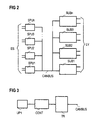
- Functional units SUB, SPU of a printing and copying machine there are eight Functional units SUB, SPU of a printing and copying machine shown. All functional units SPU, SUB are through a uniform CANBUS bus system for communication with each other coupled.
- a first group of functional units form the submodules SUB1..SUBn. With these submodules SUB1..SUBn is, for example, the controller the paper transport, the character generator and the fuser, as well as the central control of the printing or copying machine.
- These submodules SUB1..SUBn control the assigned ones Units, such as motors, heating devices and others Power consumers assigned to LV based on these aggregates Sensor elements.
- With the other functional units are simple sensor assemblies that are outside of the submodules SUB1..SUBn buttons, switches, display elements, Control temperature sensors, motors and sensors.
- the coupling of these sensor modules SPU1..SPUn to the bus system CANBUS takes place through an interface according to the figure 3.
- the SPU1..SPUn sensor module has a first one Microprocessor UP1, for example of the type 80C535, which the controls the functional elements assigned to the sensor module and monitors and reports that occur to a subordinate Controller CONT, for example of the 82C200 type or receives.
- This CONT controller leaves only those Messages and data from the CANBUS bus system pass through for the functionality of the SPU1..SPUn required are.
- the number of these relevant data messages is extremely small, so that the CONT controller only via a transmit memory and two selectable receive memories disposes.
- the connection of the CONT controller to the CANBUS bus system takes place via an analog driver module, for example of the type 82C250. In this driver block TR the level is adjusted to the CANBUS bus system.
- a second microprocessor UP2 is used to control a submodule SUB1..SUBn.
- the second microprocessor UP2 the type 80C167 can be used.
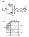
- This microprocessor UP2 communicates with the bus system via a DPRAM memory unit CANBUS.
- a third UP3 microprocessor for example the type 80C535. He communicates with a BCONT bus controller and this with a bus driver BTR.
- Type 80C200 can be used as a BCONT bus controller and as a bus driver BTR type 80C250 can be used.
- the second and the third microprocessor UP2, UP3 communicate immediately with the DPRAM memory unit.
- the storage unit is concerned it is a dual port RAM DPRAM.
- This dual-port RAM DPRAM is structured as shown in FIG. 5.
- the entire address range of the dual port RAM is DPRAM divided into two address areas AB1, AB2.
- everyone is there Address in the first address area AB1 an address in the second Address area AB2 assigned.
- the distance K between each other assigned addresses is always the same and is, for example 2 KB.
- Data is in the first address area AB1 and messages are filed and in the second address area AB2 Section data and news information 1 AB1 filed.
- the data and messages of the first address area AB1 are structured in blocks.
- a block D1, D2, Dn is replaced by a Designates the start address and is a maximum of 8 bytes long.
- Of the second section AB2 is also in blocks I1, I2, In structured.
- Each block I1, I2 ... In of the second address area AB2 contains information of the block assigned to it D1, D2, Dn of the first address area AB1.
- the distance K starting addresses of related blocks D1, I1, .. Dn, in which correspond to different sections AB1, AB2 the distance K of the related Addresses of the different address areas AB1, AB2.
- the information in the second address area AB2 relates to the associated data and message block.
- This information can be a label of what it is is new information that needs to be sent. It can also be information about how the Information from the DPRAM memory unit to the functional unit is to be reported. The information can be from the functional unit can be called up independently (RTR bit) or one Interrupt request makes the functional unit on the presence new information in the dual port RAM DPRAM.
- RTR bit Real-Time SR bit
- one Interrupt request makes the functional unit on the presence new information in the dual port RAM DPRAM.
- the length of the data of the associated data block in the first Address area AB1 is part of the information block I1..In. In general, it is information about how to process the data and messages D1..Dn further are.
- the receiving microprocessor UP2, UP3 through an interrupt routine on the data or messages D1..Dn should be pointed out, then the sender carries Processor UP2, UP3 the address of the first byte written a message in the first address area AB1 and the associated one Data length in a first-in-first-out (FIFO) register FIFO1, FIFO2 on.
- the FIFO register FIFO1, FIFO2 contains a FIFO empty line, those with the receiving processor UP2, UP3 is coupled and for each memory entry in the FIFO register FIFO1, FIFO2 an interrupt in the receiving microprocessor UP2, UP3 triggers.
- Each FIFO register FIFO1, FIFO2 is for one direction of transmission responsible. So the first FIFO register FIFO1 from third microprocessor UP3 and described by the second microprocessor UP2 read. The second FIFO register FIFO2 is described by the second microprocessor UP2 and by the third Microprocessor UP3 read.
- the FIFO registers FIFO1, FIFO2 can accommodate 128 different messages that generate an interrupt should trigger. These messages can be processed successively without changing their order.
- the immediate stopping of data or messages D1..Dn is favored in that the second microprocessor UP2 if there is a new message, an entry in the second FIFO register makes FIFO2. This is done regardless of the Information in the second address area AB2 of the dual-port RAM DPRAM.
- the third microprocessor UP3 is thus the data or message at the next opportunity via the bus system Transfer CANBUS to the other functional units SPU, SUB.
- each functional unit SUB1..SUBn, SPU1..SPUn always a current image of all sensors, consumers and control states of the printing or copying machine to disposal.
- the assignment of data or messages D1..Dn is particularly simple because in every dual-port RAM DPRAM this data or messages D1..Dn the same Address is assigned. For example, data or Messages D1..Dn to sensor 1 at start address 100 of a DPRAM. After transmission, these are available Data or messages D1..Dn in all dual port RAM's DPRAM the other functional units SUB1..SUBn are quasi-synchronous to disposal. You just have to start with address 100 to be read.
- a bus system CANBUS for the communication tasks described above can be used is from CAN bus specification 2.0, part A and B from April 94, known by Philips.
Landscapes
- Physics & Mathematics (AREA)
- General Physics & Mathematics (AREA)
- Engineering & Computer Science (AREA)
- Microelectronics & Electronic Packaging (AREA)
- Control Or Security For Electrophotography (AREA)
- Multi Processors (AREA)
- Image Input (AREA)
- Facsimiles In General (AREA)
Abstract
Description
- Figur 1
- eine Kommunikationseinrichtung gemäß dem Stand der Technik,
- Figur 2
- eine erfindungsgemäße Kommunikationseinrichtung in Blockdarstellung von Funktionsmodulen, die durch ein Bussystem miteinander gekoppelt sind,
- Figur 3
- eine vereinfachte Schnittstellenanordnung in Blockdarstellung mit Nachrichtenfilter,
- Figur 4
- eine Schnittstellenanordnung in Blockdarstellung mit Dualport-RAM und FIFO-Registern und
- Figur 5
- ein in zwei Speicherbereiche gegliedertes Dualport-RAM in schematischer Darstellung.
Claims (9)
- Kommunikationseinrichtung in einem elektrografischen Druck- und Kopiergerät mit einer Mehrzahl von Funktionseinheiten, die zur Datenkommunikation miteinander gekoppelt sind, miteiner Kopplung der Funktionseinheiten mittels eines einheitlichen Bussystems (CANBUS),einer jeder Funktionseinheit zugeordneten Schnittstelle zum Bussystem (CANBUS), die eine Speichereinheit (DPRAM) mit wahlfreiem Zugriff enthält, in der in definierten Adressbereichen (D1..Dn, I1..In) jeweils bestimmte Informationen zu den Funktionseinheiten ablegbar sind und durch das Bussystem (CANBUS) diese Informationen in sämtlichen Schnittstellen laufend aktualisiert werden, so daß jede Funktionseinheit zu jeder Zeit über ein Gesamtbild der Funktionszustände im elektrografischen Druck- und Kopiergerät verfügt.
- Kommunikationseinrichtung nach Anspruch 1 mit einem nachrichtenorientierten Bussystem (CANBUS), das eine Änderung einer Information unverzüglich an alle Funktionseinheiten übermittelt.
- Kommunikationseinrichtung nach einem der Ansprüche 1 oder 2, mit einem als sogenanntes Dual-Port-RAM ausgestalteten Speichereinheit (DPRAM) in jeder Funktionseinheit, dessen Adressbereich in zwei Einzelbereiche (AB1, AB2) aufgeteilt ist, wobei der erste Adressbereich (AB1) der Aufnahme von Daten und Nachrichten dient und der zweite Adressbereich (AB2) der Aufnahme von Informationen bezüglich der im ersten Adressbereich (AB1) hinterlegten Daten und Nachrichten dient.
- Kommunikationseinrichtung nach Anspruch 3, mit einer Zuordnung jeweils eines Daten- oder Nachrichtenblocks (D1..Dn) zu einem Informationsblock (I1..In) , so daß die Adressen der jeweils ersten Bytes der Blöcke einen bestimmten Adressabstand (K) zueinander haben.
- Kommunikationseinrichtung nach einem der Ansprüche 1 bis 4, mit zwei der Schnittstelle zugeordneten First-In-First-Out (FIFO) Registern, von denen eines busseitig beschreibbar und funktionseinheitsseitig lesbar und das andere in umgekehrter Richtung beschreib- und lesbar ist, in diese FIFO's die Adresse eines Daten- oder Nachrichtenblocks (D1..Dn) und dessen Länge in der Speichereinheit (DPRAM) mit wahlfreiem Zugriff eintragbar sind und das Auslesen dieser Information eine Unterbrechungsroutine im lesenden Prozessor (UP2, UP3) startet.
- Kommunikationseinrichtung nach einem der Ansprüche 1 bis 5, mit einer weiteren Schnittstelle zum Bussystem (CANBUS), die zur Ankopplung von Funktionseinheiten mit geringen Steuerungsaufgaben an das Bussystem (CANBUS) einsetzbar sind, wobei die weitere Schnittstelle so ausgestaltet ist, daß sie nur für die jeweilige Funktionseinheit bestimmte Daten und Nachrichten passieren läßt.
- Verfahren zur Kommunikation in einem elektrografischen Druck- und Kopiergerät zwischen einer Mehrzahl von Funktionseinheiten, die zur Datenkommunikation miteinander durch ein einheitliches Bussystem (CANBUS) gekoppelt sind, mit folgenden Verfahrensschritten:bei einer Initialisierung werden Schnittstellen zum Bussystem (CANBUS), die jeder Funktionseinheit zugeordnet sind in einen Grundzustand versetzt, so daß in einer Speichereinheit (DPRAM) mit wahlfreiem Zugriff, die in jeder Schnittstelle enthalten ist, die Grundzustandsdaten aller Funktionseinheiten in jeweils dafür definierten Adressbereichen (D1..Dn) verfügbar sind,beim Auftreten einer Änderung eines Zustandes einer Funktionseinheit wird diese Änderung in den betroffenen Adressbereich (D1..Dn) der Speichereinheit (DPRAM) eingetragen, die der Funktionseinheit zugeordnet ist, unddiese Änderung wird mittels des Bussystems (CANBUS) zu den Schnittstellen sämtlicher Funktionseinheiten übertragen und dort jeweils im betroffenen Adressbereich (D1..Dn) der Speichereinheit (DPRAM) abgelegt, so daß jede Funktionseinheit zu jeder Zeit über ein Gesamtbild der Funktionszustände im elektrografischen Druck- und Kopiergerät verfügt.
- Verfahren zur Kommunikation nach Anspruch 7, mit einer als sogenanntes Dual-Port-RAM ausgestalteten Speichereinheit (DPRAM) in jeder Funktionseinheit, dessen Adressbereich in zwei Einzelbereiche (AB1, AB2) aufgeteilt ist, wobei bei einer Änderung eines Zustandes einer Funktionseinheit in den ersten Adressbereich (AB1) Daten und Nachrichten und in den zweite Adressbereich (AB2) Informationen bezüglich der im ersten Adressbereich (AB1) hinterlegten Daten und Nachrichten eingetragen werden.
- Verfahren zur Kommunikation nach einem der Ansprüche 7 oder 8, mit zwei der Schnittstelle zugeordneten First-In-First-Out (FIFO) Registern, von denen eines busseitig beschreibbar und funktionseinheitsseitig lesbar und das andere in umgekehrter Richtung beschreib- und lesbar ist, wobei, abhängig von den in der Speichereinheit (DPRAM) bezüglich von zu ändernden Daten und Nachrichten hinterlegten Informationen, in den jeweils betroffenen FIFO die Adresse eines Daten- oder Nachrichtenblocks (D1..Dn) und dessen Länge eingetragen wird und das Auslesen dieser Information eine Unterbrechungsroutine im lesenden Prozessor (UP2, UP3) startet.
Applications Claiming Priority (3)
| Application Number | Priority Date | Filing Date | Title |
|---|---|---|---|
| DE19540672 | 1995-10-31 | ||
| DE19540672 | 1995-10-31 | ||
| PCT/DE1996/001463 WO1997016771A1 (de) | 1995-10-31 | 1996-08-05 | Kommunikationseinrichtung in einem elektrografischen druck- und kopiergerät |
Publications (2)
| Publication Number | Publication Date |
|---|---|
| EP0858621A1 EP0858621A1 (de) | 1998-08-19 |
| EP0858621B1 true EP0858621B1 (de) | 1999-03-17 |
Family
ID=7776338
Family Applications (1)
| Application Number | Title | Priority Date | Filing Date |
|---|---|---|---|
| EP96925648A Expired - Lifetime EP0858621B1 (de) | 1995-10-31 | 1996-08-05 | Kommunikationseinrichtung in einem elektrografischen druck- und kopiergerät |
Country Status (5)
| Country | Link |
|---|---|
| US (1) | US6122462A (de) |
| EP (1) | EP0858621B1 (de) |
| JP (1) | JP2000500880A (de) |
| DE (1) | DE59601474D1 (de) |
| WO (1) | WO1997016771A1 (de) |
Cited By (8)
| Publication number | Priority date | Publication date | Assignee | Title |
|---|---|---|---|---|
| US9125455B2 (en) | 2010-01-21 | 2015-09-08 | Boa Technology Inc. | Guides for lacing systems |
| USD751281S1 (en) | 2014-08-12 | 2016-03-15 | Boa Technology, Inc. | Footwear tightening reels |
| USD758061S1 (en) | 2014-09-08 | 2016-06-07 | Boa Technology, Inc. | Lace tightening device |
| US9375053B2 (en) | 2012-03-15 | 2016-06-28 | Boa Technology, Inc. | Tightening mechanisms and applications including the same |
| USD767269S1 (en) | 2014-08-26 | 2016-09-27 | Boa Technology Inc. | Footwear tightening reel |
| US9532626B2 (en) | 2013-04-01 | 2017-01-03 | Boa Technology, Inc. | Methods and devices for retrofitting footwear to include a reel based closure system |
| USD776421S1 (en) | 2015-01-16 | 2017-01-17 | Boa Technology, Inc. | In-footwear lace tightening reel |
| US10182935B2 (en) | 2014-10-01 | 2019-01-22 | Ossur Hf | Support for articles and methods for using the same |
Families Citing this family (10)
| Publication number | Priority date | Publication date | Assignee | Title |
|---|---|---|---|---|
| US20060156517A1 (en) | 1997-08-22 | 2006-07-20 | Hammerslag Gary R | Reel based closure system |
| DE19844859A1 (de) * | 1998-09-30 | 2000-04-20 | Eastman Kodak Co | Verfahren zum Steuern des Papierflusses durch ein Papierverarbeitungssystem |
| DE19850469A1 (de) * | 1998-11-02 | 2000-05-11 | Siemens Ag | Automatisierungssystem und Verfahren zum Zugriff auf die Funktionalität von Hardwarekomponenten |
| US6389262B1 (en) | 2001-04-06 | 2002-05-14 | Hewlett-Packard Company | Media reproduction systems and methods of operating media reproduction systems |
| WO2014124054A1 (en) | 2013-02-05 | 2014-08-14 | Boa Technology Inc. | Closure devices for medical devices and methods |
| US9629417B2 (en) | 2013-07-02 | 2017-04-25 | Boa Technology Inc. | Tension limiting mechanisms for closure devices and methods therefor |
| WO2015035257A2 (en) | 2013-09-05 | 2015-03-12 | Boa Technology Inc. | Alternative lacing guides for tightening mechanisms and methods therefor |
| KR102350912B1 (ko) | 2013-09-13 | 2022-01-13 | 보아 테크놀러지, 인크. | 릴 기반 폐쇄 장치 및 그에 따른 방법 |
| KR101895140B1 (ko) | 2013-11-18 | 2018-09-04 | 보아 테크놀러지, 인크. | 보철 및 장구의 자동 폐쇄를 제공하기 위한 방법 및 장치 |
| USD835898S1 (en) | 2015-01-16 | 2018-12-18 | Boa Technology Inc. | Footwear lace tightening reel stabilizer |
Family Cites Families (10)
| Publication number | Priority date | Publication date | Assignee | Title |
|---|---|---|---|---|
| US4062061A (en) * | 1976-04-15 | 1977-12-06 | Xerox Corporation | Error log for electrostatographic machines |
| US4306803A (en) * | 1977-08-30 | 1981-12-22 | Xerox Corporation | Microprocessor and control apparatus in a photocopier |
| US4523299A (en) * | 1982-09-21 | 1985-06-11 | Xerox Corporation | Message transmitting system for reproduction machines and copiers |
| US4811052A (en) * | 1985-08-08 | 1989-03-07 | Canon Kabushiki Kaisha | Control device for control of multi-function control units in an image processing apparatus |
| US5164769A (en) * | 1988-06-24 | 1992-11-17 | Ricoh Company, Ltd. | Method and apparatus for controlling data communication in a copying system |
| JP2734533B2 (ja) * | 1988-07-12 | 1998-03-30 | ミノルタ株式会社 | 画像形成装置 |
| US5087940A (en) * | 1990-08-23 | 1992-02-11 | Eastman Kodak Company | Control system for document reproduction machines |
| US5283613A (en) * | 1993-02-19 | 1994-02-01 | Xerox Corporation | Monitoring system with dual memory for electrophotographic printing machines using replaceable cartridges |
| US5471313A (en) * | 1993-02-24 | 1995-11-28 | Xerox Corporation | Method and control system architecture for controlling tone reproduction in a printing device |
| JP3559661B2 (ja) * | 1996-10-22 | 2004-09-02 | キヤノン株式会社 | 画像形成装置及び制御装置 |
-
1996
- 1996-08-05 WO PCT/DE1996/001463 patent/WO1997016771A1/de not_active Ceased
- 1996-08-05 JP JP9516969A patent/JP2000500880A/ja active Pending
- 1996-08-05 US US09/066,417 patent/US6122462A/en not_active Expired - Lifetime
- 1996-08-05 DE DE59601474T patent/DE59601474D1/de not_active Expired - Lifetime
- 1996-08-05 EP EP96925648A patent/EP0858621B1/de not_active Expired - Lifetime
Cited By (10)
| Publication number | Priority date | Publication date | Assignee | Title |
|---|---|---|---|---|
| US9125455B2 (en) | 2010-01-21 | 2015-09-08 | Boa Technology Inc. | Guides for lacing systems |
| US9375053B2 (en) | 2012-03-15 | 2016-06-28 | Boa Technology, Inc. | Tightening mechanisms and applications including the same |
| US9532626B2 (en) | 2013-04-01 | 2017-01-03 | Boa Technology, Inc. | Methods and devices for retrofitting footwear to include a reel based closure system |
| USD751281S1 (en) | 2014-08-12 | 2016-03-15 | Boa Technology, Inc. | Footwear tightening reels |
| USD767269S1 (en) | 2014-08-26 | 2016-09-27 | Boa Technology Inc. | Footwear tightening reel |
| USD758061S1 (en) | 2014-09-08 | 2016-06-07 | Boa Technology, Inc. | Lace tightening device |
| US10182935B2 (en) | 2014-10-01 | 2019-01-22 | Ossur Hf | Support for articles and methods for using the same |
| US11304838B2 (en) | 2014-10-01 | 2022-04-19 | Ossur Hf | Support for articles and methods for using the same |
| US12251327B2 (en) | 2014-10-01 | 2025-03-18 | Ossur Hr | Support for articles and methods for using the same |
| USD776421S1 (en) | 2015-01-16 | 2017-01-17 | Boa Technology, Inc. | In-footwear lace tightening reel |
Also Published As
| Publication number | Publication date |
|---|---|
| JP2000500880A (ja) | 2000-01-25 |
| DE59601474D1 (de) | 1999-04-22 |
| US6122462A (en) | 2000-09-19 |
| WO1997016771A1 (de) | 1997-05-09 |
| EP0858621A1 (de) | 1998-08-19 |
Similar Documents
| Publication | Publication Date | Title |
|---|---|---|
| EP1456722B1 (de) | Datenübertragungsverfahren, serielles bussystem und anschalteinheit für einen passiven busteilnehmer | |
| DE3689226T2 (de) | Multiprozessorsystem mit multihierarchischen Ebenen. | |
| DE2162806C2 (de) | Speichersteuereinheit zur vereinfachter Pufferung von Anforderungen der Ein- Ausgabekanäle | |
| DE69916937T2 (de) | Eingang-ausgangsuntersystem eines steuersystems | |
| DE3204905C2 (de) | ||
| DE3146356C2 (de) | Vorrichtung zur Steuerung der Übertragung von Gerätesteuerinformation in einem Datenendgerät | |
| WO1997016771A1 (de) | Kommunikationseinrichtung in einem elektrografischen druck- und kopiergerät | |
| EP1368935B1 (de) | Synchrones, getaktetes kommunikationssystem mit dezentralen ein-/ausgabe-baugruppen und verfahren zur einbindung dezentraler ein-/ausgabe-baugruppen in ein solches system | |
| DE3004827C2 (de) | Datenverarbeitungsanlage | |
| DE3238532C3 (de) | Datenübertragungseinrichtung | |
| DE69921446T2 (de) | Übertragungsstruktur für industrielle prozesssteuerungssysteme | |
| EP1361517A2 (de) | Datenverarbeitungsverfahren und Vorrichtung hierfür | |
| DE4340048A1 (de) | Vorrichtung zum Austauschen von Daten und Verfahren zum Betreiben der Vorrichtung | |
| EP1168120B1 (de) | Verfahren und Vorrichtung zur seriellen Datenübertragung zwischen einem Positionsmesssystem und einer Verarbeitungseinheit | |
| WO2003096637A2 (de) | Verfahren und system zur übertragung von daten über schaltbare datennetze | |
| DE69122142T2 (de) | Steuerungsanlage für ein Mehrprozessorsystem | |
| EP1095320B1 (de) | Steuerungssystem mit einem personalcomputer | |
| DE19744071B4 (de) | Eine programmierbare Logiksteuervorrichtung verwendendes Steuerungssystem | |
| DE60025969T2 (de) | Kraftfahrzeug-Steuerungssystem and Verfahren geeignet zur Revision der Steuerldatenübertragungsfunktion | |
| EP0739509B1 (de) | Anordnung mit master- und slave-einheiten | |
| DE69031673T2 (de) | Schnittstelle zur Verbindung von einem Rechnerbus mit einem faseroptischen Ringnetzwerk | |
| DE2751307C2 (de) | Einrichtung zur Steuerung einer IS-Glasformmaschine | |
| DE112008002252B4 (de) | Sendevorrichtung, Sendeverfahren und Kommunikationssystem | |
| DE69021626T2 (de) | Eingebettete Steuertechnik für verteilte Steuersysteme. | |
| DE69032078T2 (de) | Elektronische Anordnung mit Datenübertragungsfunktion |
Legal Events
| Date | Code | Title | Description |
|---|---|---|---|
| PUAI | Public reference made under article 153(3) epc to a published international application that has entered the european phase |
Free format text: ORIGINAL CODE: 0009012 |
|
| 17P | Request for examination filed |
Effective date: 19980312 |
|
| AK | Designated contracting states |
Kind code of ref document: A1 Designated state(s): BE DE FR GB |
|
| GRAG | Despatch of communication of intention to grant |
Free format text: ORIGINAL CODE: EPIDOS AGRA |
|
| GRAG | Despatch of communication of intention to grant |
Free format text: ORIGINAL CODE: EPIDOS AGRA |
|
| GRAH | Despatch of communication of intention to grant a patent |
Free format text: ORIGINAL CODE: EPIDOS IGRA |
|
| 17Q | First examination report despatched |
Effective date: 19980831 |
|
| GRAH | Despatch of communication of intention to grant a patent |
Free format text: ORIGINAL CODE: EPIDOS IGRA |
|
| GRAA | (expected) grant |
Free format text: ORIGINAL CODE: 0009210 |
|
| AK | Designated contracting states |
Kind code of ref document: B1 Designated state(s): BE DE FR GB |
|
| REF | Corresponds to: |
Ref document number: 59601474 Country of ref document: DE Date of ref document: 19990422 |
|
| ET | Fr: translation filed | ||
| GBT | Gb: translation of ep patent filed (gb section 77(6)(a)/1977) |
Effective date: 19990520 |
|
| PLBE | No opposition filed within time limit |
Free format text: ORIGINAL CODE: 0009261 |
|
| STAA | Information on the status of an ep patent application or granted ep patent |
Free format text: STATUS: NO OPPOSITION FILED WITHIN TIME LIMIT |
|
| 26N | No opposition filed | ||
| REG | Reference to a national code |
Ref country code: GB Ref legal event code: IF02 |
|
| PGFP | Annual fee paid to national office [announced via postgrant information from national office to epo] |
Ref country code: GB Payment date: 20070830 Year of fee payment: 12 |
|
| PGFP | Annual fee paid to national office [announced via postgrant information from national office to epo] |
Ref country code: BE Payment date: 20070823 Year of fee payment: 12 |
|
| PGFP | Annual fee paid to national office [announced via postgrant information from national office to epo] |
Ref country code: FR Payment date: 20070821 Year of fee payment: 12 |
|
| GBPC | Gb: european patent ceased through non-payment of renewal fee |
Effective date: 20080805 |
|
| REG | Reference to a national code |
Ref country code: FR Ref legal event code: ST Effective date: 20090430 |
|
| PG25 | Lapsed in a contracting state [announced via postgrant information from national office to epo] |
Ref country code: BE Free format text: LAPSE BECAUSE OF NON-PAYMENT OF DUE FEES Effective date: 20080831 |
|
| PG25 | Lapsed in a contracting state [announced via postgrant information from national office to epo] |
Ref country code: FR Free format text: LAPSE BECAUSE OF NON-PAYMENT OF DUE FEES Effective date: 20080901 |
|
| PG25 | Lapsed in a contracting state [announced via postgrant information from national office to epo] |
Ref country code: GB Free format text: LAPSE BECAUSE OF NON-PAYMENT OF DUE FEES Effective date: 20080805 |
|
| PGFP | Annual fee paid to national office [announced via postgrant information from national office to epo] |
Ref country code: DE Payment date: 20101029 Year of fee payment: 15 |
|
| PG25 | Lapsed in a contracting state [announced via postgrant information from national office to epo] |
Ref country code: DE Free format text: LAPSE BECAUSE OF NON-PAYMENT OF DUE FEES Effective date: 20130301 |
|
| REG | Reference to a national code |
Ref country code: DE Ref legal event code: R119 Ref document number: 59601474 Country of ref document: DE Effective date: 20130301 |