EP0857918A1 - Backofentür - Google Patents
Backofentür Download PDFInfo
- Publication number
- EP0857918A1 EP0857918A1 EP98102197A EP98102197A EP0857918A1 EP 0857918 A1 EP0857918 A1 EP 0857918A1 EP 98102197 A EP98102197 A EP 98102197A EP 98102197 A EP98102197 A EP 98102197A EP 0857918 A1 EP0857918 A1 EP 0857918A1
- Authority
- EP
- European Patent Office
- Prior art keywords
- frame
- profile part
- oven
- oven door
- frame profile
- Prior art date
- Legal status (The legal status is an assumption and is not a legal conclusion. Google has not performed a legal analysis and makes no representation as to the accuracy of the status listed.)
- Granted
Links
- 238000003801 milling Methods 0.000 claims abstract description 3
- 238000007493 shaping process Methods 0.000 claims abstract description 3
- 238000009423 ventilation Methods 0.000 claims description 43
- 238000001816 cooling Methods 0.000 claims description 24
- 229910052782 aluminium Inorganic materials 0.000 claims description 6
- XAGFODPZIPBFFR-UHFFFAOYSA-N aluminium Chemical compound [Al] XAGFODPZIPBFFR-UHFFFAOYSA-N 0.000 claims description 6
- 238000007688 edging Methods 0.000 claims description 6
- 229910052751 metal Inorganic materials 0.000 claims description 6
- 239000002184 metal Substances 0.000 claims description 6
- 125000006850 spacer group Chemical group 0.000 abstract description 13
- 239000000853 adhesive Substances 0.000 description 9
- 230000001070 adhesive effect Effects 0.000 description 9
- 238000013461 design Methods 0.000 description 9
- 238000004140 cleaning Methods 0.000 description 8
- 238000004519 manufacturing process Methods 0.000 description 6
- 239000000945 filler Substances 0.000 description 4
- 239000004033 plastic Substances 0.000 description 4
- 229920003023 plastic Polymers 0.000 description 4
- 229920001296 polysiloxane Polymers 0.000 description 4
- 238000000197 pyrolysis Methods 0.000 description 4
- 238000009413 insulation Methods 0.000 description 3
- 238000000034 method Methods 0.000 description 3
- 238000010276 construction Methods 0.000 description 2
- 238000004512 die casting Methods 0.000 description 2
- 239000003365 glass fiber Substances 0.000 description 2
- 239000000463 material Substances 0.000 description 2
- 239000002994 raw material Substances 0.000 description 2
- -1 Melt Substances 0.000 description 1
- 239000004696 Poly ether ether ketone Substances 0.000 description 1
- 230000006978 adaptation Effects 0.000 description 1
- JUPQTSLXMOCDHR-UHFFFAOYSA-N benzene-1,4-diol;bis(4-fluorophenyl)methanone Chemical compound OC1=CC=C(O)C=C1.C1=CC(F)=CC=C1C(=O)C1=CC=C(F)C=C1 JUPQTSLXMOCDHR-UHFFFAOYSA-N 0.000 description 1
- 239000005388 borosilicate glass Substances 0.000 description 1
- 230000003197 catalytic effect Effects 0.000 description 1
- 239000003795 chemical substances by application Substances 0.000 description 1
- 239000011248 coating agent Substances 0.000 description 1
- 238000000576 coating method Methods 0.000 description 1
- 239000002131 composite material Substances 0.000 description 1
- 150000001875 compounds Chemical class 0.000 description 1
- 238000011161 development Methods 0.000 description 1
- 238000005516 engineering process Methods 0.000 description 1
- 239000005357 flat glass Substances 0.000 description 1
- 239000008187 granular material Substances 0.000 description 1
- 230000017525 heat dissipation Effects 0.000 description 1
- 238000001746 injection moulding Methods 0.000 description 1
- 238000009434 installation Methods 0.000 description 1
- 238000010422 painting Methods 0.000 description 1
- 229920002530 polyetherether ketone Polymers 0.000 description 1
- 238000012805 post-processing Methods 0.000 description 1
- 239000000843 powder Substances 0.000 description 1
- 238000010079 rubber tapping Methods 0.000 description 1
- 239000013464 silicone adhesive Substances 0.000 description 1
- 238000005245 sintering Methods 0.000 description 1
- 239000007787 solid Substances 0.000 description 1
- 238000007711 solidification Methods 0.000 description 1
- 230000008023 solidification Effects 0.000 description 1
- 239000011232 storage material Substances 0.000 description 1
- 238000012546 transfer Methods 0.000 description 1
Images


Classifications
-
- F—MECHANICAL ENGINEERING; LIGHTING; HEATING; WEAPONS; BLASTING
- F24—HEATING; RANGES; VENTILATING
- F24C—DOMESTIC STOVES OR RANGES ; DETAILS OF DOMESTIC STOVES OR RANGES, OF GENERAL APPLICATION
- F24C15/00—Details
- F24C15/02—Doors specially adapted for stoves or ranges
- F24C15/04—Doors specially adapted for stoves or ranges with transparent panels
Definitions
- the invention relates to an oven door for an oven with oven muffle, the oven door being a frame-like Carrier for enclosing at least one pane element has and the frame-like carrier one Frame bottom and side edging strips, one form a frame wall defining the door interior.
- the frame base forms one facing the oven muffle Inner wall of the frame-like carrier.
- Oven doors with an external, visible side Outer pane and mostly an additional oven muffle side Inner pane are in several embodiments known.
- the frame-like carrier for mounting the at least one pane is in known doors composed of several individual parts. These items comprise a frame floor as a load-bearing basic element, the, based on the one mounted on the oven finished door, usually a muffle on the oven side forms the frame-like inner wall of the oven door.
- the frame base is usually a filling plate Viewing and carrying frame, which can hold a Disc serves.
- the filler plate is usually essentially just. However, this is not absolutely necessary it can also be structured or profiled.
- the Filling plate is also called and is a door filler plate preferably enamelled.
- the frame wall surrounding a door interior form with a face side and the Hold at least one pane.
- a door interior is the one located within the frame-like carrier To understand space between the inner and the outer pane.
- the edging strips mostly consist of extruded aluminum profiles.
- the outer pane is preferably with the inside Fastening elements on the frame-like carrier attached to them to the respective design requirements to be able to adapt.
- the inner pane is through the side edging strips attached to the filler plate clamped. However, you can also in the frame-like carrier glued.
- EP 0151359 A1 is one of many individual parts manufactured oven door with two panes known. She has a frame, the two side, between the Disc-arranged, vertical struts and an upper one and has a lower cross strut. The lower and upper Cross brace hold the two washers against the side, vertical struts pressed.
- oven doors which are a frame profile part from formed, for example deep-drawn, Have sheet metal on which the frame wall and the frame base are integrally formed.
- Such frame profile parts have the disadvantage that they are very easy warp.
- the profile shape due to the forming manufacturing technology set narrow design limits. You also need to install the oven door additional fastening elements in the frame profile part be welded in. The manufacturing and assembly effort Such oven doors are therefore very large.
- the invention is therefore based on the task, to create an oven door that is comparatively few Has individual parts, inexpensive to manufacture and simple is to be assembled.
- the oven door should be appealing Enable design.
- the frame wall and the frame base is a one-piece Rahnmenprofilteil the form frame-like carrier and the frame profile part in is essentially made by master shaping or milling.
- the oven door according to the invention has a basic element the frame-like carrier is a one-piece frame profile part on which other elements of the door are attached or can be trained.
- the frame profile part according to the invention Through the frame profile part according to the invention the necessary with conventional doors is eliminated separate mounting of the edging strips. About that the cover strips can also be dispensed with will.
- master forms is the manufacture of a molded part an informal raw material (e.g. granules, Melt, powder, etc.) understood. This is the informal The raw material is brought into a special master mold (for example, poured, pressed) in which it goes through Solidification, sintering etc. changes into the solid state. The molded part formed in this way, here the frame profile part, is taken from the master mold
- the frame profile part Due to the manufacturing process, the frame profile part has largely the shape required for the oven door and high dimensional accuracy, reducing the number of post-processing steps is reduced. It is also possible technically advantageous and aesthetically desired Realize profile shapes on the frame profile, which at Oven doors not assembled or only from individual parts are possible with a great deal of effort. Furthermore, can the material thickness vary within the frame profile part and be adapted to the respective requirements. For this reason, among other things, the invention Oven door reduces the risk of warping. Likewise, more can be done without high additional effort Elements for the assembly of the oven door and their Installation on the oven in one piece on the frame profile part be designed to further increase the assembly effort to reduce. The advantages mentioned can also apply to a Oven door reached with a milled frame profile part will.
- the oven door according to the invention is due to the due to the one-piece frame profile part less Number of grooves and slots easier to clean. Due to the one-piece of the frame profile part and its Realization as a molded part, it is also possible to create corners and Round off edges to create an overall aesthetic impression improve or make it variable as well as safety in use to increase.
- the one-piece frame profile part has an upper, lower, left and right frame sections.
- the closed Condition of the oven door installed on the oven has one on the frame wall of the frame profile part trained face side to the outside, while the frame floor is an oven muffle-side, i.e. the oven facing inner wall of the frame-like carrier forms.
- the frame profile part a disc bearing means for a first Disc element on.
- the frame profile part a holding surface for a second disc element on.
- the holding surface is preferably on the Frame bottom of the frame profile part formed.
- the oven door can have a third disc element. Therefore it can be advantageous if the frame profile part at least a spacer extending into the door interior for a third placed on a support surface Has disc element.
- the contact surface can the at least one spacer can be formed.
- the at least one spacer can preferably be in one piece be molded onto the frame profile, for example as Spacer or as a protruding part, the following is referred to as a "support dome".
- the Contact surface preferably arranged such that the third Disc element between the first disc element and the second disc element.
- a disc element can, depending on its arrangement within the frame profile part and its execution can be designed differently: it can essentially only from a disc in the frame profile part is attached directly, be formed.
- a disc element essentially comprises a disc element a disc and an intermediate beam (hereinafter referred to as "intermediate plate"), which the disc frame-like surrounds. Also several spaced apart marginally connected disks can - if necessary connected with an intermediate plate - a disc element form.
- the discs can be in different ways be fastened in the oven door.
- a first version can be one or more slices, for example the disc of the second disc element, by means of a Adhesive in the frame profile part or in a corresponding Intermediate plate, which is fastened in the frame profile part will be glued in.
- the adhesive used should be relatively heat resistant. Silicone-based adhesive and temperature-resistant two-component adhesive can be suitable for this.
- the frame profile part has at least one opening for attaching a Disc element by means of a fastener.
- the frame profile part can also be a door locking element have that with a door locking device of Oven interacts.
- the door locking element can be realized as a closure recess, for example which has a locking projection provided on the oven side, e.g. a door locking bolt or locking bolt engages, to keep the oven door closed.
- Door locking element can be formed with a Interlocking device of the oven interacts.
- the Door locking element can, for example, as a slot-shaped Locking opening to be formed in the locking element provided on the oven side, for example a movable hook that engages around the oven door, especially during pyrolytic self-cleaning lock the oven so that it does not open can be.
- the frame profile part can be a door handle connection element, for example, have two mounting holes, around the door handle without any design effort on the door attach or integrate.
- a door handle can too be integrally formed on the frame profile part.
- a heat protection frame is arranged, which surrounds a fourth disc element.
- the heat protection frame has the task, especially when Pyrolysis to maintain the baking chamber temperature and the disc elements located further out from the heat protect.
- the heat protection frame is preferably made of enamelled sheet.
- the fourth disc element can be attached to the heat protection frame in different ways be fixed, for example glued or with the help a fastener held by clamping action will.
- the oven door according to the invention can consist in that the frame profile part has at least one ventilation opening has to in particular when operating the oven the visible first disc element and the Cool the frame wall.
- the least a ventilation opening can for example be perforated or be slit-shaped.
- the frame profile part preferably has several vents on that essentially parallel to a section or several sections the frame wall are arranged.
- Advantageously can use the ventilation openings for indoor ventilation the oven door to a ventilation system on the oven side be connected.
- a section of the frame wall in particular on the side where the door handle is located, preferably has at least the frame profile part one extending into the door interior and essentially extending parallel to the section of the frame wall Cooling fin on.
- the at least one cooling fin will through air used to ventilate the door interior in this flows in, cooled and thereby brings about an improved Cooling the relevant section of the frame wall.
- the cooling fin on the frame profile part preferably formed in one piece.
- the oven door according to the invention can both on one Pull-out trolley for a baking sheet as well as on a folding hinge or joint can be attached.
- the frame profile part formed at least one bearing recess, which is a bearing element, for example, a bearing bushing, so that the pocket oven door on the front of the oven can be pivotally attached, the axis of rotation in particular be oriented vertically or horizontally can.
- metal As an advantageous material for the frame profile part aluminum has proven to be a minor one Weight and high stability as well is inexpensive and easy to process.
- the metal frame profile part can preferably essentially be designed as a die casting. By means of the die casting process manufactured frame profile parts are inexpensive and can be made in many different shapes will.
- the frame profile part can consist essentially of Be made of plastic.
- the suitable plastics for this must be stable at relatively high temperatures be.
- a frame profile part can be made of plastic, for example Injection molding process in large numbers, inexpensive and produce in many different shapes.
- Heat protection frame forms a door inner pane
- the fourth slice of one if necessary existing heat protection frame preferably includes Borosilicate glass.
- Figures 1 to 11 show two different variants a first preferred embodiment of the invention Oven door.
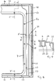
- Fig. 1 is a one-piece frame profile part 1 of Oven door with space for up to three Disc elements from its visible side without any Disc elements shown. Since the disc elements at this embodiment each consist of a disc, is used for the sake of simplicity in the description of "Slices” spoken instead of "slice elements". Of course, the disc elements can also be different be realized.
- An upper frame section 1a can be seen in the figure, a lower frame section 1b, a left frame section 1c and a right frame section 1d.
- the lateral frame sections 1c, 1d have openings 14 - in illustrated embodiment a total of four openings - For one fastener each for fastening a disc.
- Also on the right frame section 1d a formed as a locking recess Door closure element 19 to recognize.
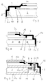
- Fig. 2 shows a section through the upper frame section 1a and the lower frame section 1b along the Line A-A '.
- the upper frame section 1a is described in more detail in FIG. 5.
- Fig. 3 is a section through the left frame section 1c and the right frame section 1d along the Line B-B 'can be seen.
- the left frame section 1c is shown in Fig. 6, the right frame portion 1d in Fig. 8 in more detail described.
- the upper left area of the frame profile part 1 is in Fig. 4 shown as a section.
- the disc bearing agent 6 is the first contact surface 6a and the holding surface 7 designed as a second contact surface 7a.
- a third contact surface 9 can be seen on the possibly existing third disc to lie can come, this washer an washer forms.
- Fig. 5 shows a section through the upper frame section 1a from Fig. 4 along the line A-A '.
- the frame wall 2 with molded-on frame base 4.
- An the visible end face 5 of the frame wall 2 is one first contact surface 6a for the outer pane of the oven door educated.
- the first contact surface 6a is one Recess or recess in the front side 5 of the Frame profile part 1 is formed. It only forms a partial area the end face 5, the support surface 6a, during the Rest of the end face 5 a lateral protrusion Protection of the disc forms.
- the second contact surface 7a is opposite to that oven muffle-side end of the frame profile part 1 in Set back towards the visible side of the oven door.
- the second contact surface is 7a inside the door from the inner pane, not shown arranged.
- spacer 8 On the frame profile part 1 is also in the door interior 3 extending spacer 8 with a third bearing surface 9 available.
- the spacer 8 is the spacer 8 as a one-piece, in the frame profile part 1 circumferential spacer educated.
- the spacer 8 can the support serve a possibly existing third disc, which in this case is an intermediate pane of the oven door forms that between the outer pane and the inner pane is arranged.
- FIG. 6 shows a section through the left frame section 1c from FIG. 4 along the line B-B '.
- the support surfaces 6a, 7a, 9 for the disks are also an opening 14 for a window fastener and a bearing recess 10 for receiving a bearing element to attach the oven door to the oven detect.
- Fig. 7 Cut an area on the left frame portion 1c outside the opening for a window fastener.
- a door lock member 19 in the form of a Locking recess or for fastening a locking bolt educated. Furthermore, are on the frame profile part 1 two door handle connection elements 20 for attachment of a door handle.
- FIG. 9 shows a section through the right frame section 1d with washers and fasteners
- Outer pane 11a is placed on first contact surface 6a, which is essentially a thickness the amount corresponding to the outer pane 11a is set back inward is.
- On the outer pane 11a is for the Attachment of the disc in the frame profile part 1 Holding element 16 attached, in the illustrated embodiment formed as a bracket 17 with a bore and glued to the disc with an adhesive is.
- the bracket works with a fastener 15 and the one formed on the frame profile part 1 Opening 14 together.
- the fastener 15 is as Realized screw with which the outer disc 11a on the Frame profile part 1 is screwed tight. However, it can other fasteners can be used, such as an elongated extension with a hook-shaped End that in an opening provided on the holding member 16 engages (snap lock).
- the inner pane 12a is from the outside on the second bearing surface 7a placed in and by means of an adhesive the frame profile part 1 glued.
- a third disc which forms an washer 13a and on the third bearing surface 9 rests.
- an elastic Element 18 for clamping the washer 13a arranged.
- the washer 13a is fixed when attaching (e.g. Screwing) the outer pane 11a in the frame profile part 1 clamped.
- To protect the outer pane 11a and Intermediate disk 13a can also be on the first contact surface 6a and the third bearing surface 9 each be arranged elastic element.
- FIG. 10 shows a section through a frame profile part 1 with inserted outer, inner and intermediate plate 11a, 12a, 13a in the area of the upper frame section 1c.
- the trained on the frame bottom 4 second contact surface 7a and that on the front side of the Frame wall 2 formed first support surface 6a around essentially the thickness of the inner pane 12a or Outer pane 11a corresponding amount, based on the Door interior 3, set back inside.
- the disks 12a, 11a only a little protrude beyond the frame profile part 1.
- FIG. 11 shows a variant of this embodiment of a Frame profile part 1 for an oven door according to the invention.
- the second contact surface 7a differs here to the previous variant on the outside of the door from the shown inner pane arranged, i.e. the second Support surface 7a is located on the oven muffle side of the inner pane.
- the described arrangement of the door locking element 19, the at least one bearing recess 10 and the door handle connection element 20 depends crucially on the method of fastening and operating the oven door according to the invention off the oven (e.g. can be swung open to the side, can be opened to the front, attached to a pull-out trolley).
- the first exemplary embodiment was used as an example described an oven door according to the invention, the hinged on the side of the oven and hinged on the left is.
- Figures 12 to 20 show a second embodiment an oven door according to the invention.
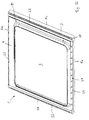
- Fig. 12 is the side facing the oven muffle of a one-piece frame profile part 1 of the oven door shown without disc elements.
- the frame profile part 1 has an upper frame portion 1a, a lower frame portion 1b and side frame sections 1c and 1d on.
- each frame section 1a, 1b, 1c, 1d arranged parallel to the frame wall 2. You are in that Frame profile part 1 all around, i.e. ring-shaped, formed.
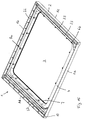
- Fig. 13 shows the one-piece frame profile part 1 of its visible side with inserted first disc element 11.
- Fig. 13b shows the ventilation slots 22 recognizable.
- the frame profile part 1 is without from its visible side used first disc element in Figures 14 and 15, the frame profile part 1 in FIG. 15 is rotated by 180 ° in comparison with that in FIG.
- the frame profile part 1 has one piece molded disk bearing means 6 for the first Disc element, the first disc of which is an outer disc forms on.
- the disk bearing means 6 are each realized as a projection with a hole that is below of the respective opening 14 extends into the door interior.
- Such disk bearing means 6 are in the following as Fastening domes 6b designated.
- the frame profile part 1 also has a holding surface 7 for a second disc element, the second disc forms an inner pane of the oven door. Furthermore is too recognize that the frame profile part 1 is in the door interior 3 extending spacing means 8 for a third Has disc element.
- the spacing means 8 are each as a one-piece projection with a bore realized and each have a bearing surface 9 for the third disc element.
- Such a trained one Spacer 8 is hereinafter referred to as the support dome 8a designated.
- the continuation of the ventilation slots 22 in the door interior 3 is in Fig. 14 for the upper frame portion 1a and the left frame portion 1c, in Fig. 15, for the lower one Frame section 1b and the right frame section 1d recognizable.
- the ventilation system is for example, the ventilation system for external cooling the oven muffle and for cooling the electronic components the oven. Flowing through the door interior 3 Cooling air cools the window elements and the frame wall 2, which reduces the risk that Users, for example when opening the oven door burn the outer pane 11a or the frame wall 2, or the adjacent furniture is damaged.
- cooling fins 23 For improved cooling of the frame wall 2 of the side Frame sections 1c, 1d are on their frame base 4, respectively two cooling fins 23 formed in one piece, which in each case essentially in these frame sections run parallel to the frame wall 2. Through the Ventilation slots 22 entering the door interior 3 Air flows past the cooling fins 23, causing the heat dissipation the frame wall 2 in the area of the side frame sections 1c and 1d is improved.
- the cooling fins 23 can also be designed or arranged differently. Further it may be sufficient just on the frame section, where the door handle is located, at least one cooling fin 23 to be provided. In ovens where none are very high operating temperatures occur or at which others Precautions for heat protection are taken (e.g. Provision of a further pane element, insulation measures), can also do without a cooling fin entirely will.
- the ventilation slots 22 on the Frame profile part 1 are arranged all around. It can be sufficient on one or more frame sections only provide ventilation slots 22 in sections, for example, in order to direct air along the cooling fins 23. Furthermore, the opening cross section of the Vents 22 depending on the arrangement and function of the respective ventilation slots 22 (air inlet, air outlet) different within the frame profile part 1 be great. Overall, the air flow depends on the Door interior 3 from numerous influencing factors, in particular on the type of ventilation system to which the door interior 3 is connected, the number, the dimensions and the arrangement of the ventilation slots 22, the volume of the door interior 3, etc. These influencing factors are known to the expert. He can do it in a common way and Vary the way to get the required air flow (by means of Convection or forced ventilation) through the door interior 3 to realize.
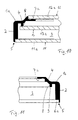
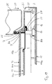
- FIG. 16 shows a section from the right area of the frame profile part 1.
- the right frame section 1d is with adjacent upper frame section 1a as well adjacent lower frame section 1b shown.
- the ventilation slots 22nd are different within the frame profile part 1.
- the ventilation slots in particular 22 on the upper frame portion 1a large cross section, since this frame section when closed Oven door on the pressure side of the fan the oven ventilation system is arranged (see Fig. 19).
- Through the narrower ventilation slots 22 on the right frame section 1d can by in the door interior 3 flowing cooling air secondary air can be sucked in.
- the air occurs essentially through the vents 22 of the lower frame section 1b from the door interior 3.
- the flow path of the cooling air depends on Door interior 3 depends on which side of the oven the pressure side of the ventilation system fan is located, to which the door interior 3 is connected. Consequently, other ventilation slots 22 in the essential to the air inlet or outlet to serve.
- FIG. 17 shows a partial section through the right frame section 1d from Fig. 16.
- the frame wall 2 is in one piece molded onto the frame base 4.
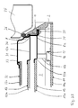
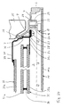
- FIG. 18 shows a section through the right frame section 1d from FIG. 16 with disk elements and disk element fastening means.
- a section of the components is an oven muffle 25 indicated. It can be seen that the frame wall 2 with adjacent frame base 4, the cooling fins 23, the Holding surface 7, the support dome 8a and the mounting dome 6b are integrally formed on the frame profile part 1.
- the holding surface 7 is on the outside of the door from the second Disc element 12, which in this embodiment the second disc 12a is arranged.
- This arrangement the holding surface 7 has the advantage that the assembly the disc elements with the exception of the disc element, that includes the front window of the oven door, from one Direction can take place. This reduces the number the one required to assemble the oven door Handling steps and the risk that the enamelling, Coating or painting the frame profile part 1 at assembly is damaged.
- a door seal 26, for example made of silicone to seal the oven door against the oven muffle 25 is between the second disc 12a and the holding surface 7 held by clamping action.
- the third disc element 13, the third disc 13a forms an intermediate plate of the oven door, includes next the third disc 13a a molded first intermediate plate 13b, which surrounds the intermediate plate 13a like a frame.
- the third washer 13a is in a recess of the first intermediate plate 13b glued. Alternatively could also use fasteners be pinched.
- the first intermediate plate 13b lies on the contact surfaces 9 of the support dome 8a and is with the help of a fastener attached to them.
- a fastener screws are used for the third disk element 13 27, preferably self-tapping screws, the Shaft through a hole in the first intermediate plate 13b extends and into the support domes 8a are screwed in.
- the screws 27 are preferably also used for Attachment of the second disc element 12.
- To this Purpose are holding brackets 28 provided with a bore provided through openings in the first intermediate plate Reach through 13b.
- To attach the second and third disc elements 12 and 13 are the brackets 28 and the first intermediate plate 13b by means of the screws 27 screwed onto the support domes 8a, each the shaft of a screw 27 through a hole in the Bracket 28 and through a hole in the first intermediate plate 13b engages.
- One end of the Bracket 28 against the edge of the second disc 12a the door seal 26 and this against the holding surface 7.
- each has a bracket 26 with a fastener and one on the frame profile part 1 trained opening 14, which Fasteners advantageously also here Screw is realized.
- One screw is from the side of the frame profile part facing the oven muffle 1 inserted into an opening 14. It extends it through the bore of the mounting dome 6b and is screwed into the bracket 17.
- Im used and screwed state is the first Disk 11a preferably does not open in its edge region the frame wall 2, but is on the bracket 17th supported on the mounting domes 6b.
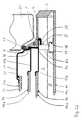
- FIG. 19 shows a section through the upper frame section 1a with inserted disc elements 11, 12, 13 and disk element fasteners the oven door on the oven arranged such that the ventilation slots 22 on the indicated by an arrow 29 Pressure side of a fan of a ventilation system are arranged. Cooling air passes through the ventilation slot 22, whose flow path is illustrated by an arrow 30 is in the door interior 3. With this cut is the hole in the support dome 8a, in which the Screw 27 is screwed in, can be seen.
- the minimum frame thickness for a frame profile part made of die-cast aluminum is preferably at least 0.5 mm, preferably at least 1.0 mm.
- Typical wall thicknesses for cast aluminum are 1.5 mm to 3 mm; larger wall thicknesses up to 10 mm and more are possible.
- Oven doors essentially for ovens without pyrolytic self-cleaning are suitable.
- Such Doors are for ovens with pyrolytic self-cleaning less preferred because temperatures up to during pyrolysis occur at 500 ° C, at which the frame profile part and the disc elements of the previously described embodiments can heat up too much.
- FIGS A third preferred embodiment is shown in FIGS described the oven door according to the invention, for an oven with pyrolytic self-cleaning suitable is.
- the cut positions correspond to Figures the cut positions shown in Fig. 16 for the second embodiment. 21 thus shows one Section through the right frame section 1d, FIG. 22 a section through the upper frame portion 1a ( however no ventilation slot 22 is cut) and Fig. 23 shows a section through the lower frame section 1b.
- a heat protection frame 31 In contrast to the construction of the oven door according to the second embodiment is on the frame profile part 1 Oven-side a heat protection frame 31 with a fourth disk element 32 in the form of a fourth disk 32a arranged.
- the fourth disc 32a is on the heat protection frame 31, which is made of enamelled sheet metal, preferably clamped by means of holding elements. she however, could also be glued or otherwise attached be. Between the fourth disc 32a and the heat protection frame 31 there is a glass fiber seal 33.
- the second disc element comprises 12 a second disc 12a and a frame-like one second intermediate plate 12b with a circumferential recess, into which the second disc 12a is inserted and there is stuck.
- the heat protection frame 31 is in the Frame profile part 1 held by clamping action by its edge 36 between the door seal 26 and the edge of the second intermediate plate 12b is arranged.
- the ends of the Bracket 28 thus hold the second intermediate plate 12b, the edge 36 of the heat protection frame 31 and the door seal 26 pressed against the holding surface 7. Otherwise corresponds the structure of the oven door that of Figures 12 to 20.
- other options are possible, around the heat protection frame 31 and the second pane element 12 to be fixed in the frame profile part 1.
- An advantageous variant can, for example, be in it exist that the second disc 12a and the third Disc 13a, or the second disc element 12 and that third disc element 13 represent a composite structure and be attached together. 24 is an embodiment explained.
- FIG. 24 shows a section through the left frame section 1d on a section corresponding to section B-B 'from FIG. 16 Place of a fourth embodiment of the invention, namely an oven door with a heat protection frame.
- This embodiment differs from the third Embodiment essentially through the structure and Assembly of the between the further disc element 32 of the Heat protection frame 31 and the first pane element 11 arranged washers.
- Form the washers here another disc element 35 in the form of a Disc packs with two arranged parallel to each other Disks 35a, 35b. They are around the edge with help an adhesive 34 made of a temperature-resistant adhesive (e.g. silicone adhesive) bonded together, with the help of a spacer, not shown kept apart from each other.
- a temperature-resistant adhesive e.g. silicone adhesive
- the Discs 35a, 35b of the further disc element 35 correspond thus the second disc 12a and the third Disk 13a in that shown in Figures 21 to 23 Embodiment.
- the disc package is on a frame-like another intermediate plate 35c of the further disk element 35 glued on. Of course it could too be clamped with the help of fasteners.
- the another intermediate plate 35c is the same as the first Intermediate plate 13b screwed to the support dome 8a, the bracket 28 in this embodiment Edge 36 of the heat protection frame 31 and the door seal 26 presses against the holding surface 7. Otherwise corresponds to Structure of the oven door that of FIGS. 21 to 23 described oven door.
- a disc element with a disc package could also be used an embodiment without a heat protection frame advantageous can be used to reduce the assembly effort.
- the number of disks 11a, 12a, 13a, 32a, 35a, 35b of the Disc elements 11, 12, 13, 32, 35 and their arrangement have within the frame profile part 1 among others Influence on the temperature at the first disc 11a first disc element 11, which forms an outer disc, and the temperature on the frame wall 2. This temperature should preferably be less than 80 ° C.
- the intervals are self-cleaning between the first disc 11a of the first disc element 11 and the third disc 13a of the third disc element 13 advantageously 0.3 cm to 2.5 cm and between the third disc 13a of the third disc element 13 and the second disc 12a of the second disc element 12 advantageously 0.2 cm to 2.0 cm.
- the distance between the fourth Washer 32a of the heat protection frame 31 and the second Disc 12a of the second disc element 12 advantageously 0.3 cm to 2.5 cm.
- the distances between the Discs of the other disc elements correspond to essentially the one above for an oven door without a heat protection frame distances mentioned. With an oven door with heat protection frame 31 and further pane element 35 with disc package, the distances mentioned in essentially accordingly.
Landscapes
- Engineering & Computer Science (AREA)
- Chemical & Material Sciences (AREA)
- Combustion & Propulsion (AREA)
- Mechanical Engineering (AREA)
- General Engineering & Computer Science (AREA)
- Electric Ovens (AREA)
- Baking, Grill, Roasting (AREA)
Abstract
Description
- Fig. 1
- eine sichtseitige Aufsicht auf ein einstückiges Rahmenprofilteil gemäß einer ersten bevorzugten Ausführungsform der Erfindung,
- Fig. 2
- einen Schnitt A-A' zu Fig. 1,
- Fig. 3
- einen Schnitt B-B' zu Fig. 1,
- Fig. 4
- einen Detailausschnitt aus dem oben links gelegenen Rahmenabschnitt von Fig. 1,
- Fig. 5
- einen Schnitt A-A' zu Fig. 4,
- Fig. 6
- einen Schnitt B-B' zu Fig. 4,
- Fig. 7
- einen ersten Detailschnitt aus dem linken Rahmenabschnitt des Rahmenprofilteiles von Fig. 1,
- Fig. 8
- einen zweiten Detailschnitt aus dem rechten Rahmenabschnitt des Rahmenprofilteiles von Fig. 1,
- Fig. 9
- einen dritten Detailschnitt aus dem rechten Rahmenabschnitt des Rahmenprofilteiles (mit Scheiben) von Fig. 1,
- Fig. 10
- einen vierten Detailschnitt aus dem oberen Rahmenabschnitt des Rahmenprofilteiles (mit Scheiben) von Fig. 1,
- Fig. 11
- einen fünften Detailschnitt aus dem unteren Rahmenabschnitt des Rahmenprofilteiles (ohne Scheiben) von Fig. 1,
- Fig. 12
- eine backofenmuffel-seitige perspektivische Aufsicht auf ein einstückiges Rahmenprofilteil gemäß einer zweiten bevorzugten Ausführungsform der Erfindung,
- Fig. 13
- eine sichtseitige perspektivische Aufsicht auf das Rahmenprofilteil von Fig. 12 mit eingesetztem ersten Scheibenelement,
- Fig. 14
- eine sichtseitige perspektivische Aufsicht auf das Rahmenprofilteil von Fig. 12,
- Fig. 15
- eine Fig. 14 entsprechende Darstellung aus einer anderen Blickrichtung,
- Fig. 16
- einen Detailausschnitt aus dem Rahmenprofilteil von Fig. 12,
- Fig. 17
- einen Schnitt A-A' zu Fig. 16,
- Fig. 18
- einen Schnitt B-B' zu Fig. 16,
- Fig. 19
- einen Schnitt C-C' zu Fig. 16,
- Fig. 20
- einen Schnitt D-D' zu Fig. 16,
- Fig. 21
- einen der Schnittlage B-B' aus Fig. 16 entsprechenden Schnitt durch ein Rahmenprofilteil gemäß einer dritten bevorzugten Ausführungsform der Erfindung,
- Fig. 22
- einen der Schnittlage C-C' aus Fig. 16 entsprechenden Schnitt durch das Rahmenprofilteil gemäß der dritten bevorzugten Ausführungsform der Erfindung,
- Fig. 23
- einen der Schnittlage D-D' aus Fig. 16 entsprechenden Schnitt durch das Rahmenprofilteil gemäß der dritten bevorzugten Ausführungsform der Erfindung und
- Fig. 24
- einen der Schnittlage B-B' aus Fig. 16 entsprechenden Schnitt durch ein Rahmenprofilteil gemäß einer vierten bevorzugten Ausführungsform der Erfindung.
- 1
- Rahmenprofilteil
- 1a
- oberer Rahmenabschnitt
- 1b
- unterer Rahmenabschnitt
- 1c
- linker Rahmenabschnitt
- 1d
- rechter Rahmenabschnitt
- 2
- Rahmenwand
- 3
- Türinnenraum
- 4
- Rahmenboden
- 5
- Stirnseite zu 1
- 6
- Scheibenlagermittel
- 6a
- erste Auflagefläche
- 6b
- Befestigungsdom
- 7
- Haltefläche
- 7a
- zweite Auflagefläche
- 8
- Abstandsmittel
- 8a
- Auflagedom
- 9
- (dritte) Auflagefläche
- 10
- Lageraussparung
- 11
- erstes Scheibenelement
- 11a
- erste Scheibe (Außenscheibe)
- 12
- zweites Scheibenelement
- 12a
- zweite Scheibe (Innenscheibe bzw. Zwischenscheibe)
- 12b
- zweites Zwischenblech
- 13
- drittes Scheibenelement
- 13a
- dritte Scheibe (Zwischenscheibe)
- 13b
- erstes Zwischenblech
- 14
- Öffnung
- 15
- Befestigungsmittel
- 16
- Halteelement
- 17
- Haltebügel
- 18
- elastisches Element
- 19
- Türverschlußelement
- 20
- Türgriffanschlußelement
- 21
- Lüftungsöffnung
- 22
- Lüftungsschlitz
- 23
- Kühlrippe
- 24
- Verriegelungsöffnung
- 25
- Backofenmuffel
- 26
- Türdichtung
- 27
- Schraube
- 28
- Haltewinkel
- 29
- Druckseite eines Lüftungssystems
- 30
- Strömungsweg der Kühlluft
- 31
- Hitzeschutzrahmen
- 32
- viertes Scheibenelement
- 32a
- vierte Scheibe
- 33
- Glasseidendichtung
- 34
- Verklebung
- 35
- weiteres Scheibenelement
- 35a
- Scheibe von 35
- 35b
- Scheibe von 35
- 35c
- weiteres Zwischenblech
- 36
- Rand von 31
Claims (18)
- Backofentür für einen Backofen mit Backofenmuffel (25), wobei die Backofentür einen rahmenartigen Träger zum Einfassen mindestens eines Scheibenelements aufweist und der rahmenartige Träger einen Rahmenboden (4) und seitliche Einfassungsleisten, die eine einen Türinnenraum (3) umgrenzende Rahmenwand (2) bilden, umfaßt, wobei der Rahmenboden (4) eine der Backofenmuffel (25) zugewandte Innenwand des rahmenartigen Trägers bildet,
dadurch gekennzeichnet, daß
die Rahmenwand (2) und der Rahmenboden (4) ein einstückiges Rahmenprofilteil (1) des rahmenartigen Trägers bilden und das Rahmenprofilteil (1) im wesentlichen durch Urformen oder Fräsen gefertigt ist. - Backofentür nach Anspruch 1, dadurch gekennzeichnet, daß das Rahmenprofilteil (1) ein Scheibenlagermittel (6, 6a, 6b) für ein erstes Scheibenelement (11) aufweist.
- Backofentür nach Anspruch 1 oder 2, dadurch gekennzeichnet, daß das Rahmenprofilteil (1) eine Haltefläche (7, 7a) für ein zweites Scheibenelement (12) aufweist.
- Backofentür nach Anspruch 3, dadurch gekennzeichnet, daß die Haltefläche (7, 7a) an dem Rahmenboden (4) des Rahmenprofilteiles (1) ausgebildet ist.
- Backofentür nach Anspruch 4, dadurch gekennzeichnet, daß die Haltefläche (7, 7a) türaußenseitig von dem zweiten Scheibenelement (12) angeordnet ist.
- Backofentür nach einem der vorhergehenden Ansprüche, dadurch gekennzeichnet, daß das Rahmenprofilteil (1) mindestens ein sich in den Türinnenraum (3) erstreckendes Abstandsmittel (8, 8a) für ein auf einer Auflagefläche (9) aufgelegtes drittes Scheibenelement (13) aufweist.
- Backofentür nach Anspruch 6, dadurch gekennzeichnet, daß das mindestens eine Abstandsmittel (8, 8a) einstückig an dem Rahmenprofilteil (1) angeformt ist.
- Backofentür nach Anspruch 6 oder 7, dadurch gekennzeichnet, daß das dritte Scheibenelement (13) zwischen dem ersten Scheibenelement (11) und dem zweiten Scheibenelement (12) angeordnet ist.
- Backofentür nach einem der vorhergehenden Ansprüche, dadurch gekennzeichnet, daß das Rahmenprofilteil (1) mindestens eine Öffnung (14) für ein Befestigungselement (15) zum Befestigen eines Scheibenelements (11, 12, 13) aufweist.
- Backofentür nach Anspruch 9, dadurch gekennzeichnet, daß an einem Scheibenelement (11,12,13), insbesondere an dem ersten Scheibenelement (11), ein Halteelement (16), vorzugsweise ein Haltebügel (17), befestigt ist, das mit dem Befestigungsmittel (15) und der mindestens einen Öffnung (14) zum Befestigen eines Scheibenelements (11,12,13) zusammenwirkt.
- Backofentür nach einem der vorhergehenden Ansprüche, dadurch gekennzeichnet, daß das Rahmenprofilteil (1) im wesentlichen aus Metall, insbesondere aus Aluminium, vorzugsweise im wesentlichen als Druckguß, gefertigt ist.
- Backofentür nach einem der vorhergehenden Ansprüche, dadurch gekennzeichnet, daß sie einen Hitzeschutzrahmen (31) aufweist, der backofenmuffel-seitig an dem Rahmenprofilteil (1) angeordnet ist, ein viertes Scheibenelement (32) einfaßt und vorzugsweise im wesentlichen aus emailliertem Blech gebildet ist.
- Backofentür nach einem der vorhergehenden Ansprüche, dadurch gekennzeichnet, daß das Rahmenprofilteil (1) mindestens eine Lageraussparung (10) für die Aufnahme eines Lagerelementes zum Befestigen der Backofentür an dem Backofen aufweist.
- Backofentür nach einem der vorhergehenden Ansprüche, dadurch gekennzeichnet, daß das Rahmenprofilteil (1) mindestens eine Lüftungsöffnung (21) für die Innenbelüftung des Türinnenraumes (3) aufweist.
- Backofentür nach Anspruch 14, dadurch gekennzeichnet, daß das Rahmenprofilteil (1) mehrere Lüftungsöffnungen (21) aufweist, die im wesentlichen parallel zu einem Abschnitt der Rahmenwand (2) oder zu mehreren Abschnitten der Rahmenwand (2) angeordnet sind.
- Backofentür nach einem der vorhergehenden Ansprüche, dadurch gekennzeichnet, daß das Rahmenprofilteil (1) mindestens eine sich in den Türinnenraum (3) erstreckende und im wesentlichen parallel zu einem Abschnitt der Rahmenwand (2) verlaufende Kühlrippe (23) aufweist.
- Backofentür nach Anspruch 16, dadurch gekennzeichnet, daß die Kühlrippe (23) an dem Rahmenprofilteil (1) einstückig angeformt ist.
- Backofen mit einer Backofentür, dadurch gekennzeichnet, daß die Backofentür nach einem der Ansprüche 1 bis 17 ausgebildet ist.
Applications Claiming Priority (2)
| Application Number | Priority Date | Filing Date | Title |
|---|---|---|---|
| DE19705120A DE19705120A1 (de) | 1997-02-11 | 1997-02-11 | Backofentür |
| DE19705120 | 1997-02-11 |
Publications (2)
| Publication Number | Publication Date |
|---|---|
| EP0857918A1 true EP0857918A1 (de) | 1998-08-12 |
| EP0857918B1 EP0857918B1 (de) | 2002-10-23 |
Family
ID=7819881
Family Applications (1)
| Application Number | Title | Priority Date | Filing Date |
|---|---|---|---|
| EP98102197A Expired - Lifetime EP0857918B1 (de) | 1997-02-11 | 1998-02-09 | Backofentür |
Country Status (3)
| Country | Link |
|---|---|
| EP (1) | EP0857918B1 (de) |
| DE (2) | DE19705120A1 (de) |
| ES (1) | ES2186028T3 (de) |
Cited By (10)
| Publication number | Priority date | Publication date | Assignee | Title |
|---|---|---|---|---|
| EP0997689A3 (de) * | 1998-10-29 | 2001-12-19 | BSH Bosch und Siemens Hausgeräte GmbH | Backofen mit Vollglasinnenscheibe |
| EP1178264A1 (de) * | 2000-08-03 | 2002-02-06 | AEG Hausgeräte GmbH | Tür für ein Haushaltsgerät, inbesondere einen Haushaltsgarofen |
| FR2857084A1 (fr) | 2003-07-02 | 2005-01-07 | Bsh Bosch Siemens Hausgeraete | Porte de four de cuisiniere, unite a vitre intermediaire et four |
| WO2005017413A1 (de) * | 2003-08-14 | 2005-02-24 | BSH Bosch und Siemens Hausgeräte GmbH | Backofentür und türboden dafür |
| EP2090832A1 (de) * | 2008-02-15 | 2009-08-19 | Electrolux Home Products Corporation N.V. | Türensystem zur Schließung einer Zufuhrvorrichtung zum Garraum eines Backofens |
| DE102008042467A1 (de) * | 2008-09-30 | 2010-04-01 | BSH Bosch und Siemens Hausgeräte GmbH | Ofentür für den Garraum eines Backofens vorzugsweise mit einer Einrichtung zur pyrolytischen Selbstreinigung |
| EP2602554A1 (de) * | 2011-12-09 | 2013-06-12 | BSH Bosch und Siemens Hausgeräte GmbH | Tür für ein Haushaltsgerät, Haushaltsgerät mit einer Tür und Verfahren zum Montieren eines Türprofils |
| EP2851622A1 (de) * | 2013-09-19 | 2015-03-25 | Electrolux Appliances Aktiebolag | Eine Haltestruktur für ein erstes folienartiges Element, Verfahren zur Montage derselben und Verfahren zur Herstellung derselben |
| WO2015180790A1 (en) * | 2014-05-30 | 2015-12-03 | Arcelik Anonim Sirketi | Glass door with improved safety against breakage for use in a household appliance and method of manufacturing the same |
| EP2340400B1 (de) * | 2008-10-31 | 2018-08-08 | Arçelik Anonim Sirketi | Ofen mit einer tür, deren temperatur in einem sicheren bereich gehalten wird |
Families Citing this family (17)
| Publication number | Priority date | Publication date | Assignee | Title |
|---|---|---|---|---|
| DE19734959C2 (de) * | 1997-08-13 | 2001-06-13 | Aeg Hausgeraete Gmbh | Ofenmuffeltür mit Wärmeisolationskörper zur Zwischenscheibenhalterung |
| DE19933251A1 (de) * | 1999-07-15 | 2001-01-25 | Aeg Hausgeraete Gmbh | Tür für ein Gerät, insbesondere einen Garofen |
| EP1076210B1 (de) | 1999-08-11 | 2013-06-26 | Electrolux Rothenburg GmbH Factory and Development | Tür für ein Gerät, insbesondere einen Garofen, mit elastischen Rückstellkörpern zum Halten der Scheiben |
| DE50006235D1 (de) | 1999-11-30 | 2004-06-03 | Aeg Hausgeraete Gmbh | Tür für einen Garofen mit Trägerelementen aus Kunststoff |
| DE10026468A1 (de) * | 2000-05-27 | 2001-12-06 | Bayer Isolierglas & Maschtech | Verschluß für Geräte mit hoher Innentemperatur |
| DE10039445C2 (de) * | 2000-08-11 | 2003-12-18 | Bsh Bosch Siemens Hausgeraete | Backofentür |
| DE10050609A1 (de) * | 2000-10-12 | 2002-04-18 | Bsh Bosch Siemens Hausgeraete | Gargerätetür |
| DE10061779A1 (de) | 2000-12-12 | 2002-06-20 | Aeg Hausgeraete Gmbh | Haltevorrichtung für mindestens eine Türscheibe, insbesondere für eine Türscheibe eines Garofens |
| DE10105543A1 (de) * | 2001-02-06 | 2002-08-08 | Bsh Bosch Siemens Hausgeraete | Gargerät mit Tür |
| DE10153618A1 (de) * | 2001-10-31 | 2003-06-18 | Bsh Bosch Siemens Hausgeraete | Backofentür |
| DE10208495A1 (de) * | 2002-02-27 | 2003-09-04 | Bsh Bosch Siemens Hausgeraete | Gargerät sowie Gargerätetür |
| DE10239180A1 (de) | 2002-08-21 | 2004-03-04 | BSH Bosch und Siemens Hausgeräte GmbH | Garraumtür eines Garofens mit Pyrolysefunktion |
| DE102005033225B4 (de) * | 2005-07-15 | 2021-09-30 | BSH Hausgeräte GmbH | Hausgerätetürelement und Backofentür mit einem solchen Hausgerätetürelement |
| DE102005044694A1 (de) * | 2005-09-19 | 2007-03-22 | BSH Bosch und Siemens Hausgeräte GmbH | Hocheinbau-Gargerät |
| DE102006001294A1 (de) * | 2006-01-10 | 2007-07-12 | BSH Bosch und Siemens Hausgeräte GmbH | Gargerätetür mit einer außenseitigen Scheibe |
| ES2381288B1 (es) * | 2012-02-21 | 2013-01-24 | Industrias Hergom S.A. | Puerta para aparatos calefactores con cámara de combustión de leña |
| ES2597862B1 (es) * | 2015-07-23 | 2017-10-31 | Calvet Brothers, S.L. | Puerta de horno con sellado mejorado |
Citations (4)
| Publication number | Priority date | Publication date | Assignee | Title |
|---|---|---|---|---|
| US3996710A (en) * | 1975-04-11 | 1976-12-14 | General Electric Company | Simplified oven door window |
| DE2545531B2 (de) * | 1975-10-10 | 1978-05-18 | Bosch-Siemens Hausgeraete Gmbh, 7000 Stuttgart | Backofentür mit einem Sichtfenster |
| US5441036A (en) * | 1994-08-29 | 1995-08-15 | Whirlpool Corporation | Cool multi-sectioned oven door for a large window oven |
| EP0731318A1 (de) * | 1995-03-06 | 1996-09-11 | Bosch-Siemens HausgerÀ¤te GmbH | Backofen |
Family Cites Families (4)
| Publication number | Priority date | Publication date | Assignee | Title |
|---|---|---|---|---|
| FR758131A (fr) * | 1933-07-07 | 1934-01-11 | United Gas Industries Ltd | Perfectionnements aux fourneaux de cuisine |
| FR2557272B1 (fr) * | 1983-12-22 | 1988-06-17 | Europ Equip Menager | Porte d'un appareil de cuisson |
| DE4333033C1 (de) * | 1993-09-29 | 1995-05-24 | Schott Glas | Temperaturdämmendes Sichtfenster oder -türe für ein Gerät mit von seiner Umgebungstemperatur abweichender Innentemperatur |
| DE29503872U1 (de) * | 1995-03-07 | 1996-07-04 | AEG Hausgeräte GmbH, 90429 Nürnberg | Tür zum Verschließen der Ofenmuffel eines Back- und Bratofens |
-
1997
- 1997-02-11 DE DE19705120A patent/DE19705120A1/de not_active Withdrawn
-
1998
- 1998-02-09 DE DE59806004T patent/DE59806004D1/de not_active Expired - Lifetime
- 1998-02-09 EP EP98102197A patent/EP0857918B1/de not_active Expired - Lifetime
- 1998-02-09 ES ES98102197T patent/ES2186028T3/es not_active Expired - Lifetime
Patent Citations (4)
| Publication number | Priority date | Publication date | Assignee | Title |
|---|---|---|---|---|
| US3996710A (en) * | 1975-04-11 | 1976-12-14 | General Electric Company | Simplified oven door window |
| DE2545531B2 (de) * | 1975-10-10 | 1978-05-18 | Bosch-Siemens Hausgeraete Gmbh, 7000 Stuttgart | Backofentür mit einem Sichtfenster |
| US5441036A (en) * | 1994-08-29 | 1995-08-15 | Whirlpool Corporation | Cool multi-sectioned oven door for a large window oven |
| EP0731318A1 (de) * | 1995-03-06 | 1996-09-11 | Bosch-Siemens HausgerÀ¤te GmbH | Backofen |
Cited By (11)
| Publication number | Priority date | Publication date | Assignee | Title |
|---|---|---|---|---|
| EP0997689A3 (de) * | 1998-10-29 | 2001-12-19 | BSH Bosch und Siemens Hausgeräte GmbH | Backofen mit Vollglasinnenscheibe |
| EP1178264A1 (de) * | 2000-08-03 | 2002-02-06 | AEG Hausgeräte GmbH | Tür für ein Haushaltsgerät, inbesondere einen Haushaltsgarofen |
| FR2857084A1 (fr) | 2003-07-02 | 2005-01-07 | Bsh Bosch Siemens Hausgeraete | Porte de four de cuisiniere, unite a vitre intermediaire et four |
| WO2005017413A1 (de) * | 2003-08-14 | 2005-02-24 | BSH Bosch und Siemens Hausgeräte GmbH | Backofentür und türboden dafür |
| EP2090832A1 (de) * | 2008-02-15 | 2009-08-19 | Electrolux Home Products Corporation N.V. | Türensystem zur Schließung einer Zufuhrvorrichtung zum Garraum eines Backofens |
| DE102008042467A1 (de) * | 2008-09-30 | 2010-04-01 | BSH Bosch und Siemens Hausgeräte GmbH | Ofentür für den Garraum eines Backofens vorzugsweise mit einer Einrichtung zur pyrolytischen Selbstreinigung |
| EP2340400B1 (de) * | 2008-10-31 | 2018-08-08 | Arçelik Anonim Sirketi | Ofen mit einer tür, deren temperatur in einem sicheren bereich gehalten wird |
| EP2602554A1 (de) * | 2011-12-09 | 2013-06-12 | BSH Bosch und Siemens Hausgeräte GmbH | Tür für ein Haushaltsgerät, Haushaltsgerät mit einer Tür und Verfahren zum Montieren eines Türprofils |
| EP2851622A1 (de) * | 2013-09-19 | 2015-03-25 | Electrolux Appliances Aktiebolag | Eine Haltestruktur für ein erstes folienartiges Element, Verfahren zur Montage derselben und Verfahren zur Herstellung derselben |
| EP2851622B1 (de) | 2013-09-19 | 2019-01-16 | Electrolux Appliances Aktiebolag | Eine haltestruktur für ein erstes folienartiges element und verfahren zur montage derselben |
| WO2015180790A1 (en) * | 2014-05-30 | 2015-12-03 | Arcelik Anonim Sirketi | Glass door with improved safety against breakage for use in a household appliance and method of manufacturing the same |
Also Published As
| Publication number | Publication date |
|---|---|
| EP0857918B1 (de) | 2002-10-23 |
| ES2186028T3 (es) | 2003-05-01 |
| DE19705120A1 (de) | 1998-08-13 |
| DE59806004D1 (de) | 2002-11-28 |
Similar Documents
| Publication | Publication Date | Title |
|---|---|---|
| EP0857918B1 (de) | Backofentür | |
| EP1450104B1 (de) | Garofen | |
| DE19747769C2 (de) | Haushaltsgerät mit Frontblende | |
| EP2484996B1 (de) | Verkleidung für Haushalts-, Gastronomie- oder im Einzelhandel verwendbares Gerät | |
| EP1081437B1 (de) | Tür für ein Gerät, insbesondere einen Garofen, mit Scheibenhalter für mehrere Scheiben | |
| EP2487429B1 (de) | Quaderförmiges, insbesondere kubusförmiges, Gehäuse zur Aufnahme von Komponenten einer klima- und/oder raumlufttechnischen Anlage | |
| EP1076210B1 (de) | Tür für ein Gerät, insbesondere einen Garofen, mit elastischen Rückstellkörpern zum Halten der Scheiben | |
| EP1079180B1 (de) | Tür für ein Gerät, insbesondere einen Garofen, mit unverwechselbar montierbaren Scheiben | |
| EP4185814B1 (de) | Tür und haushaltsgargerät | |
| DE19853758C2 (de) | Backofentür mit Sichtfenster und Betätigungshandgriff | |
| DE602005001154T2 (de) | Tür mit integriertem Griff oder mit integriertem Befestigungselement zur lösbaren Befestigung eines Griffes | |
| DE4240234A1 (de) | Brandschutzverbundprofil | |
| EP1555486B1 (de) | Ofentür | |
| DE8004681U1 (de) | Backofentuer fuer haushaltskuechenherde | |
| DE19817371C1 (de) | Tür für einen Temperaturschrank | |
| WO1999024759A2 (de) | Sichttür für ein gerät mit erhöhter innenraumtemperatur | |
| DE3804759C2 (de) | ||
| EP1529187B1 (de) | Kältegerätetür | |
| EP1548367B1 (de) | Vorrichtung zum Verschliessen der Zugangsöffnung eines Innenraums eines Haushaltsgeräts | |
| EP3211327B1 (de) | Dunstabzugshaube | |
| EP1918645A1 (de) | Garofentür | |
| DE3721833C2 (de) | ||
| DE9301542U1 (de) | Lüftergehäuse zur Anordnung in einer Durchlaßöffnung | |
| EP1690042A2 (de) | Haushaltsgerät mit einer bedienleiste | |
| DE102010029331B4 (de) | Gargerätetür |
Legal Events
| Date | Code | Title | Description |
|---|---|---|---|
| PUAI | Public reference made under article 153(3) epc to a published international application that has entered the european phase |
Free format text: ORIGINAL CODE: 0009012 |
|
| AK | Designated contracting states |
Kind code of ref document: A1 Designated state(s): DE ES FR GB IT |
|
| AX | Request for extension of the european patent |
Free format text: AL;LT;LV;MK;RO;SI |
|
| 17P | Request for examination filed |
Effective date: 19980919 |
|
| AKX | Designation fees paid |
Free format text: DE ES FR GB IT |
|
| RBV | Designated contracting states (corrected) |
Designated state(s): DE ES FR GB IT |
|
| 17Q | First examination report despatched |
Effective date: 20001201 |
|
| GRAG | Despatch of communication of intention to grant |
Free format text: ORIGINAL CODE: EPIDOS AGRA |
|
| RAP1 | Party data changed (applicant data changed or rights of an application transferred) |
Owner name: BSH BOSCH UND SIEMENS HAUSGERAETE GMBH |
|
| GRAG | Despatch of communication of intention to grant |
Free format text: ORIGINAL CODE: EPIDOS AGRA |
|
| GRAH | Despatch of communication of intention to grant a patent |
Free format text: ORIGINAL CODE: EPIDOS IGRA |
|
| GRAA | (expected) grant |
Free format text: ORIGINAL CODE: 0009210 |
|
| GRAH | Despatch of communication of intention to grant a patent |
Free format text: ORIGINAL CODE: EPIDOS IGRA |
|
| AK | Designated contracting states |
Kind code of ref document: B1 Designated state(s): DE ES FR GB IT |
|
| REG | Reference to a national code |
Ref country code: GB Ref legal event code: FG4D Free format text: NOT ENGLISH |
|
| REF | Corresponds to: |
Ref document number: 59806004 Country of ref document: DE Date of ref document: 20021128 |
|
| GBT | Gb: translation of ep patent filed (gb section 77(6)(a)/1977) |
Effective date: 20030207 |
|
| REG | Reference to a national code |
Ref country code: ES Ref legal event code: FG2A Ref document number: 2186028 Country of ref document: ES Kind code of ref document: T3 |
|
| ET | Fr: translation filed | ||
| PLBE | No opposition filed within time limit |
Free format text: ORIGINAL CODE: 0009261 |
|
| STAA | Information on the status of an ep patent application or granted ep patent |
Free format text: STATUS: NO OPPOSITION FILED WITHIN TIME LIMIT |
|
| 26N | No opposition filed |
Effective date: 20030724 |
|
| PGFP | Annual fee paid to national office [announced via postgrant information from national office to epo] |
Ref country code: IT Payment date: 20100225 Year of fee payment: 13 |
|
| PGFP | Annual fee paid to national office [announced via postgrant information from national office to epo] |
Ref country code: GB Payment date: 20100219 Year of fee payment: 13 |
|
| GBPC | Gb: european patent ceased through non-payment of renewal fee |
Effective date: 20110209 |
|
| PG25 | Lapsed in a contracting state [announced via postgrant information from national office to epo] |
Ref country code: IT Free format text: LAPSE BECAUSE OF NON-PAYMENT OF DUE FEES Effective date: 20110209 |
|
| PG25 | Lapsed in a contracting state [announced via postgrant information from national office to epo] |
Ref country code: GB Free format text: LAPSE BECAUSE OF NON-PAYMENT OF DUE FEES Effective date: 20110209 |
|
| PGFP | Annual fee paid to national office [announced via postgrant information from national office to epo] |
Ref country code: ES Payment date: 20120221 Year of fee payment: 15 |
|
| REG | Reference to a national code |
Ref country code: ES Ref legal event code: FD2A Effective date: 20140409 |
|
| PG25 | Lapsed in a contracting state [announced via postgrant information from national office to epo] |
Ref country code: ES Free format text: LAPSE BECAUSE OF NON-PAYMENT OF DUE FEES Effective date: 20130210 |
|
| REG | Reference to a national code |
Ref country code: FR Ref legal event code: PLFP Year of fee payment: 18 |
|
| REG | Reference to a national code |
Ref country code: DE Ref legal event code: R081 Ref document number: 59806004 Country of ref document: DE Owner name: BSH HAUSGERAETE GMBH, DE Free format text: FORMER OWNER: BSH BOSCH UND SIEMENS HAUSGERAETE GMBH, 81739 MUENCHEN, DE Effective date: 20150402 |
|
| REG | Reference to a national code |
Ref country code: FR Ref legal event code: CD Owner name: BSH HAUSGERATE GMBH Effective date: 20151022 |
|
| REG | Reference to a national code |
Ref country code: FR Ref legal event code: PLFP Year of fee payment: 19 |
|
| REG | Reference to a national code |
Ref country code: FR Ref legal event code: PLFP Year of fee payment: 20 |
|
| PGFP | Annual fee paid to national office [announced via postgrant information from national office to epo] |
Ref country code: DE Payment date: 20170228 Year of fee payment: 20 Ref country code: FR Payment date: 20170220 Year of fee payment: 20 |
|
| REG | Reference to a national code |
Ref country code: DE Ref legal event code: R071 Ref document number: 59806004 Country of ref document: DE |