EP0857918A1 - Door for a baking oven - Google Patents
Door for a baking oven Download PDFInfo
- Publication number
- EP0857918A1 EP0857918A1 EP98102197A EP98102197A EP0857918A1 EP 0857918 A1 EP0857918 A1 EP 0857918A1 EP 98102197 A EP98102197 A EP 98102197A EP 98102197 A EP98102197 A EP 98102197A EP 0857918 A1 EP0857918 A1 EP 0857918A1
- Authority
- EP
- European Patent Office
- Prior art keywords
- frame
- profile part
- oven
- oven door
- frame profile
- Prior art date
- Legal status (The legal status is an assumption and is not a legal conclusion. Google has not performed a legal analysis and makes no representation as to the accuracy of the status listed.)
- Granted
Links
Images


Classifications
-
- F—MECHANICAL ENGINEERING; LIGHTING; HEATING; WEAPONS; BLASTING
- F24—HEATING; RANGES; VENTILATING
- F24C—DOMESTIC STOVES OR RANGES ; DETAILS OF DOMESTIC STOVES OR RANGES, OF GENERAL APPLICATION
- F24C15/00—Details
- F24C15/02—Doors specially adapted for stoves or ranges
- F24C15/04—Doors specially adapted for stoves or ranges with transparent panels
Definitions
- the invention relates to an oven door for an oven with oven muffle, the oven door being a frame-like Carrier for enclosing at least one pane element has and the frame-like carrier one Frame bottom and side edging strips, one form a frame wall defining the door interior.
- the frame base forms one facing the oven muffle Inner wall of the frame-like carrier.
- Oven doors with an external, visible side Outer pane and mostly an additional oven muffle side Inner pane are in several embodiments known.
- the frame-like carrier for mounting the at least one pane is in known doors composed of several individual parts. These items comprise a frame floor as a load-bearing basic element, the, based on the one mounted on the oven finished door, usually a muffle on the oven side forms the frame-like inner wall of the oven door.
- the frame base is usually a filling plate Viewing and carrying frame, which can hold a Disc serves.
- the filler plate is usually essentially just. However, this is not absolutely necessary it can also be structured or profiled.
- the Filling plate is also called and is a door filler plate preferably enamelled.
- the frame wall surrounding a door interior form with a face side and the Hold at least one pane.
- a door interior is the one located within the frame-like carrier To understand space between the inner and the outer pane.
- the edging strips mostly consist of extruded aluminum profiles.
- the outer pane is preferably with the inside Fastening elements on the frame-like carrier attached to them to the respective design requirements to be able to adapt.
- the inner pane is through the side edging strips attached to the filler plate clamped. However, you can also in the frame-like carrier glued.
- EP 0151359 A1 is one of many individual parts manufactured oven door with two panes known. She has a frame, the two side, between the Disc-arranged, vertical struts and an upper one and has a lower cross strut. The lower and upper Cross brace hold the two washers against the side, vertical struts pressed.
- oven doors which are a frame profile part from formed, for example deep-drawn, Have sheet metal on which the frame wall and the frame base are integrally formed.
- Such frame profile parts have the disadvantage that they are very easy warp.
- the profile shape due to the forming manufacturing technology set narrow design limits. You also need to install the oven door additional fastening elements in the frame profile part be welded in. The manufacturing and assembly effort Such oven doors are therefore very large.
- the invention is therefore based on the task, to create an oven door that is comparatively few Has individual parts, inexpensive to manufacture and simple is to be assembled.
- the oven door should be appealing Enable design.
- the frame wall and the frame base is a one-piece Rahnmenprofilteil the form frame-like carrier and the frame profile part in is essentially made by master shaping or milling.
- the oven door according to the invention has a basic element the frame-like carrier is a one-piece frame profile part on which other elements of the door are attached or can be trained.
- the frame profile part according to the invention Through the frame profile part according to the invention the necessary with conventional doors is eliminated separate mounting of the edging strips. About that the cover strips can also be dispensed with will.
- master forms is the manufacture of a molded part an informal raw material (e.g. granules, Melt, powder, etc.) understood. This is the informal The raw material is brought into a special master mold (for example, poured, pressed) in which it goes through Solidification, sintering etc. changes into the solid state. The molded part formed in this way, here the frame profile part, is taken from the master mold
- the frame profile part Due to the manufacturing process, the frame profile part has largely the shape required for the oven door and high dimensional accuracy, reducing the number of post-processing steps is reduced. It is also possible technically advantageous and aesthetically desired Realize profile shapes on the frame profile, which at Oven doors not assembled or only from individual parts are possible with a great deal of effort. Furthermore, can the material thickness vary within the frame profile part and be adapted to the respective requirements. For this reason, among other things, the invention Oven door reduces the risk of warping. Likewise, more can be done without high additional effort Elements for the assembly of the oven door and their Installation on the oven in one piece on the frame profile part be designed to further increase the assembly effort to reduce. The advantages mentioned can also apply to a Oven door reached with a milled frame profile part will.
- the oven door according to the invention is due to the due to the one-piece frame profile part less Number of grooves and slots easier to clean. Due to the one-piece of the frame profile part and its Realization as a molded part, it is also possible to create corners and Round off edges to create an overall aesthetic impression improve or make it variable as well as safety in use to increase.
- the one-piece frame profile part has an upper, lower, left and right frame sections.
- the closed Condition of the oven door installed on the oven has one on the frame wall of the frame profile part trained face side to the outside, while the frame floor is an oven muffle-side, i.e. the oven facing inner wall of the frame-like carrier forms.
- the frame profile part a disc bearing means for a first Disc element on.
- the frame profile part a holding surface for a second disc element on.
- the holding surface is preferably on the Frame bottom of the frame profile part formed.
- the oven door can have a third disc element. Therefore it can be advantageous if the frame profile part at least a spacer extending into the door interior for a third placed on a support surface Has disc element.
- the contact surface can the at least one spacer can be formed.
- the at least one spacer can preferably be in one piece be molded onto the frame profile, for example as Spacer or as a protruding part, the following is referred to as a "support dome".
- the Contact surface preferably arranged such that the third Disc element between the first disc element and the second disc element.
- a disc element can, depending on its arrangement within the frame profile part and its execution can be designed differently: it can essentially only from a disc in the frame profile part is attached directly, be formed.
- a disc element essentially comprises a disc element a disc and an intermediate beam (hereinafter referred to as "intermediate plate"), which the disc frame-like surrounds. Also several spaced apart marginally connected disks can - if necessary connected with an intermediate plate - a disc element form.
- the discs can be in different ways be fastened in the oven door.
- a first version can be one or more slices, for example the disc of the second disc element, by means of a Adhesive in the frame profile part or in a corresponding Intermediate plate, which is fastened in the frame profile part will be glued in.
- the adhesive used should be relatively heat resistant. Silicone-based adhesive and temperature-resistant two-component adhesive can be suitable for this.
- the frame profile part has at least one opening for attaching a Disc element by means of a fastener.
- the frame profile part can also be a door locking element have that with a door locking device of Oven interacts.
- the door locking element can be realized as a closure recess, for example which has a locking projection provided on the oven side, e.g. a door locking bolt or locking bolt engages, to keep the oven door closed.
- Door locking element can be formed with a Interlocking device of the oven interacts.
- the Door locking element can, for example, as a slot-shaped Locking opening to be formed in the locking element provided on the oven side, for example a movable hook that engages around the oven door, especially during pyrolytic self-cleaning lock the oven so that it does not open can be.
- the frame profile part can be a door handle connection element, for example, have two mounting holes, around the door handle without any design effort on the door attach or integrate.
- a door handle can too be integrally formed on the frame profile part.
- a heat protection frame is arranged, which surrounds a fourth disc element.
- the heat protection frame has the task, especially when Pyrolysis to maintain the baking chamber temperature and the disc elements located further out from the heat protect.
- the heat protection frame is preferably made of enamelled sheet.
- the fourth disc element can be attached to the heat protection frame in different ways be fixed, for example glued or with the help a fastener held by clamping action will.
- the oven door according to the invention can consist in that the frame profile part has at least one ventilation opening has to in particular when operating the oven the visible first disc element and the Cool the frame wall.
- the least a ventilation opening can for example be perforated or be slit-shaped.
- the frame profile part preferably has several vents on that essentially parallel to a section or several sections the frame wall are arranged.
- Advantageously can use the ventilation openings for indoor ventilation the oven door to a ventilation system on the oven side be connected.
- a section of the frame wall in particular on the side where the door handle is located, preferably has at least the frame profile part one extending into the door interior and essentially extending parallel to the section of the frame wall Cooling fin on.
- the at least one cooling fin will through air used to ventilate the door interior in this flows in, cooled and thereby brings about an improved Cooling the relevant section of the frame wall.
- the cooling fin on the frame profile part preferably formed in one piece.
- the oven door according to the invention can both on one Pull-out trolley for a baking sheet as well as on a folding hinge or joint can be attached.
- the frame profile part formed at least one bearing recess, which is a bearing element, for example, a bearing bushing, so that the pocket oven door on the front of the oven can be pivotally attached, the axis of rotation in particular be oriented vertically or horizontally can.
- metal As an advantageous material for the frame profile part aluminum has proven to be a minor one Weight and high stability as well is inexpensive and easy to process.
- the metal frame profile part can preferably essentially be designed as a die casting. By means of the die casting process manufactured frame profile parts are inexpensive and can be made in many different shapes will.
- the frame profile part can consist essentially of Be made of plastic.
- the suitable plastics for this must be stable at relatively high temperatures be.
- a frame profile part can be made of plastic, for example Injection molding process in large numbers, inexpensive and produce in many different shapes.
- Heat protection frame forms a door inner pane
- the fourth slice of one if necessary existing heat protection frame preferably includes Borosilicate glass.
- Figures 1 to 11 show two different variants a first preferred embodiment of the invention Oven door.
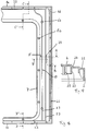
- Fig. 1 is a one-piece frame profile part 1 of Oven door with space for up to three Disc elements from its visible side without any Disc elements shown. Since the disc elements at this embodiment each consist of a disc, is used for the sake of simplicity in the description of "Slices” spoken instead of "slice elements". Of course, the disc elements can also be different be realized.
- An upper frame section 1a can be seen in the figure, a lower frame section 1b, a left frame section 1c and a right frame section 1d.
- the lateral frame sections 1c, 1d have openings 14 - in illustrated embodiment a total of four openings - For one fastener each for fastening a disc.
- Also on the right frame section 1d a formed as a locking recess Door closure element 19 to recognize.
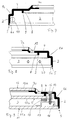
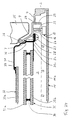
- Fig. 2 shows a section through the upper frame section 1a and the lower frame section 1b along the Line A-A '.
- the upper frame section 1a is described in more detail in FIG. 5.
- Fig. 3 is a section through the left frame section 1c and the right frame section 1d along the Line B-B 'can be seen.
- the left frame section 1c is shown in Fig. 6, the right frame portion 1d in Fig. 8 in more detail described.
- the upper left area of the frame profile part 1 is in Fig. 4 shown as a section.
- the disc bearing agent 6 is the first contact surface 6a and the holding surface 7 designed as a second contact surface 7a.
- a third contact surface 9 can be seen on the possibly existing third disc to lie can come, this washer an washer forms.
- Fig. 5 shows a section through the upper frame section 1a from Fig. 4 along the line A-A '.
- the frame wall 2 with molded-on frame base 4.
- An the visible end face 5 of the frame wall 2 is one first contact surface 6a for the outer pane of the oven door educated.
- the first contact surface 6a is one Recess or recess in the front side 5 of the Frame profile part 1 is formed. It only forms a partial area the end face 5, the support surface 6a, during the Rest of the end face 5 a lateral protrusion Protection of the disc forms.
- the second contact surface 7a is opposite to that oven muffle-side end of the frame profile part 1 in Set back towards the visible side of the oven door.
- the second contact surface is 7a inside the door from the inner pane, not shown arranged.
- spacer 8 On the frame profile part 1 is also in the door interior 3 extending spacer 8 with a third bearing surface 9 available.
- the spacer 8 is the spacer 8 as a one-piece, in the frame profile part 1 circumferential spacer educated.
- the spacer 8 can the support serve a possibly existing third disc, which in this case is an intermediate pane of the oven door forms that between the outer pane and the inner pane is arranged.
- FIG. 6 shows a section through the left frame section 1c from FIG. 4 along the line B-B '.
- the support surfaces 6a, 7a, 9 for the disks are also an opening 14 for a window fastener and a bearing recess 10 for receiving a bearing element to attach the oven door to the oven detect.
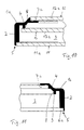
- Fig. 7 Cut an area on the left frame portion 1c outside the opening for a window fastener.
- a door lock member 19 in the form of a Locking recess or for fastening a locking bolt educated. Furthermore, are on the frame profile part 1 two door handle connection elements 20 for attachment of a door handle.
- FIG. 9 shows a section through the right frame section 1d with washers and fasteners
- Outer pane 11a is placed on first contact surface 6a, which is essentially a thickness the amount corresponding to the outer pane 11a is set back inward is.
- On the outer pane 11a is for the Attachment of the disc in the frame profile part 1 Holding element 16 attached, in the illustrated embodiment formed as a bracket 17 with a bore and glued to the disc with an adhesive is.
- the bracket works with a fastener 15 and the one formed on the frame profile part 1 Opening 14 together.
- the fastener 15 is as Realized screw with which the outer disc 11a on the Frame profile part 1 is screwed tight. However, it can other fasteners can be used, such as an elongated extension with a hook-shaped End that in an opening provided on the holding member 16 engages (snap lock).
- the inner pane 12a is from the outside on the second bearing surface 7a placed in and by means of an adhesive the frame profile part 1 glued.
- a third disc which forms an washer 13a and on the third bearing surface 9 rests.
- an elastic Element 18 for clamping the washer 13a arranged.
- the washer 13a is fixed when attaching (e.g. Screwing) the outer pane 11a in the frame profile part 1 clamped.
- To protect the outer pane 11a and Intermediate disk 13a can also be on the first contact surface 6a and the third bearing surface 9 each be arranged elastic element.
- FIG. 10 shows a section through a frame profile part 1 with inserted outer, inner and intermediate plate 11a, 12a, 13a in the area of the upper frame section 1c.
- the trained on the frame bottom 4 second contact surface 7a and that on the front side of the Frame wall 2 formed first support surface 6a around essentially the thickness of the inner pane 12a or Outer pane 11a corresponding amount, based on the Door interior 3, set back inside.
- the disks 12a, 11a only a little protrude beyond the frame profile part 1.
- FIG. 11 shows a variant of this embodiment of a Frame profile part 1 for an oven door according to the invention.
- the second contact surface 7a differs here to the previous variant on the outside of the door from the shown inner pane arranged, i.e. the second Support surface 7a is located on the oven muffle side of the inner pane.
- the described arrangement of the door locking element 19, the at least one bearing recess 10 and the door handle connection element 20 depends crucially on the method of fastening and operating the oven door according to the invention off the oven (e.g. can be swung open to the side, can be opened to the front, attached to a pull-out trolley).
- the first exemplary embodiment was used as an example described an oven door according to the invention, the hinged on the side of the oven and hinged on the left is.
- Figures 12 to 20 show a second embodiment an oven door according to the invention.
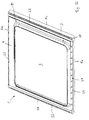
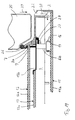
- Fig. 12 is the side facing the oven muffle of a one-piece frame profile part 1 of the oven door shown without disc elements.
- the frame profile part 1 has an upper frame portion 1a, a lower frame portion 1b and side frame sections 1c and 1d on.
- each frame section 1a, 1b, 1c, 1d arranged parallel to the frame wall 2. You are in that Frame profile part 1 all around, i.e. ring-shaped, formed.
- Fig. 13 shows the one-piece frame profile part 1 of its visible side with inserted first disc element 11.
- Fig. 13b shows the ventilation slots 22 recognizable.
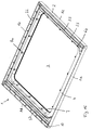
- the frame profile part 1 is without from its visible side used first disc element in Figures 14 and 15, the frame profile part 1 in FIG. 15 is rotated by 180 ° in comparison with that in FIG.
- the frame profile part 1 has one piece molded disk bearing means 6 for the first Disc element, the first disc of which is an outer disc forms on.
- the disk bearing means 6 are each realized as a projection with a hole that is below of the respective opening 14 extends into the door interior.
- Such disk bearing means 6 are in the following as Fastening domes 6b designated.
- the frame profile part 1 also has a holding surface 7 for a second disc element, the second disc forms an inner pane of the oven door. Furthermore is too recognize that the frame profile part 1 is in the door interior 3 extending spacing means 8 for a third Has disc element.
- the spacing means 8 are each as a one-piece projection with a bore realized and each have a bearing surface 9 for the third disc element.
- Such a trained one Spacer 8 is hereinafter referred to as the support dome 8a designated.
- the continuation of the ventilation slots 22 in the door interior 3 is in Fig. 14 for the upper frame portion 1a and the left frame portion 1c, in Fig. 15, for the lower one Frame section 1b and the right frame section 1d recognizable.
- the ventilation system is for example, the ventilation system for external cooling the oven muffle and for cooling the electronic components the oven. Flowing through the door interior 3 Cooling air cools the window elements and the frame wall 2, which reduces the risk that Users, for example when opening the oven door burn the outer pane 11a or the frame wall 2, or the adjacent furniture is damaged.
- cooling fins 23 For improved cooling of the frame wall 2 of the side Frame sections 1c, 1d are on their frame base 4, respectively two cooling fins 23 formed in one piece, which in each case essentially in these frame sections run parallel to the frame wall 2. Through the Ventilation slots 22 entering the door interior 3 Air flows past the cooling fins 23, causing the heat dissipation the frame wall 2 in the area of the side frame sections 1c and 1d is improved.
- the cooling fins 23 can also be designed or arranged differently. Further it may be sufficient just on the frame section, where the door handle is located, at least one cooling fin 23 to be provided. In ovens where none are very high operating temperatures occur or at which others Precautions for heat protection are taken (e.g. Provision of a further pane element, insulation measures), can also do without a cooling fin entirely will.
- the ventilation slots 22 on the Frame profile part 1 are arranged all around. It can be sufficient on one or more frame sections only provide ventilation slots 22 in sections, for example, in order to direct air along the cooling fins 23. Furthermore, the opening cross section of the Vents 22 depending on the arrangement and function of the respective ventilation slots 22 (air inlet, air outlet) different within the frame profile part 1 be great. Overall, the air flow depends on the Door interior 3 from numerous influencing factors, in particular on the type of ventilation system to which the door interior 3 is connected, the number, the dimensions and the arrangement of the ventilation slots 22, the volume of the door interior 3, etc. These influencing factors are known to the expert. He can do it in a common way and Vary the way to get the required air flow (by means of Convection or forced ventilation) through the door interior 3 to realize.
- FIG. 16 shows a section from the right area of the frame profile part 1.
- the right frame section 1d is with adjacent upper frame section 1a as well adjacent lower frame section 1b shown.
- the ventilation slots 22nd are different within the frame profile part 1.
- the ventilation slots in particular 22 on the upper frame portion 1a large cross section, since this frame section when closed Oven door on the pressure side of the fan the oven ventilation system is arranged (see Fig. 19).
- Through the narrower ventilation slots 22 on the right frame section 1d can by in the door interior 3 flowing cooling air secondary air can be sucked in.
- the air occurs essentially through the vents 22 of the lower frame section 1b from the door interior 3.
- the flow path of the cooling air depends on Door interior 3 depends on which side of the oven the pressure side of the ventilation system fan is located, to which the door interior 3 is connected. Consequently, other ventilation slots 22 in the essential to the air inlet or outlet to serve.
- FIG. 17 shows a partial section through the right frame section 1d from Fig. 16.
- the frame wall 2 is in one piece molded onto the frame base 4.
- FIG. 18 shows a section through the right frame section 1d from FIG. 16 with disk elements and disk element fastening means.
- a section of the components is an oven muffle 25 indicated. It can be seen that the frame wall 2 with adjacent frame base 4, the cooling fins 23, the Holding surface 7, the support dome 8a and the mounting dome 6b are integrally formed on the frame profile part 1.
- the holding surface 7 is on the outside of the door from the second Disc element 12, which in this embodiment the second disc 12a is arranged.
- This arrangement the holding surface 7 has the advantage that the assembly the disc elements with the exception of the disc element, that includes the front window of the oven door, from one Direction can take place. This reduces the number the one required to assemble the oven door Handling steps and the risk that the enamelling, Coating or painting the frame profile part 1 at assembly is damaged.
- a door seal 26, for example made of silicone to seal the oven door against the oven muffle 25 is between the second disc 12a and the holding surface 7 held by clamping action.
- the third disc element 13, the third disc 13a forms an intermediate plate of the oven door, includes next the third disc 13a a molded first intermediate plate 13b, which surrounds the intermediate plate 13a like a frame.
- the third washer 13a is in a recess of the first intermediate plate 13b glued. Alternatively could also use fasteners be pinched.
- the first intermediate plate 13b lies on the contact surfaces 9 of the support dome 8a and is with the help of a fastener attached to them.
- a fastener screws are used for the third disk element 13 27, preferably self-tapping screws, the Shaft through a hole in the first intermediate plate 13b extends and into the support domes 8a are screwed in.
- the screws 27 are preferably also used for Attachment of the second disc element 12.
- To this Purpose are holding brackets 28 provided with a bore provided through openings in the first intermediate plate Reach through 13b.
- To attach the second and third disc elements 12 and 13 are the brackets 28 and the first intermediate plate 13b by means of the screws 27 screwed onto the support domes 8a, each the shaft of a screw 27 through a hole in the Bracket 28 and through a hole in the first intermediate plate 13b engages.
- One end of the Bracket 28 against the edge of the second disc 12a the door seal 26 and this against the holding surface 7.
- each has a bracket 26 with a fastener and one on the frame profile part 1 trained opening 14, which Fasteners advantageously also here Screw is realized.
- One screw is from the side of the frame profile part facing the oven muffle 1 inserted into an opening 14. It extends it through the bore of the mounting dome 6b and is screwed into the bracket 17.
- Im used and screwed state is the first Disk 11a preferably does not open in its edge region the frame wall 2, but is on the bracket 17th supported on the mounting domes 6b.
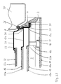
- FIG. 19 shows a section through the upper frame section 1a with inserted disc elements 11, 12, 13 and disk element fasteners the oven door on the oven arranged such that the ventilation slots 22 on the indicated by an arrow 29 Pressure side of a fan of a ventilation system are arranged. Cooling air passes through the ventilation slot 22, whose flow path is illustrated by an arrow 30 is in the door interior 3. With this cut is the hole in the support dome 8a, in which the Screw 27 is screwed in, can be seen.
- the minimum frame thickness for a frame profile part made of die-cast aluminum is preferably at least 0.5 mm, preferably at least 1.0 mm.
- Typical wall thicknesses for cast aluminum are 1.5 mm to 3 mm; larger wall thicknesses up to 10 mm and more are possible.
- Oven doors essentially for ovens without pyrolytic self-cleaning are suitable.
- Such Doors are for ovens with pyrolytic self-cleaning less preferred because temperatures up to during pyrolysis occur at 500 ° C, at which the frame profile part and the disc elements of the previously described embodiments can heat up too much.
- FIGS A third preferred embodiment is shown in FIGS described the oven door according to the invention, for an oven with pyrolytic self-cleaning suitable is.
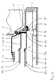
- the cut positions correspond to Figures the cut positions shown in Fig. 16 for the second embodiment. 21 thus shows one Section through the right frame section 1d, FIG. 22 a section through the upper frame portion 1a ( however no ventilation slot 22 is cut) and Fig. 23 shows a section through the lower frame section 1b.
- a heat protection frame 31 In contrast to the construction of the oven door according to the second embodiment is on the frame profile part 1 Oven-side a heat protection frame 31 with a fourth disk element 32 in the form of a fourth disk 32a arranged.
- the fourth disc 32a is on the heat protection frame 31, which is made of enamelled sheet metal, preferably clamped by means of holding elements. she however, could also be glued or otherwise attached be. Between the fourth disc 32a and the heat protection frame 31 there is a glass fiber seal 33.
- the second disc element comprises 12 a second disc 12a and a frame-like one second intermediate plate 12b with a circumferential recess, into which the second disc 12a is inserted and there is stuck.
- the heat protection frame 31 is in the Frame profile part 1 held by clamping action by its edge 36 between the door seal 26 and the edge of the second intermediate plate 12b is arranged.
- the ends of the Bracket 28 thus hold the second intermediate plate 12b, the edge 36 of the heat protection frame 31 and the door seal 26 pressed against the holding surface 7. Otherwise corresponds the structure of the oven door that of Figures 12 to 20.
- other options are possible, around the heat protection frame 31 and the second pane element 12 to be fixed in the frame profile part 1.
- An advantageous variant can, for example, be in it exist that the second disc 12a and the third Disc 13a, or the second disc element 12 and that third disc element 13 represent a composite structure and be attached together. 24 is an embodiment explained.
- FIG. 24 shows a section through the left frame section 1d on a section corresponding to section B-B 'from FIG. 16 Place of a fourth embodiment of the invention, namely an oven door with a heat protection frame.
- This embodiment differs from the third Embodiment essentially through the structure and Assembly of the between the further disc element 32 of the Heat protection frame 31 and the first pane element 11 arranged washers.
- Form the washers here another disc element 35 in the form of a Disc packs with two arranged parallel to each other Disks 35a, 35b. They are around the edge with help an adhesive 34 made of a temperature-resistant adhesive (e.g. silicone adhesive) bonded together, with the help of a spacer, not shown kept apart from each other.
- a temperature-resistant adhesive e.g. silicone adhesive
- the Discs 35a, 35b of the further disc element 35 correspond thus the second disc 12a and the third Disk 13a in that shown in Figures 21 to 23 Embodiment.
- the disc package is on a frame-like another intermediate plate 35c of the further disk element 35 glued on. Of course it could too be clamped with the help of fasteners.
- the another intermediate plate 35c is the same as the first Intermediate plate 13b screwed to the support dome 8a, the bracket 28 in this embodiment Edge 36 of the heat protection frame 31 and the door seal 26 presses against the holding surface 7. Otherwise corresponds to Structure of the oven door that of FIGS. 21 to 23 described oven door.
- a disc element with a disc package could also be used an embodiment without a heat protection frame advantageous can be used to reduce the assembly effort.
- the number of disks 11a, 12a, 13a, 32a, 35a, 35b of the Disc elements 11, 12, 13, 32, 35 and their arrangement have within the frame profile part 1 among others Influence on the temperature at the first disc 11a first disc element 11, which forms an outer disc, and the temperature on the frame wall 2. This temperature should preferably be less than 80 ° C.
- the intervals are self-cleaning between the first disc 11a of the first disc element 11 and the third disc 13a of the third disc element 13 advantageously 0.3 cm to 2.5 cm and between the third disc 13a of the third disc element 13 and the second disc 12a of the second disc element 12 advantageously 0.2 cm to 2.0 cm.
- the distance between the fourth Washer 32a of the heat protection frame 31 and the second Disc 12a of the second disc element 12 advantageously 0.3 cm to 2.5 cm.
- the distances between the Discs of the other disc elements correspond to essentially the one above for an oven door without a heat protection frame distances mentioned. With an oven door with heat protection frame 31 and further pane element 35 with disc package, the distances mentioned in essentially accordingly.
Abstract
Description
Die Erfindung betrifft eine Backofentür für einen Backofen mit Backofenmuffel, wobei die Backofentür einen rahmenartigen Träger zum Einfassen mindestens eines Scheibenelements aufweist und der rahmenartige Träger einen Rahmenboden und seitliche Einfassungsleisten, die eine einen Türinnenraum umgrenzende Rahmenwand bilden, umfaßt. Dabei bildet der Rahmenboden eine der Backofenmuffel zugewandte Innenwand des rahmenartigen Trägers.The invention relates to an oven door for an oven with oven muffle, the oven door being a frame-like Carrier for enclosing at least one pane element has and the frame-like carrier one Frame bottom and side edging strips, one form a frame wall defining the door interior. The frame base forms one facing the oven muffle Inner wall of the frame-like carrier.
Backofentüren mit einer außen gelegenen, sichtseitigen Außenscheibe und zumeist einer zusätzlichen backofenmuffel-seitigen Innenscheibe sind in mehreren Ausführungsformen bekannt. Der rahmenartige Träger zum Einfassen der mindestens einen Scheibe ist bei bekannten Türen aus mehreren Einzelteilen zusammengesetzt. Diese Einzelteile umfassen als tragendes Grundelement einen Rahmenboden, der, bezogen auf die an den Backofen montierte fertige Tür, zumeist eine backofenmuffel-seitig angeordnete rahmenartige Innenwand der Backofentür bildet. Der Rahmenboden ist in der Regel ein als Füllplatte ausgebildeter Sicht- und Tragerahmen, der der Aufnahme einer Scheibe dient. Die Füllplatte ist in der Regel im wesentlichen eben. Dies ist jedoch nicht zwingend erforderlich, sie kann auch strukturiert oder profiliert sein. Die Füllplatte wird auch als Türfüllblech bezeichnet und ist vorzugsweise emailliert.Oven doors with an external, visible side Outer pane and mostly an additional oven muffle side Inner pane are in several embodiments known. The frame-like carrier for mounting the at least one pane is in known doors composed of several individual parts. These items comprise a frame floor as a load-bearing basic element, the, based on the one mounted on the oven finished door, usually a muffle on the oven side forms the frame-like inner wall of the oven door. Of the The frame base is usually a filling plate Viewing and carrying frame, which can hold a Disc serves. The filler plate is usually essentially just. However, this is not absolutely necessary it can also be structured or profiled. The Filling plate is also called and is a door filler plate preferably enamelled.
An der Füllplatte sind seitlich mit Hilfe von Schrauben mehrere als Winkelleisten ausgebildete Einfassungsleisten angebracht, die eine einen Türinnenraum umgrenzende Rahmenwand mit einer sichtseitigen Stirnseite bilden und die mindestens eine Scheibe einfassen. Als Türinnenraum ist dabei der innerhalb des rahmenartigen Tägers gelegene Raum zwischen der Innen- und der Außenscheibe zu verstehen. Die Einfassungsleisten bestehen zumeist aus Aluminiumstrangpreßprofilen.On the filler plate are on the side with the help of screws several edging strips designed as angle strips attached, the frame wall surrounding a door interior form with a face side and the Hold at least one pane. As a door interior is the one located within the frame-like carrier To understand space between the inner and the outer pane. The edging strips mostly consist of extruded aluminum profiles.
Des weiteren sind separate Halterungen für die Scheiben und Befestigungselemente vorgesehen, um die Scheiben in dem rahmenartigen Träger zu positionieren und zu befestigen. Dabei wird die Außenscheibe vorzugsweise mit innenliegenden Befestigungselementen an dem rahmenartigen Träger befestigt, um sie unaufwendig den jeweiligen Designanforderungen anpassen zu können. Die Innenscheibe ist durch die an der Füllplatte befestigten seitlichen Einfassungsleisten festgeklemmt. Sie kann jedoch auch in den rahmenartigen Träger eingeklebt sein.There are also separate brackets for the panes and fasteners provided to secure the washers in to position and fasten the frame-like carrier. The outer pane is preferably with the inside Fastening elements on the frame-like carrier attached to them to the respective design requirements to be able to adapt. The inner pane is through the side edging strips attached to the filler plate clamped. However, you can also in the frame-like carrier glued.
Ferner können bei bekannten Backofentüren im Bereich der Rahmenwand zusätzliche Abdeckleisten angebracht sein, um den ästhetischen Gesamteindruck der aus vielen Einzelteilen zusammengesetzten Tür zu vereinheitlichen.Furthermore, in known oven doors in the area of Frame wall additional cover strips may be attached to the overall aesthetic impression of many individual parts unify compound door.
Aus der EP 0151359 A1 ist eine aus vielen Einzelteilen gefertigte Backofentür mit zwei Scheiben bekannt. Sie weist einen Rahmen auf, der zwei seitliche, zwischen den Scheiben angeordnete, vertikale Streben sowie eine obere und eine untere Querstrebe hat. Die untere und obere Querstrebe halten die zwei Scheiben gegen die seitlichen, vertikalen Streben gedrückt.EP 0151359 A1 is one of many individual parts manufactured oven door with two panes known. she has a frame, the two side, between the Disc-arranged, vertical struts and an upper one and has a lower cross strut. The lower and upper Cross brace hold the two washers against the side, vertical struts pressed.
Aufgrund der hohen Anzahl von Einzelteilen sind die herkömmlichen Backofentüren konstruktiv aufwendig und erfordern einen hohen Montageaufwand, weshalb sie in der Herstellung teuer sind.Due to the high number of individual parts, the conventional ones Oven doors are structurally complex and require a high assembly effort, which is why they are in the manufacture are expensive.
Außerdem sind Backofentüren bekannt, die ein Rahmenprofilteil aus umgeformtem, zum Beispiel tiefgezogenem, Blech aufweisen, an dem die Rahmenwand und der Rahmenboden einstückig ausgebildet sind. Derartige Rahmenprofilteile haben den Nachteil, daß sie sich sehr leicht verziehen. Ferner sind der Profilform aufgrund der Umform-Fertigungstechnik enge gestalterische Grenzen gesetzt. Darüber hinaus müssen für die Montage der Backofentür zusätzliche Befestigungselemente in das Rahmenprofilteil eingeschweißt werden. Der Fertigungs- und Montageaufwand derartiger Backofentüren ist somit sehr groß.In addition, oven doors are known which are a frame profile part from formed, for example deep-drawn, Have sheet metal on which the frame wall and the frame base are integrally formed. Such frame profile parts have the disadvantage that they are very easy warp. Furthermore, the profile shape due to the forming manufacturing technology set narrow design limits. You also need to install the oven door additional fastening elements in the frame profile part be welded in. The manufacturing and assembly effort Such oven doors are therefore very large.
Die Erfindung geht daher von der Aufgabenstellung aus, eine Backofentür zu schaffen, die vergleichsweise wenige Einzelteile aufweist, kostengünstig herzustellen und einfach zu montieren ist. Dabei soll die Backofentür ein ansprechendes Design ermöglichen.The invention is therefore based on the task, to create an oven door that is comparatively few Has individual parts, inexpensive to manufacture and simple is to be assembled. The oven door should be appealing Enable design.
Die Aufgabe wird erfindungsgemäß dadurch gelöst, daß bei einer eingangs genannten Backofentür die Rahmenwand und der Rahmenboden ein einstückiges Rahnmenprofilteil des rahmenartigen Trägers bilden und das Rahmenprofilteil im wesentlichen durch Urformen oder Fräsen gefertigt ist.The object is achieved in that at an oven door mentioned above the frame wall and the frame base is a one-piece Rahnmenprofilteil the form frame-like carrier and the frame profile part in is essentially made by master shaping or milling.
Die erfindungsgemäße Backofentür weist als Grundelement des rahmenartigen Trägers ein einstückiges Rahmenprofilteil auf, an dem weitere Elemente der Tür angebracht bzw. ausgebildet sein können. Durch das erfindungsgemäße Rahmenprofilteil entfällt die bei herkömmlichen Türen erforderliche gesonderte Montage der Einfassungsleisten. Darüber hinaus kann auch auf die Abdeckungsleisten verzichtet werden. Somit sind durch die erfindungsgemäße Bauweise für das Zusammensetzen einer Backofentür weniger Einzelteile und Arbeitsschritte erforderlich. Dadurch verringert sich der Montageaufwand, so daß die Tür kostengünstiger fertigbar ist. Gleichzeitig ist die Stabilität erhöht und das Design gefälliger.The oven door according to the invention has a basic element the frame-like carrier is a one-piece frame profile part on which other elements of the door are attached or can be trained. Through the frame profile part according to the invention the necessary with conventional doors is eliminated separate mounting of the edging strips. About that the cover strips can also be dispensed with will. Thus, by the construction according to the invention Fewer individual parts for assembling an oven door and work steps required. This reduces the assembly effort, so that the door is cheaper is producible. At the same time, the stability increased and the design more pleasing.
Unter "Urformen" wird das Herstellen eines Formteils aus einem formlosen Ausgangsstoff (zum Beispiel Granulat, Schmelze, Pulver etc.) verstanden. Dazu wird der formlose Ausgangsstoff in ein spezielles Urformwerkzeug eingebracht (zum Beispiel gegossen, gepreßt), in dem es durch Erstarren, Sintern usw. in den festen Zustand übergeht. Das auf diese Weise gebildete Formteil, hier das Rahmenprofilteil, wird dem Urformwerkzeug entnommenUnder "master forms" is the manufacture of a molded part an informal raw material (e.g. granules, Melt, powder, etc.) understood. This is the informal The raw material is brought into a special master mold (for example, poured, pressed) in which it goes through Solidification, sintering etc. changes into the solid state. The molded part formed in this way, here the frame profile part, is taken from the master mold
Durch den Fertigungsprozeß hat das Rahmenprofilteil weitgehend die für die Backofentür erforderliche Gestalt und eine hohe Maßgenauigkeit, wodurch die Anzahl von Nachbearbeitungsschritten reduziert wird. Ferner ist es möglich, technisch vorteilhafte und ästhetisch gewünschte Profilformen an dem Rahmenprofil zu realisieren, die bei aus Einzelteilen montierten Backofentüren nicht oder nur mit sehr hohem Aufwand möglich sind. Darüber hinaus kann die Materialstärke innerhalb des Rahmenprofilteils variieren und den jeweiligen Erfordernissen angepaßt werden. Unter anderem aus diesem Grund ist bei der erfindungsgemäßen Backofentür die Gefahr, daß sie sich verzieht, verringert. Ebenso können ohne hohen Zusatzaufwand weitere Elemente für den Zusammenbau der Backofentür und deren Montage an dem Backofen einstückig an dem Rahmenprofilteil ausgebildet sein, um den Montageaufwand weiter zu reduzieren. Die genannten Vorteile können auch bei einer Backofentür mit einem gefrästen Rahmenprofilteil erreicht werden.Due to the manufacturing process, the frame profile part has largely the shape required for the oven door and high dimensional accuracy, reducing the number of post-processing steps is reduced. It is also possible technically advantageous and aesthetically desired Realize profile shapes on the frame profile, which at Oven doors not assembled or only from individual parts are possible with a great deal of effort. Furthermore, can the material thickness vary within the frame profile part and be adapted to the respective requirements. For this reason, among other things, the invention Oven door reduces the risk of warping. Likewise, more can be done without high additional effort Elements for the assembly of the oven door and their Installation on the oven in one piece on the frame profile part be designed to further increase the assembly effort to reduce. The advantages mentioned can also apply to a Oven door reached with a milled frame profile part will.
Ferner ist die erfindungsgemäße Backofentür aufgrund der durch das einstückige Rahmenprofilteil bedingten geringeren Anzahl von Nuten und Schlitzen leichter zu reinigen. Durch die Einstückigkeit des Rahmenprofilteiles und seine Realisierung als Formteil ist es zudem möglich, Ecken und Kanten abzurunden, um den ästhetischen Gesamteindruck zu verbessern bzw. variabel zu gestalten sowie die Gebrauchssicherheit zu erhöhen.Furthermore, the oven door according to the invention is due to the due to the one-piece frame profile part less Number of grooves and slots easier to clean. Due to the one-piece of the frame profile part and its Realization as a molded part, it is also possible to create corners and Round off edges to create an overall aesthetic impression improve or make it variable as well as safety in use to increase.
Das einstückige Rahmenprofilteil weist einen oberen, unteren, linken und rechten Rahmenabschnitt auf. Im geschlossenen Zustand der an den Backofen montierten Backofentür weist eine an der Rahmenwand des Rahmenprofilteiles ausgebildete sichtseitige Stirnseite nach außen, während der Rahmenboden eine backofenmuffelseitige, d.h. dem Backofen zugewandte, Innenwand des rahmenartigen Trägers bildet.The one-piece frame profile part has an upper, lower, left and right frame sections. In the closed Condition of the oven door installed on the oven has one on the frame wall of the frame profile part trained face side to the outside, while the frame floor is an oven muffle-side, i.e. the oven facing inner wall of the frame-like carrier forms.
Zur weiteren Reduktion der Anzahl der Einzelteile kann es vorteilhaft sein, wenn weitere Türbauelemente, wie beispielsweise eine Halterung für ein Scheibenelement, an dem einstückigen Rahmenprofilteil ausgebildet sind.It can be used to further reduce the number of individual parts be advantageous if other door components, such as a holder for a disc element the one-piece frame profile part are formed.
Nach einem ersten vorteilhaften Merkmal weist das Rahmenprofilteil ein Scheibenlagermittel für ein erstes Scheibenelement auf.According to a first advantageous feature, the frame profile part a disc bearing means for a first Disc element on.
Nach einem zweiten vorteilhaften Merkmal weist das Rahmenprofilteil eine Haltefläche für ein zweites Scheibenelement auf. Dabei ist die Haltefläche bevorzugt an dem Rahmenboden des Rahmenprofilteils ausgebildet.According to a second advantageous feature, the frame profile part a holding surface for a second disc element on. The holding surface is preferably on the Frame bottom of the frame profile part formed.
Zur besseren thermischen Isolierung, beispielsweise bei Backöfen mit katalytischer Reinigung, kann die Backofentür ein drittes Scheibenelement aufweisen. Daher kann es vorteilhaft sein, wenn das Rahmenprofilteil mindestens ein sich in den Türinnenraum erstreckendes Abstandsmittel für ein auf einer Auflagefläche aufgelegtes drittes Scheibenelement aufweist. Dabei kann die Auflagefläche an dem mindestens einen Abstandsmittel ausgebildet sein. Das mindestens eine Abstandsmittel kann bevorzugt einstückig an dem Rahmenprofil angeformt sein, beispielsweise als Abstandssteg oder als vorspringender Teil, der im folgenden als "Auflagedom" bezeichnet wird. Dabei ist die Auflagefläche bevorzugt derart angeordnet, daß das dritte Scheibenelement zwischen dem ersten Scheibenelement und dem zweiten Scheibenelement liegt.For better thermal insulation, for example at Ovens with catalytic cleaning, the oven door can have a third disc element. Therefore it can be advantageous if the frame profile part at least a spacer extending into the door interior for a third placed on a support surface Has disc element. The contact surface can the at least one spacer can be formed. The at least one spacer can preferably be in one piece be molded onto the frame profile, for example as Spacer or as a protruding part, the following is referred to as a "support dome". Here is the Contact surface preferably arranged such that the third Disc element between the first disc element and the second disc element.
Ein Scheibenelement kann in Abhängigkeit von seiner Anordnung innerhalb des Rahmenprofilteils und dessen Ausführung unterschiedlich gestaltet sein: Es kann im wesentlichen nur aus einer Scheibe, die in dem Rahmenprofilteil direkt befestigt wird, gebildet sein. In einer anderen Variante umfaßt ein Scheibenelement im wesentlichen eine Scheibe und einen Zwischenträger (im folgenden als "Zwischenblech" bezeichnet), der die Scheibe rahmenartig umgibt. Auch mehrere voneinander beabstandete, randlich miteinander verbundene Scheiben können - gegebenenfalls mit einem Zwischenblech verbunden - ein Scheibenelement bilden.A disc element can, depending on its arrangement within the frame profile part and its execution can be designed differently: it can essentially only from a disc in the frame profile part is attached directly, be formed. In a another variant essentially comprises a disc element a disc and an intermediate beam (hereinafter referred to as "intermediate plate"), which the disc frame-like surrounds. Also several spaced apart marginally connected disks can - if necessary connected with an intermediate plate - a disc element form.
Die Scheiben können auf unterschiedliche Art und Weisen in der Backofentür befestigt sein. In einer ersten Ausführung können eine oder mehrere Scheiben, zum Beispiel die Scheibe des zweiten Scheibenelements, mittels eines Klebstoffs in das Rahmenprofilteil oder in ein entsprechendes Zwischenblech, das in dem Rahmenprofilteil befestigt wird, eingeklebt sein. Der verwendete Klebstoff sollte relativ hitzebeständig sein. Kleber auf Silikonbasis und temperaturbeständige Zweikomponenten-Kleber können hierfür geeignet sein.The discs can be in different ways be fastened in the oven door. In a first version can be one or more slices, for example the disc of the second disc element, by means of a Adhesive in the frame profile part or in a corresponding Intermediate plate, which is fastened in the frame profile part will be glued in. The adhesive used should be relatively heat resistant. Silicone-based adhesive and temperature-resistant two-component adhesive can be suitable for this.
In einer anderen bevorzugten Ausführung weist das Rahmenprofilteil mindestens eine Öffnung zum Befestigen eines Scheibenelements mittels eines Befestigungsmittels auf.In another preferred embodiment, the frame profile part has at least one opening for attaching a Disc element by means of a fastener.
Das Rahmenprofilteil kann ferner ein Türverschlußelement aufweisen, das mit einer Türverschlußeinrichtung des Backofens zusammenwirkt. Das Türverschlußelement kann beisielsweise als Verschlußaussparung realisiert sein, in die ein backofenseitig vorgesehener Verschlußvorsprung, z.B. ein Türverschlußbolzen oder Rastbolzen, eingreift, um die Backofentür geschlossen zu halten.The frame profile part can also be a door locking element have that with a door locking device of Oven interacts. The door locking element can be realized as a closure recess, for example which has a locking projection provided on the oven side, e.g. a door locking bolt or locking bolt engages, to keep the oven door closed.
Darüber hinaus kann insbesondere bei einem Backofen mit pyrolytischer Selbstreinigung an dem Rahmenprofilteil ein Türverriegelungselement ausgebildet sein, das mit einer Verriegelungseinrichtung des Backofens zusammenwirkt. Das Türverriegelungselement kann beispielsweise als schlitzförmige Verriegelungsöffnung ausgebildet sein, in die ein backofenseitig vorgesehenes Riegelelement, beispielsweise ein beweglicher Haken, eingreift, um die Backofentür, insbesondere während einer pyrolytischen Selbstreinigung des Backofens, so zu verriegeln, daß sie nicht geöffnet werden kann.In addition, with an oven in particular pyrolytic self-cleaning on the frame profile part Door locking element can be formed with a Interlocking device of the oven interacts. The Door locking element can, for example, as a slot-shaped Locking opening to be formed in the locking element provided on the oven side, for example a movable hook that engages around the oven door, especially during pyrolytic self-cleaning lock the oven so that it does not open can be.
Ebenso kann das Rahmenprofilteil ein Türgriffanschlußelement, beispielsweise zwei Befestigungslöcher, aufweisen, um den Türgriff ohne konstruktiven Aufwand an der Tür zu befestigen oder zu integrieren. Ein Türgriff kann auch einstückig an dem Rahmenprofilteil ausgebildet sein.Likewise, the frame profile part can be a door handle connection element, for example, have two mounting holes, around the door handle without any design effort on the door attach or integrate. A door handle can too be integrally formed on the frame profile part.
Bei Backofentüren für Backöfen mit sehr hohen Betriebstemperaturen - insbesondere für Geräte mit pyrolytischer Selbstreinigung, bei denen Temperaturen bis zu 500 °C erreicht werden können - ist es bevorzugt, wenn an dem Rahmenprofilteil backofenmuffel-seitig ein Hitzeschutzrahmen angeordnet ist, der ein viertes Scheibenelement einfaßt. Der Hitzeschutzrahmen hat die Aufgabe, insbesondere beim Pyrolysebetrieb die Backraumtemperatur zu halten und die weiter außen liegenden Scheibenelemente vor der Hitze zu schützen. Der Hitzeschutzrahmen ist vorzugsweise aus emailliertem Blech gefertigt. Das vierte Scheibenelement kann auf unterschiedliche Weise an dem Hitzeschutzrahmen befestigt sein, zum Beispiel geklebt sein oder mit Hilfe eines Befestigungsmittels durch Klemmwirkung gehalten werden.For oven doors for ovens with very high operating temperatures - Especially for devices with pyrolytic Self-cleaning at which temperatures reach up to 500 ° C can be - it is preferred if on the frame profile part on the oven muffle side a heat protection frame is arranged, which surrounds a fourth disc element. The heat protection frame has the task, especially when Pyrolysis to maintain the baking chamber temperature and the disc elements located further out from the heat protect. The heat protection frame is preferably made of enamelled sheet. The fourth disc element can be attached to the heat protection frame in different ways be fixed, for example glued or with the help a fastener held by clamping action will.
Eine weitere bevorzugte Weiterbildung des Rahmenprofilteiles der erfindungsgemäßen Backofentür kann darin bestehen, daß das Rahmenprofilteil mindestens eine Lüftungsöffnung aufweist, um beim Betrieb des Backofens insbesondere das sichtseitige erste Scheibenelement und die Rahmenwand zu kühlen. Auf diese Weise kann bei einer Backofentür mit Hitzeschutzrahmen und insgesamt vier Scheibenelementen erreicht werden, daß die äußere Oberflächentemperatur der Scheibe des ersten Scheibenelements bei sehr hohen Backraumtemperaturen von ca. 500 °C im wesentlichen 78 °C nicht überschreitet. Die mindestens eine Lüftungsöffnung kann beispielsweise loch- oder schlitzförmig ausgebildet sein. Bevorzugt weist das Rahmenprofilteil mehrere Lüftungsöffnungen auf, die im wesentlichen parallel zu einem Abschnitt oder mehreren Abschnitten der Rahmenwand angeordnet sind. Vorteilhafterweise können die Lüftungsöffnungen zur Innenbelüftung der Backofentür an ein backofenseitiges Lüftungssystem angeschlossen sein.Another preferred development of the frame profile part the oven door according to the invention can consist in that the frame profile part has at least one ventilation opening has to in particular when operating the oven the visible first disc element and the Cool the frame wall. In this way, at a Oven door with heat protection frame and a total of four Disk elements are achieved that the outer surface temperature the disc of the first disc element at very high baking chamber temperatures of approx. 500 ° C in substantially does not exceed 78 ° C. The least a ventilation opening can for example be perforated or be slit-shaped. The frame profile part preferably has several vents on that essentially parallel to a section or several sections the frame wall are arranged. Advantageously can use the ventilation openings for indoor ventilation the oven door to a ventilation system on the oven side be connected.
Beim Betrieb des Backofens, insbesondere beim Pyrolysebetrieb, kann es trotz Innenbelüftung an den seitlichen Bereichen und den Ecken des Türinnenraums zu einem Wärmestau kommen. Dies kann, wie auch die Wärmeleitung durch den Profilrahmen selbst, dazu führen, daß sich die seitlichen Abschnitte der Rahmenwand mehr als gewünscht erhitzen. Zum Kühlen eines Abschnitts der Rahmenwand, insbesondere an der Seite, an der sich der Türgriff befindet, weist das Rahmenprofilteil vorzugsweise mindestens eine sich in den Türinnenraum erstreckende und im wesentlichen parallel zu dem Abschnitt der Rahmenwand verlaufende Kühlrippe auf. Die mindestens eine Kühlrippe wird durch Luft, die zur Belüftung des Türinnenraums in diesen einströmt, gekühlt und bewirkt dadurch eine verbesserte Kühlung des betreffenden Abschnitts der Rahmenwand. Für einen verbesserten Wärmeübergang und zur Verminderung des konstruktiven Aufwands ist die Kühlrippe an dem Rahmenprofilteil bevorzugt einstückig ausgebildet.When operating the oven, especially during pyrolysis, despite internal ventilation on the side Areas and the corners of the door interior to a heat build-up come. This can, like heat conduction the profile frame itself, cause the side Heat sections of the frame wall more than desired. For cooling a section of the frame wall, in particular on the side where the door handle is located, preferably has at least the frame profile part one extending into the door interior and essentially extending parallel to the section of the frame wall Cooling fin on. The at least one cooling fin will through air used to ventilate the door interior in this flows in, cooled and thereby brings about an improved Cooling the relevant section of the frame wall. For an improved heat transfer and to reduce the design effort is the cooling fin on the frame profile part preferably formed in one piece.
Die erfindungsgemäße Backofentür kann sowohl an einem Auszugswagen für ein Backblech als auch an einem Klappscharnier oder -gelenk befestigbar sein. Im zuletzt genannten Fall ist an dem Rahmenprofilteil vorzugsweise mindestens eine Lageraussparung ausgebildet, die ein Lagerelement, beispielsweise eine Lagerbuchse, aufnimmt, so daß die Sackofentür an der Frontseite des Backofens schwenkbar befestigt werden kann, wobei die Drehachse insbesondere vertikal oder horizontal orientiert sein kann. The oven door according to the invention can both on one Pull-out trolley for a baking sheet as well as on a folding hinge or joint can be attached. In the latter Case is preferred on the frame profile part formed at least one bearing recess, which is a bearing element, for example, a bearing bushing, so that the pocket oven door on the front of the oven can be pivotally attached, the axis of rotation in particular be oriented vertically or horizontally can.
Nach einer bevorzugten Ausführung der Backofentür ist das einstückige Rahmenprofilteil im wesentlichen aus Metall gefertigt, das bevorzugt emailliert, lackiert oder beschichtet ist. Als vorteilhafter Werkstoff für das Rahmenprofilteil hat sich Aluminium erwiesen, da es ein geringes Gewicht und eine hohe Stabilität aufweist sowie kostengünstig und unproblematisch zu bearbeiten ist. Das metallene Rahmenprofilteil kann bevorzugt im wesentlichen als Druckguß ausgebildet sein. Mittels des Druckguß-Verfahrens hergestellte Rahmenprofilteile sind kostengünstig und können in vielen unterschiedlichen Formen gefertigt werden.According to a preferred version of the oven door, this is one-piece frame profile part essentially made of metal manufactured, which is preferably enamelled, painted or coated is. As an advantageous material for the frame profile part aluminum has proven to be a minor one Weight and high stability as well is inexpensive and easy to process. The metal frame profile part can preferably essentially be designed as a die casting. By means of the die casting process manufactured frame profile parts are inexpensive and can be made in many different shapes will.
Alternativ kann das Rahmenprofilteil im wesentlichen aus Kunststoff gefertigt sein. Die hierfür geeigneten Kunststoffe müssen bei relativ hohen Temperaturen beständig sein. Dabei kann eine zwischen dem Rahmenboden und der Backofenmuffel angeordnete Türdichtung, beispielsweise aus Silikon, eine Isolierung bewirken, so daß die auf das Rahmenprofilteil einwirkende Temperatur niedriger als die Backraumtemperatur ist. Als geeignete Kunststoffe erscheinen insbesondere PPS oder PEEK, die bis zu einer Temperatur von ca. 260 °C beständig sind. Diese Temperatur wird jedoch, bedingt durch die Silikondichtung, im Bereich des Rahmenprofilteiles nicht erreicht. Ein Rahmenprofilteil läßt sich aus Kunststoff beispielsweise im Spritzgußverfahren in hoher Stückzahl, kostengünstig und in vielen unterschiedlichen Formen herstellen.Alternatively, the frame profile part can consist essentially of Be made of plastic. The suitable plastics for this must be stable at relatively high temperatures be. One can be between the frame floor and the Oven muffle arranged door seal, for example made of silicone, cause insulation so that the on the Frame profile part acting temperature lower than that Baking chamber temperature is. Appear as suitable plastics especially PPS or PEEK, up to one Temperature of approx. 260 ° C are stable. That temperature is, however, due to the silicone seal in Area of the frame profile part not reached. A frame profile part can be made of plastic, for example Injection molding process in large numbers, inexpensive and produce in many different shapes.
Vorzugsweise umfassen die Scheibe des zweiten Scheibenelements (zweite Scheibe), die bei einer Backofentür ohne Hitzeschutzrahmen eine Türinnenscheibe bildet, die Scheibe des gegebenenfalls vorhandenen dritten Scheibenelements (dritte Scheibe), die eine Türzwischenscheibe bildet, und die eine Türaußenscheibe bildende Scheibe des ersten Scheibenelements (erste Scheibe) gehärtetes, beschichtetes, gegebenenfalls mit einem Dekor bedrucktes und geformtes Flachglas. Die vierte Scheibe eines gegebenenfalls vorhandenen Hitzeschutzrahmens umfaßt bevorzugt Borosilikatglas.Preferably include the disc of the second disc element (second pane) without an oven door Heat protection frame forms a door inner pane, the pane the third disc element, if present (third pane), which forms a door intermediate pane, and the pane of the first disc element (first disc) hardened, coated, optionally printed with a decor and shaped flat glass. The fourth slice of one if necessary existing heat protection frame preferably includes Borosilicate glass.
Die folgenden Ausführungsbeispiele der Erfindung lassen weitere vorteilhafte Merkmale und Besonderheiten erkennen, die anhand der schematischen Darstellungen in den Zeichnungen im folgenden näher beschrieben und erläutert werden.Let the following embodiments of the invention recognize other advantageous features and special features, the based on the schematic representations in the Drawings described and explained in more detail below will.
Es zeigen:
- Fig. 1
- eine sichtseitige Aufsicht auf ein einstückiges Rahmenprofilteil gemäß einer ersten bevorzugten Ausführungsform der Erfindung,
- Fig. 2
- einen Schnitt A-A' zu Fig. 1,
- Fig. 3
- einen Schnitt B-B' zu Fig. 1,
- Fig. 4
- einen Detailausschnitt aus dem oben links gelegenen Rahmenabschnitt von Fig. 1,
- Fig. 5
- einen Schnitt A-A' zu Fig. 4,
- Fig. 6
- einen Schnitt B-B' zu Fig. 4,
- Fig. 7
- einen ersten Detailschnitt aus dem linken Rahmenabschnitt des Rahmenprofilteiles von Fig. 1,
- Fig. 8
- einen zweiten Detailschnitt aus dem rechten Rahmenabschnitt des Rahmenprofilteiles von Fig. 1,
- Fig. 9
- einen dritten Detailschnitt aus dem rechten Rahmenabschnitt des Rahmenprofilteiles (mit Scheiben) von Fig. 1,
- Fig. 10
- einen vierten Detailschnitt aus dem oberen Rahmenabschnitt des Rahmenprofilteiles (mit Scheiben) von Fig. 1,
- Fig. 11
- einen fünften Detailschnitt aus dem unteren Rahmenabschnitt des Rahmenprofilteiles (ohne Scheiben) von Fig. 1,
- Fig. 12
- eine backofenmuffel-seitige perspektivische Aufsicht auf ein einstückiges Rahmenprofilteil gemäß einer zweiten bevorzugten Ausführungsform der Erfindung,
- Fig. 13
- eine sichtseitige perspektivische Aufsicht auf das Rahmenprofilteil von Fig. 12 mit eingesetztem ersten Scheibenelement,
- Fig. 14
- eine sichtseitige perspektivische Aufsicht auf das Rahmenprofilteil von Fig. 12,
- Fig. 15
- eine Fig. 14 entsprechende Darstellung aus einer anderen Blickrichtung,
- Fig. 16
- einen Detailausschnitt aus dem Rahmenprofilteil von Fig. 12,
- Fig. 17
- einen Schnitt A-A' zu Fig. 16,
- Fig. 18
- einen Schnitt B-B' zu Fig. 16,
- Fig. 19
- einen Schnitt C-C' zu Fig. 16,
- Fig. 20
- einen Schnitt D-D' zu Fig. 16,
- Fig. 21
- einen der Schnittlage B-B' aus Fig. 16 entsprechenden Schnitt durch ein Rahmenprofilteil gemäß einer dritten bevorzugten Ausführungsform der Erfindung,
- Fig. 22
- einen der Schnittlage C-C' aus Fig. 16 entsprechenden Schnitt durch das Rahmenprofilteil gemäß der dritten bevorzugten Ausführungsform der Erfindung,
- Fig. 23
- einen der Schnittlage D-D' aus Fig. 16 entsprechenden Schnitt durch das Rahmenprofilteil gemäß der dritten bevorzugten Ausführungsform der Erfindung und
- Fig. 24
- einen der Schnittlage B-B' aus Fig. 16 entsprechenden Schnitt durch ein Rahmenprofilteil gemäß einer vierten bevorzugten Ausführungsform der Erfindung.
- Fig. 1
- a visible top view of a one-piece frame profile part according to a first preferred embodiment of the invention,
- Fig. 2
- 2 shows a section AA 'to FIG. 1,
- Fig. 3
- 2 shows a section BB 'to FIG. 1,
- Fig. 4
- 2 shows a detail from the frame section of FIG. 1 located at the top left,
- Fig. 5
- 4 shows a section AA 'to FIG. 4,
- Fig. 6
- 4 shows a section BB 'to FIG. 4,
- Fig. 7
- 2 shows a first detail section from the left frame section of the frame profile part from FIG. 1,
- Fig. 8
- 2 shows a second detail section from the right frame section of the frame profile part from FIG. 1,
- Fig. 9
- 3 shows a third detail section from the right frame section of the frame profile part (with panes) from FIG. 1,
- Fig. 10
- 4 shows a fourth detail section from the upper frame section of the frame profile part (with panes) from FIG. 1,
- Fig. 11
- 5 shows a fifth detail section from the lower frame section of the frame profile part (without panes) from FIG. 1,
- Fig. 12
- 2 shows a perspective top view of a one-piece frame profile part according to a second preferred embodiment of the invention,
- Fig. 13
- 12 shows a perspective top view of the frame profile part from FIG. 12 with the first pane element inserted,
- Fig. 14
- 12 shows a perspective perspective view of the frame profile part from FIG. 12,
- Fig. 15
- 14 shows a representation corresponding to FIG. 14 from a different viewing direction,
- Fig. 16
- 12 shows a detail of the frame profile part from FIG. 12,
- Fig. 17
- a section AA 'to Fig. 16,
- Fig. 18
- a section BB 'to Fig. 16,
- Fig. 19
- 16 shows a section CC 'of FIG. 16,
- Fig. 20
- a section DD 'to Fig. 16,
- Fig. 21
- 16 a section corresponding to the sectional position BB 'from FIG. 16 through a frame profile part according to a third preferred embodiment of the invention,
- Fig. 22
- 16 shows a section through the frame profile part according to the third preferred embodiment of the invention, corresponding to the sectional position CC ′ from FIG. 16,
- Fig. 23
- a section corresponding to the sectional position DD 'from FIG. 16 through the frame profile part according to the third preferred embodiment of the invention and
- Fig. 24
- a section corresponding to the sectional position BB 'from FIG. 16 through a frame profile part according to a fourth preferred embodiment of the invention.
Die Figuren 1 bis 11 zeigen zwei unterschiedliche Varianten einer ersten bevorzugten Ausführungsform der erfindungsgemäßen Backofentür.Figures 1 to 11 show two different variants a first preferred embodiment of the invention Oven door.
In Fig. 1 ist ein einstückiges Rahmenprofilteil 1 der
Backofentür mit Aufnahmemöglichkeiten für bis zu drei
Scheibenelemente von seiner Sichtseite ohne aufgelegte
Scheibenelemente dargestellt. Da die Scheibenelemente bei
dieser Ausführungsform jeweils aus einer Scheibe bestehen,
wird der Einfachheit halber bei der Beschreibung von
"Scheiben" anstelle von "Scheibenelementen" gesprochen.
Selbstverständlich können die Scheibenelemente auch anders
realisiert sein.In Fig. 1 is a one-piece
Man erkennt in der Figur einen oberen Rahmenabschnitt 1a,
einen unteren Rahmenabschnitt 1b, einen linken Rahmenabschnitt
1c und einen rechten Rahmenabschnitt 1d. Die
seitlichen Rahmenabschnitte 1c, 1d weisen Öffnungen 14 - im
dargestellten Ausführungsbeispiel insgesamt vier Öffnungen
- für jeweils ein Befestigungsmittel zum Befestigen
einer Scheibe auf. Ferner ist an dem rechten Rahmenabschnitt
1d ein als Verschlußaussparung ausgebildetes
Türverschlußelement 19 zu erkennen.An
Fig. 2 zeigt einen Schnitt durch den oberen Rahmenabschnitt
1a und den unteren Rahmenabschnitt 1b entlang der
Linie A-A'. Man erkennt eine einen Türinnenraum 3 umgrenzende
Rahmenwand 2 und einen im wesentlichen rechtwinklig
an der Rahmenwand 2 einstückig angeformten Rahmenboden 4,
der eine der Backofenmuffel zugewandte Innenwand des Rahmenprofilteils
1 bildet. Der obere Rahmenabschnitt 1a
wird in Fig. 5 detaillierter beschrieben. Fig. 2 shows a section through the
Die zwischen oberem und unterem Rahmenabschnitt 1a, 1b
eingezeichneten Hilfslinien verdeutlichen unter anderem
die Lage der nicht abgebildeten Scheiben. Andere Linien
stellen Abrißkanten des Profils dar. Entsprechendes gilt
für die Figuren 3, 5, 6, 7, 8 und 11.The between the upper and
In Fig. 3 ist ein Schnitt durch den linken Rahmenabschnitt
1c und den rechten Rahmenabschnitt 1d entlang der
Linie B-B' zu sehen. Der linke Rahmenabschnitt 1c wird in
Fig. 6, der rechte Rahmenabschnitt 1d in Fig. 8 detaillierter
beschrieben.In Fig. 3 is a section through the
Der linke obere Bereich des Rahmenprofilteiles 1 ist in
Fig. 4 als Ausschnitt dargestellt. Man erkennt in Aufsicht
ein Scheibenlagermittel 6 für die eine Außenscheibe
bildende erste Scheibe sowie eine Haltefläche 7 für die
eine Innenscheibe bildende zweite Scheibe. Das Scheibenlagermittel
6 ist als erste Auflagefläche 6a und die Haltefläche
7 als zweite Auflagefläche 7a ausgebildet. Des
weiteren ist eine dritte Auflagefäche 9 zu erkennen, auf
der eine gegebenenfalls vorhandene dritte Scheibe zu liegen
kommen kann, wobei diese Scheibe eine Zwischenscheibe
bildet.The upper left area of the
Fig. 5 zeigt einen Schnitt durch den oberen Rahmenabschnitt
1a aus Fig. 4 entlang der Linie A-A'. Zu erkennen
ist die Rahmenwand 2 mit angeformtem Rahmenboden 4. An
der sichtseitigen Stirnseite 5 der Rahmenwand 2 ist eine
erste Auflagefläche 6a für die Außenscheibe der Backofentür
ausgebildet. Die erste Auflagefläche 6a wird von einer
Ausnehmung oder Aussparung in der Stirnseite 5 des
Rahmenprofilteils 1 gebildet. Dabei bildet nur eine Teilfläche
der Stirnseite 5 die Auflagefläche 6a, während der
Rest der Stirnseite 5 einen seitlichen Überstand zum
Schutz der Scheibe bildet.Fig. 5 shows a section through the
Des weiteren ist die im Bereich des profilierten Rahmenbodens
4 des Rahmenprofilteiles 1 ausgebildete zweite
Auflagefläche 7a für die Innenscheibe der Backofentür zu
sehen. Die zweite Auflagefläche 7a ist gegenüber dem
backofenmuffel-seitigen Ende des Rahmenprofilteils 1 in
Richtung der Sichtseite der Backofentür zurückversetzt.
Im dargestellten Beispiel ist die zweite Auflagefläche 7a
türinnenseitig von der nicht dargestellten Innenscheibe
angeordnet.Furthermore, it is in the area of the profiled
An dem Rahmenprofilteil 1 ist ferner ein sich in den Türinnenraum
3 erstreckendes Abstandsmittel 8 mit einer
dritten Auflagefläche 9 vorhanden. In diesem Ausführungsbeispiel
ist das Abstandsmittel 8 als einstückig angeformter,
in dem Rahmenprofilteil 1 umlaufender Abstandssteg
ausgebildet. Das Abstandsmittel 8 kann der Auflage
einer gegebenenfalls vorhandenen dritten Scheibe dienen,
die in diesem Fall eine Zwischenscheibe der Backofentür
bildet, die zwischen der Außenscheibe und der Innenscheibe
angeordnet ist.On the
Fig. 6 stellt einen Schnitt durch den linken Rahmenabschnitt
1c aus Fig. 4 entlang der Linie B-B' dar. Neben
den Auflageflächen 6a, 7a, 9 für die Scheiben sind ferner
eine Öffnung 14 für ein Scheibenbefestigungsmittel sowie
eine Lageraussparung 10 für die Aufnahme eines Lagerelementes
zum Befestigen der Backofentür an dem Backofen zu
erkennen.6 shows a section through the
Im Unterschied zu Fig. 6 entspricht der in Fig. 7 gezeigte
Schnitt einem Bereich an dem linken Rahmenabschnitt 1c
außerhalb der Öffnung für ein Scheibenbefestigungsmittel. In contrast to Fig. 6 corresponds to that shown in Fig. 7
Cut an area on the
An dem rechten Rahmenabschnitt 1d des Rahmenprofilteiles
1 in Fig. 8 ist ein Türverschlußelement 19 in Form einer
Verschlußaussparung oder zur Befestigung eines Verschlußbolzens
ausgebildet. Ferner sind an dem Rahmenprofilteil
1 zwei Türgriffanschlußelemente 20 für die Befestigung
eines Türgriffes zu erkennen.On the
Fig. 9 stellt einen Schnitt durch den rechten Rahmenabschnitt
1d mit Scheiben und Befestigungsmitteln dar. Die
Außenscheibe 11a ist auf die erste Auflagefläche 6a aufgelegt,
wobei diese um einen im wesentlichen der Dicke
der Außenscheibe 11a entsprechenden Betrag nach innen zurückversetzt
ist. An der Außenscheibe 11a ist für die
Befestigung der Scheibe in dem Rahmenprofilteil 1 ein
Halteelement 16 angebracht, das im dargestellten Ausführungsbeispiel
als Haltebügel 17 mit einer Bohrung ausgebildet
und an der Scheibe mittels eines Klebstoffes festgeklebt
ist. Der Haltebügel wirkt mit einem Befestigungsmittel
15 und der an dem Rahmenprofilteil 1 ausgebildeten
Öffnung 14 zusammen. Das Befestigungsmittel 15 ist als
Schraube realisiert, mit der die Außenscheibe 11a an dem
Rahmenprofilteil 1 festgeschraubt ist. Es können jedoch
auch andere Befestigungsmittel verwendet werden, wie beispielsweise
ein länglicher Fortsatz mit hakenförmigem
Ende, das in eine an dem Halteelement 16 vorgesehene Öffnung
eingreift (Schnappverschluß).9 shows a section through the
Die Innenscheibe 12a ist von außen auf die zweite Auflagefläche
7a aufgelegt und mittels eines Klebstoffes in
das Rahmenprofilteil 1 eingeklebt.The
In diesem Ausführungsbeispiel ist eine dritte Scheibe
vorhanden, die eine Zwischenscheibe 13a bildet und auf
der dritten Auflagefläche 9 aufliegt. Zwischen der Außenscheibe
11a und der Zwischenscheibe 13a ist ein elastisches
Element 18 zum Festklemmen der Zwischenscheibe 13a
angeordnet. Dabei kann sich das elastische Element 18,
wie abgebildet, vorteilhaft zwischen dem Halteelement 16
und der Zwischenscheibe 13a befinden. Durch diese Anordnung
wird die Zwischenscheibe 13a beim Befestigen (z.B.
Anschrauben) der Außenscheibe 11a in dem Rahmenprofilteil
1 festgeklemmt. Zum Schutz der Außenscheibe 11a und der
Zwischenscheibe 13a kann auch auf der ersten Auflagefläche
6a und der dritten Auflagefläche 9 jeweils ein
elastisches Element angeordnet sein.In this embodiment there is a third disc
present, which forms an
Fig. 10 zeigt einen Schnitt durch ein Rahmenprofilteil 1
mit eingesetzter Außen-, Innen- und Zwischenscheibe 11a,
12a, 13a im Bereich des oberen Rahmenabschnittes 1c. Zu
erkennen ist, daß die an dem Rahmenboden 4 ausgebildete
zweite Auflagefläche 7a und die an der Stirnseite der
Rahmenwand 2 ausgebildete erste Auflagefläche 6a um einen
im wesentlichen der Dicke der Innenscheibe 12a bzw. der
Außenscheibe 11a entsprechenden Betrag, bezogen auf den
Türinnenraum 3, nach innen zurückversetzt sind. Auf diese
Weise wird erreicht, daß die Scheiben 12a, 11a nur wenig
über das Rahmenprofilteil 1 hinausragen.10 shows a section through a
Fig. 11 zeigt eine Variante dieser Ausführungsform eines
Rahmenprofilteiles 1 für eine erfindungsgemäße Backofentür.
Die zweite Auflagefläche 7a ist hier im Unterschied
zu der vorherigen Variante türaußenseitig von der nicht
dargestellten Innenscheibe angeordnet, d.h. die zweite
Auflagefläche 7a befindet sich backofenmuffel-seitig von
der Innenscheibe. Ein Vorteil diese Ausgestaltung ist,
daß die Innenscheibe nicht aus der Tür herausfallen und
dadurch beschädigt werden kann, falls sich die Klebverbindung
zwischen Innenscheibe und zweiter Auflagefläche
7a lösen sollte. 11 shows a variant of this embodiment of a
Die beschriebene Anordnung des Türverschlußelementes 19,
der mindestens einen Lageraussparung 10 und des Türgriffanschlußelementes
20 hängt entscheidend von der Befestigungs- und Bedienungsweise der erfindungsgemäßen Backofentür
an dem Backofen ab (z.B. seitlich aufschwenkbar,
nach vorne aufklappbar, an einem Auszugswagen befestigbar).
Anhand des ersten Ausführungsbeispiels wurde beispielhaft
eine erfindungsgemäße Backofentür beschrieben,
die an dem Backofen seitlich aufschwenkbar und links angeschlagen
ist.The described arrangement of the
Die Figuren 12 bis 20 zeigen eine zweite Ausführungsform einer erfindungsgemäßen Backofentür.Figures 12 to 20 show a second embodiment an oven door according to the invention.
In Fig. 12 ist die der Backofenmuffel zugewandte Seite
eines einstückigen Rahmenprofilteils 1 der Backofentür
ohne Scheibenelemente dargestellt. Das Rahmenprofilteil 1
weist einen oberen Rahmenabschnitt 1a, einen unteren Rahmenabschnitt
1b und seitliche Rahmenabschnitte 1c und 1d
auf. In den seitlichen Rahmenabschnitten 1c und 1d sind
Öffnungen 14 für jeweils ein Befestigungsmittel zum Befestigen
eines Scheibenelementes und Lageraussparungen 10
für die Befestigung der Backofentür an dem Backofen. Ferner
sind an dem Rahmenprofilteil 1 Lüftungsöffnungen 21
in Form von Lüftungsschlitzen 22 für die Innenbelüftung
eines Türinnenraums 3 ausgebildet. Diese sind in diesem
Ausführungsbeispiel in jedem Rahmenabschnitt 1a, 1b, 1c,
1d parallel zur Rahmenwand 2 angeordnet. Sie sind in dem
Rahmenprofilteil 1 umlaufend, d.h. ringförmig, ausgebildet.In Fig. 12 is the side facing the oven muffle
of a one-piece
Fig. 13 zeigt das einstücktige Rahmenprofilteil 1 von
seiner Sichtseite mit eingesetztem ersten Scheibenelement
11. In dem unteren Rahmenabschnitt 1b sind die Lüftungsschlitze
22 zu erkennen.Fig. 13 shows the one-piece
Das Rahmenprofilteil 1 ist von seiner Sichtseite ohne
eingesetztes erstes Scheibenelement in den Figuren 14 und
15 dargestellt, wobei das Rahmenprofilteil 1 in Fig. 15
im Vergleich zu dem in Fig. 14 um 180° gedreht ist. In
diesen Abbildungen ist entsprechend der ersten Ausführungsform
eine den Türinnenraum 3 umgrenzende Rahmenwand
2 und ein an der Rahmenwand 2 einstückig angeformter Rahmenboden
4 zu erkennen. Das Rahmenprofilteil 1 weist einstückig
angeformte Scheibenlagermittel 6 für das erste
Scheibenelement, dessen erste Scheibe eine Außenscheibe
bildet, auf. Dabei sind die Scheibenlagermittel 6 jeweils
als Vorsprung mit Bohrung realisiert, der sich unterhalb
der jeweiligen Öffnung 14 in den Türinnenraum erstreckt.
Derartige Scheibenlagermittel 6 werden im folgenden als
Befestigungsdome 6b bezeichnet.The
Das Rahmenprofilteil 1 weist auch eine Haltefläche 7 für
ein zweites Scheibenelement auf, dessen zweite Scheibe
eine Innenscheibe der Backofentür bildet. Ferner ist zu
erkennen, daß das Rahmenprofilteil 1 sich in den Türinnenraum
3 erstreckende Abstandsmittel 8 für ein drittes
Scheibenelement aufweist. Die Abstandsmittel 8 sind jeweils
als einstückig angeformter Vorsprung mit Bohrung
realisiert und weisen jeweils eine Auflagefläche 9 für
das dritte Scheibenelement auf. Ein derartig ausgebildetes
Abstandsmittel 8 wird im folgenden als Auflagedom 8a
bezeichnet.The
Die Fortsetzung der Lüftungsschlitze 22 in den Türinnenraum
3 ist in Fig. 14 für den oberen Rahmenabschnitt 1a
und den linken Rahmenabschnitt 1c, in Fig. 15 für den unteren
Rahmenabschnitt 1b und den rechten Rahmenabschnitt
1d zu erkennen. Zur Innenbelüftung des Türinnenraums 3
sind die Lüftungsschlitze 22 bei geschlossener Backofentür
an ein Lüftungssystem des Backofens angeschlossen,
zum Beispiel indem einige Lüftungsschlitze 22 an der
Druckseite eines Gebläses des Lüftungssystems angeordnet
sind (vgl. Fig. 19). Bei dem Lüftungssystem handelt es
sich beispielsweise um das Lüftungssystem zur Außenkühlung
der Backofenmuffel und zur Kühlung der Elektronikbauteile
des Backofens. Durch den Türinnenraum 3 strömende
Kühlluft kühlt die Scheibenelemente und die Rahmenwand
2, wodurch die Gefahr verringert wird, daß sich
Benutzer, zum Beispiel beim Öffnen der Backofentür, an
der Außenscheibe 11a oder der Rahmenwand 2 verbrennen,
oder die angrenzenden Möbel beschädigt werden.The continuation of the
Zur verbesserten Kühlung der Rahmenwand 2 der seitlichen
Rahmenabschnitte 1c, 1d sind an deren Rahmenboden 4 jeweils
zwei einstückig angeformte Kühlrippen 23 ausgebildet,
die in diesen Rahmenabschnitten jeweils im wesentlichen
parallel zu der Rahmenwand 2 verlaufen. Durch die
Lüftungsschlitze 22 in den Türinnenraum 3 eintretende
Luft strömt an den Kühlrippen 23 vorbei, wodurch die Wärmeabfuhr
der Rahmenwand 2 im Bereich der seitlichen Rahmenabschnitte
1c und 1d verbessert ist. Die Kühlrippen 23
können auch anders ausgebildet bzw. angeordnet sein. Ferner
kann es ausreichend sein, nur an dem Rahmenabschnitt,
an dem sich der Türgriff befindet, mindestens eine Kühlrippe
23 vorzusehen. Bei Backöfen, bei denen keine sehr
hohen Betriebstemperaturen auftreten oder bei denen andere
Vorkehrungen zum Hitzeschutz getroffen werden (z.B.
Vorsehen eines weiteren Scheibenelementes, Isolationsmaßnahmen),
kann auch ganz auf eine Kühlrippe verzichtet
werden. For improved cooling of the
Um den Türinnenraum 3 und damit die Scheibenelemente und
die Rahmenwand 2 hinreichend zu kühlen, ist es nicht
zwingend erforderlich, daß die Lüftungsschlitze 22 an dem
Rahmenprofilteil 1 umlaufend angeordnet sind. Es kann
ausreichend sein, an einem oder mehreren Rahmenabschnitten
nur abschnittsweise Lüftungsschlitze 22 vorzusehen,
beispielsweise um gezielt Luft an den Kühlrippen 23 entlangzuführen.
Ferner kann der Öffnungsquerschnitt der
Lüftungsschlitze 22 je nach Anordnung und Funktion der
jeweiligen Lüftungsschlitze 22 (Lufteintritt, Luftaustritt)
innerhalb des Rahmenprofilteils 1 unterschiedlich
groß sein. Insgesamt hängt der Luftdurchsatz durch den
Türinnenraum 3 von zahlreichen Einflußfaktoren ab, insbesondere
von der Art des Lüftungssystems, an das der Türinnenraum
3 angeschlossen ist, der Anzahl, den Abmessungen
und der Anordnung der Lüftungsschlitze 22, dem Volumen
des Türinnenraums 3 usw. Diese Einflußfaktoren sind
dem Fachmann bekannt. Er kann sie in geläufiger Art und
Weise variieren, um den benötigten Luftdurchsatz (mittels
Konvektion oder Zwangsbelüftung) durch den Türinnenraum 3
zu realisieren.Around the
Fig. 16 zeigt einen Ausschnitt aus dem rechten Bereich
des Rahmenprofilteils 1. Der rechte Rahmenabschnitt 1d
ist mit angrenzendem oberen Rahmenabschnitt 1a sowie
angrenzendem unteren Rahmenabschnitt 1b dargestellt. Zu
erkennen ist, daß die Abmessungen der Lüftungsschlitze 22
innerhalb des Rahmenprofilteils 1 unterschiedlich sind.
Bei dieser Ausführungsform haben insbesondere die Lüftungsschlitze
22 an dem oberen Rahmenabschnitt 1a einen
großen Querschnitt, da dieser Rahmenabschnitt bei geschlossener
Backofentür an der Druckseite des Gebläses
des Backofenlüftungssystems angeordnet ist (siehe Fig.
19). Durch die schmaleren Lüftungsschlitze 22 an dem
rechten Rahmenabschnitt 1d kann durch die im Türinnenraum
3 strömende Kühlluft Nebenluft angesaugt werden. Die Luft
tritt im wesentlichen über die Lüftungsschlitze 22 des
unteren Rahmenabschnitts 1b aus dem Türinnenraum 3 aus.
Selbstverständlich hängt der Strömungsweg der Kühlluft im
Türinnenraum 3 davon ab, an welcher Seite des Backofens
sich die Druckseite des Gebläses des Lüftungssystems
befindet, an das der Türinnenraum 3 angeschlossen ist.
Folglich können auch andere Lüftungsschlitze 22 im
wesentlichen zum Lufteintritt bzw. zum Luftaustritt
dienen.16 shows a section from the right area
of the
Im rechten Rahmenabschnitt 1d befinden sich ein als Verschlußöffnung
ausgebildetes Türverschlußelement 19 sowie
eine schlitzförmige Verriegelungsöffnung 24, in die ein
backofenmuffel-seitig vorgesehener beweglicher Haken zum
Verriegeln der Tür eingreifen kann.In the
Fig. 17 zeigt einen Teilschnitt durch den rechten Rahmenabschnitt
1d aus Fig. 16. Die Rahmenwand 2 ist einstückig
an dem Rahmenboden 4 angeformt. Zu erkennen sind ferner
ein Lüftungsschlitz 22, die Verriegelungsöffnung 24 und
zwei Kühlrippen 23.17 shows a partial section through the
Fig. 18 zeigt einen Schnitt durch den rechten Rahmenabschnitt
1d aus Fig. 16 mit Scheibenelementen und Scheibenelement-Befestigungsmitteln.
Zur Verdeutlichung der
Lage der Bauelemente ist ausschnittsweise eine Backofenmuffel
25 angedeutet. Zu erkennen ist, daß die Rahmenwand
2 mit angrenzendem Rahmenboden 4, die Kühlrippen 23, die
Haltefläche 7, der Auflagedom 8a und der Befestigungsdom
6b an dem Rahmenprofilteil 1 einstückig ausgebildet sind.18 shows a section through the
Die Haltefläche 7 ist türaußenseitig von dem zweiten
Scheibenelement 12, das in diesem Ausführungsbeispiel aus
der zweiten Scheibe 12a besteht, angeordnet. Diese Anordnung
der Haltefläche 7 hat den Vorteil, daß die Montage
der Scheibenelemente mit Ausnahme des Scheibenelements,
das die Frontscheibe der Backofentür umfaßt, aus einer
Richtung erfolgen kann. Dadurch verringert sich die Anzahl
der zum Zusammenbau der Backofentür erforderlichen
Handhabungsschritte und die Gefahr, daß die Emaillierung,
Beschichtung oder Lackierung des Rahmenprofilteils 1 bei
der Montage beschädigt wird.The holding
Eine zum Beispiel aus Silikon bestehende Türdichtung 26
zum Abdichten der Backofentür gegenüber der Backofenmuffel
25 ist zwischen der zweiten Scheibe 12a und der Haltefläche
7 durch Klemmwirkung gehalten. Alternativ kann
die Türdichtung 26 auch an einer anderen Stelle der Backofentür
oder an der Backofenmuffel 25 angebracht sein,
und die Scheibe 12a kann auf der Haltefläche 7 aufliegen.A
Das dritte Scheibenelement 13, dessen dritte Scheibe 13a
eine Zwischenscheibe der Backofentür bildet, umfaßt neben
der dritten Scheibe 13a ein geformtes erstes Zwischenblech
13b, das die Zwischenscheibe 13a rahmenartig umgibt.
Die dritte Zwischenscheibe 13a ist in einer Vertiefung
des ersten Zwischenbleches 13b festgeklebt. Alternativ
könnte sie auch mit Hilfe von Befestigungsmitteln
geklemmt sein.The
Das erste Zwischenblech 13b liegt auf den Auflageflächen
9 der Auflagedome 8a auf und ist mit Hilfe eines Befestigungsmittels
an ihnen befestigt. Als Befestigungsmittel
für das dritte Scheibenelement 13 dienen hier Schrauben
27, vorzugsweise selbstschneidende Schrauben, deren
Schaft sich jeweils durch eine Bohrung in dem ersten Zwischenblech
13b erstreckt und die in die Auflagedome 8a
eingeschraubt sind. The first
Die Schrauben 27 dienen vorzugsweise zugleich auch zur
Befestigung des zweiten Scheibenelements 12. Zu diesem
Zweck sind mit einer Bohrung versehene Haltewinkel 28
vorgesehen, die durch Öffnungen in dem ersten Zwischenblech
13b durchgreifen. Zur Befestigung des zweiten und
dritten Scheibenelements 12 und 13 werden die Haltewinkel
28 und das ersten Zwischenblech 13b mittels der Schrauben
27 auf den Auflagedomen 8a festgeschraubt, wobei jeweils
der Schaft einer Schraube 27 durch eine Bohrung in dem
Haltewinkel 28 und durch eine Bohrung in dem ersten Zwischenblech
13b greift. Dabei drückt das eine Ende des
Haltewinkels 28 den Rand der zweiten Scheibe 12a gegen
die Türdichtung 26 und diese gegen die Haltefläche 7.
Beim Befestigen des dritten Scheibenelements 13 wird
somit das zweite Scheibenelement 12 in dem Rahmenprofilteil
1 festgeklemmt, was zu einer erheblichen Reduktion
des Montageaufwands führt. Selbstverständlich können das
zweite und dritte Scheibenelement 12, 13 auch anders in
dem Rahmenprofilteil 1 befestigt, beispielsweise geklebt
oder mit Hilfe anderer Befestigungsmittel einzeln oder
zusammen geklemmt sein.The
Das erste Scheibenelement 11, das in dieser Ausführungsform
von einer ersten Scheibe 11a gebildet wird, wird mit
Hilfe von Halteelementen 16, die als Haltebügel 17 mit
einer Bohrung ausgebildet und an der ersten Scheibe 11a
festgeklebt sind, befestigt. Wie bei dem ersten Ausführungsbeispiel
beschrieben, wirkt jeweils ein Haltebügel
26 mit einem Befestigungsmittel und einer an dem Rahmenprofilteil
1 ausgebildeten Öffnung 14 zusammen, wobei das
Befestigungsmittel vorteilhafterweise auch hier als
Schraube realisiert ist. Eine Schraube ist jeweils von
der der Backofenmuffel zugewandten Seite des Rahmenprofilteils
1 in eine Öffnung 14 eingesetzt. Dabei erstreckt
sie sich durch die Bohrung des Befestigungsdoms 6b hindurch
und ist in den Haltebügel 17 eingeschraubt. Im eingesetzten
und festgeschraubten Zustand liegt die erste
Scheibe 11a in ihrem Randbereich vorzugsweise nicht auf
der Rahmenwand 2 auf, sondern ist über die Haltebügel 17
an den Befestigungsdomen 6b abgestützt.The
Fig. 19 stellt einen Schnitt durch den oberen Rahmenabschnitt
1a mit eingesetzten Scheibenelementen 11, 12, 13
und Scheibenelement-Befestigungsmitteln dar. Dabei ist
die Backofentür an dem Backofen derart angeordnet, daß
die Lüftungsschlitze 22 an der durch einen Pfeil 29 angedeuteten
Druckseite eines Gebläses eines Lüftungssystems
angeordnet sind. Durch den Lüftungsschlitz 22 tritt Kühlluft,
deren Strömungsweg durch einen Pfeil 30 verdeutlicht
wird, in den Türinnenraum 3 ein. Bei diesem Schnitt
ist bei dem Auflagedom 8a die Bohrung, in die die
Schraube 27 eingeschraubt ist, zu erkennen.19 shows a section through the
Fig. 20 zeigt einen Schnitt durch den unteren Rahmenabschnitt
1b des Rahmenprofilteils 1, wobei kein Lüftungsschlitz
22 geschnitten ist. Beim Vergleichen der Figuren
18 bis 20 ist festzustellen, daß die Profilierung des
Rahmenprofilteils 1 in Abhängigkeit von den jeweiligen
Erfordernissen varriieren kann, was bei einem urgeformten,
insbesondere als Aluminium-Druckguß ausgebildeten
Rahmenprofilteil 1 unaufwendig realisierbar ist. Die Mindestrahmendicke
bei einem Rahmenprofilteil aus Aluminium-Druckguß
beträgt vorzugsweise mindestens 0,5 mm, bevorzugt
mindestens 1,0 mm. Typische Wandstärken bei Aluminiumguß
sind 1,5 mm bis 3 mm; größere Wandstärken bis 10 mm
und mehr sind möglich.20 shows a section through the
Bei der bisher beschriebenen ersten und zweiten Ausführungsform der vorliegenden Erfindung handelt es sich um Backofentüren, die im wesentlichen für Backöfen ohne pyrolytische Selbstreinigung geeignet sind. Derartige Türen sind für Backöfen mit pyrolytischer Selbstreinigung weniger bevorzugt, da bei der Pyrolyse Temperaturen bis zu 500 °C auftreten, bei denen sich das Rahmenprofilteil und die Scheibenelemente der bisher beschriebenen Ausführungsformen zu stark erhitzen können.In the first and second embodiments described so far of the present invention Oven doors, essentially for ovens without pyrolytic self-cleaning are suitable. Such Doors are for ovens with pyrolytic self-cleaning less preferred because temperatures up to during pyrolysis occur at 500 ° C, at which the frame profile part and the disc elements of the previously described embodiments can heat up too much.
In den Figuren 21 bis 23 wird eine dritte bevorzugte Ausführungsform
der erfindungsgemäßen Backofentür beschrieben,
die für einen Ofen mit pyrolytischer Selbstreinigung
geeignet ist. Dabei entsprechen die Schnittlagen der
Figuren den in Fig. 16 eingezeichneten Schnittlagen für
die zweite Ausführungsform. Fig. 21 zeigt somit einen
Schnitt durch den rechten Rahmenabschnitt 1d, Fig. 22
einen Schnitt durch den oberen Rahmenabschnitt 1a (wobei
jedoch kein Lüftungsschlitz 22 geschnitten ist) und Fig.
23 einen Schnitt durch den unteren Rahmenabschitt 1b.A third preferred embodiment is shown in FIGS
described the oven door according to the invention,
for an oven with pyrolytic self-cleaning
suitable is. The cut positions correspond to
Figures the cut positions shown in Fig. 16 for
the second embodiment. 21 thus shows one
Section through the
Im Unterschied zu dem Aufbau der Backofentür gemäß der
zweiten Ausführungsform ist an dem Rahmenprofilteil 1
backofenmuffel-seitig ein Hitzeschutzrahmen 31 mit einem
vierten Scheibenelement 32 in Form einer vierten Scheibe
32a angeordnet. Die vierte Scheibe 32a ist an dem Hitzeschutzrahmen
31, der aus emailliertem Blech besteht,
vorzugsweise mittels Halteelementen festgeklemmt. Sie
könnte jedoch auch geklebt oder auf andere Weise befestigt
sein. Zwischen der vierten Scheibe 32a und dem Hitzeschutzrahmen
31 befindet sich eine Glasseidendichtung
33.In contrast to the construction of the oven door according to the
second embodiment is on the
In dieser Ausführungsform umfaßt das zweite Scheibenelement
12 eine zweite Scheibe 12a und ein rahmenartiges
zweites Zwischenblech 12b mit einer umlaufenden Vertiefung,
in die die zweite Scheibe 12a eingesetzt und dort
festgeklebt ist. Der Hitzeschutzrahmen 31 wird in dem
Rahmenprofilteil 1 durch Klemmwirkung gehalten, indem
sein Rand 36 zwischen der Türdichtung 26 und dem Rand des
zweiten Zwischenblechs 12b angeordnet ist. Die Enden der
Haltewinkel 28 halten somit das zweite Zwischenblech 12b,
den Rand 36 des Hitzeschutzrahmens 31 und die Türdichtung
26 gegen die Haltefläche 7 gedrückt. Ansonsten entspricht
der Aufbau der Backofentür dem der Figuren 12 bis 20.
Selbstverständlich sind andere Möglichkeiten realisierbar,
um den Hitzeschutzrahmen 31 und das zweite Scheibenelement
12 in dem Rahmenprofilteil 1 zu befestigen.In this embodiment, the second disc element comprises
12 a
Eine vorteilhafte Variante kann beispielsweise darin
bestehen, daß die zweite Scheibe 12a und die dritte
Scheibe 13a, bzw. das zweite Scheibenelement 12 und das
dritte Scheibenelement 13 einen Verbundaufbau darstellen
und gemeinsam befestigt werden. In Fig. 24 ist ein Ausführungsbeispiel
erläutert.An advantageous variant can, for example, be in it
exist that the
Fig. 24 zeigt einen Schnitt durch den linken Rahmenabschnitt
1d an einer dem Schnitt B-B' aus Fig. 16 entsprechenden
Stelle einer vierten Ausführungsform der Erfindung,
und zwar einer Backofentür mit Hitzeschutzrahmen.
Diese Ausführungsform unterscheidet sich von der dritten
Ausführungsform im wesentlichen durch den Aufbau und die
Montage der zwischen dem weiteren Scheibenelement 32 des
Hitzeschutzrahmens 31 und dem ersten Scheibenelement 11
angeordneten Zwischenscheiben. Die Zwischenscheiben bilden
hier ein weiteres Scheibenelement 35 in Form eines
Scheibenpakets mit zwei parallel zueinander angeordneten
Scheiben 35a,35b. Sie sind ringsherum randnah mit Hilfe
einer Verklebung 34 aus einem temperaturbeständigen Klebstoff
(zum Beispiel Silikonklebstoff) miteinander verbunden,
wobei sie mit Hilfe eines nicht dargestellten Abstandhalters
voneinander beabstandet gehalten werden. Die
Scheiben 35a, 35b des weiteren Scheibenelements 35 entsprechen
somit der zweiten Scheibe 12a und der dritten
Scheibe 13a in der in den Figuren 21 bis 23 gezeigten
Ausführungsform. Das Scheibenpaket ist auf ein rahmenartiges
weiteres Zwischenblech 35c des weiteren Scheibenelements
35 aufgeklebt. Selbstverständlich könnte es auch
mit Hilfe von Befestigungsmitteln festgeklemmt sein. Das
weitere Zwischenblech 35c ist entsprechend dem ersten
Zwischenblech 13b an dem Auflagendom 8a festgeschraubt,
wobei der Haltewinkel 28 in dieser Ausführungsform den
Rand 36 des Hitzeschutzrahmens 31 und die Türdichtung 26
gegen die Haltefläche 7 drückt. Ansonsten entspricht der
Aufbau der Backofentür dem der in den Fig. 21 bis 23
beschriebenen Backofentür.24 shows a section through the
Durch die Verwendung des beschriebenen weiteren Scheibenelementes
35, bei dem in Fig. 24 die Darstellung durchbrochen
wurde, um beide Seitenränder der Scheiben 35a,
35b zur Verdeutlichung des Aufbaus des weiteren Scheibenelementes
35 darstellen zu können, wird der Montageaufwand
der Backofentür verringert, da beim Zusammenbau
weniger Einzelteile zu montieren sind. Für die Erfindung
geeignete Scheibenpakete sind zum Beispiel aus der DE
4333033 C1 der Firma Schott Glaswerke bekannt. Als Alternative
zur Befestigung des Scheibenpakets auf einem weiteren
Zwischenblech 35c könnte die Befestigung auch derart
erfolgen, daß das Scheibenpaket, der Hitzeschutzrahmen
21 und die Türdichtung 26 zwischen der Haltefläche 7
und geeigneten Befestigungsmitteln durch Klemmwirkung
gehalten werden.By using the further disk element described
35, in which the representation in FIG. 24 is broken
was around both side edges of the
Ein Scheibenelement mit Scheibenpaket könnte auch bei einer Ausführungsform ohne Hitzeschutzrahmen vorteilhaft eingesetzt werden, um den Montageaufwand zu reduzieren. A disc element with a disc package could also be used an embodiment without a heat protection frame advantageous can be used to reduce the assembly effort.
Die Anzahl der Scheiben 11a, 12a, 13a, 32a, 35a, 35b der
Scheibenelemente 11, 12, 13, 32, 35 und deren Anordnung
innerhalb des Rahmenprofilteils 1 haben unter anderem
Einfluß auf die Temperatur an der ersten Scheibe 11a des
ersten Scheibenelements 11, die eine Außenscheibe bildet,
und auf die Temperatur an der Rahmenwand 2. Diese Temperatur
sollte vorzugsweise weniger als 80 °C betragen. Bei
einer Backofentür ohne Hitzeschutzrahmen mit drei Scheibenelementen
11, 12, 13, die für ein Gerät ohne pyrolytische
Selbstreinigung geeignet ist, betragen die Abstände
zwischen der ersten Scheibe 11a des ersten Scheibenelements
11 und der dritten Scheibe 13a des dritten Scheibenelements
13 vorteilhafterweise 0,3 cm bis 2,5 cm und
zwischen der dritten Scheibe 13a des dritten Scheibenelements
13 und der zweiten Scheibe 12a des zweiten Scheibenelements
12 vorteilhafterweise 0,2 cm bis 2,0 cm. Bei
einer Backofentür mit Hitzeschutzrahmen 31 für ein Pyrolysegerät
beträgt der Abstand zwischen der vierten
Scheibe 32a des Hitzeschutzrahmens 31 und der zweiten
Scheibe 12a des zweiten Scheibenelements 12 vorteilhafterweise
0,3 cm bis 2,5 cm. Die Abstände zwischen den
Scheiben der übrigen Scheibenelemente entsprechen im
wesentlichen den oben für eine Backofentür ohne Hitzeschutzrahmen
genannten Abständen. Bei einer Backofentür
mit Hitzeschutzrahmen 31 und weiterem Scheibenelement 35
mit Scheibenpaket gelten die genannten Abstände im
wesentlichen entsprechend.The number of
Die Anordnung der Scheibenelemente 11, 12, 13, 32, 35 und
die Ausgestaltung der Mittel zu ihrer Befestigung, insbesondere
des Scheibenlagermittels 6, der Haltefläche 7 und
des Abstandsmittels 8, sowie deren jeweilige Anpassung an
das jeweilige Scheibenelement 11, 12, 13, 35 folgen bei
allen beschriebenen Ausführungsformen ebenso wie die Profilierung
des Rahmenprofilteils 1 neben konstruktiv notwendigen
Gestaltungsmerkmalen auch ästhetischen Gesichtspunkten.
Daher kann das Rahmenprofilteil 1, insbesondere
der Rahmenboden 4, auch anders als dargestellt profiliert
sein. The arrangement of the
- 11
- RahmenprofilteilFrame profile part
- 1a1a
- oberer Rahmenabschnittupper frame section
- 1b1b
- unterer Rahmenabschnittlower frame section
- 1c1c
- linker Rahmenabschnittleft frame section
- 1d1d
- rechter Rahmenabschnittright frame section
- 22nd
- RahmenwandFrame wall
- 33rd
- TürinnenraumDoor interior
- 44th
- RahmenbodenFrame floor
- 55
- Stirnseite zu 1Face to 1
- 66
- ScheibenlagermittelDisc storage agent
- 6a6a
- erste Auflageflächefirst contact surface
- 6b6b
- BefestigungsdomFortification dome
- 77
- HalteflächeHolding surface
- 7a7a
- zweite Auflageflächesecond contact surface
- 88th
- AbstandsmittelSpacer
- 8a8a
- AuflagedomEdition dome
- 99
- (dritte) Auflagefläche(third) contact surface
- 1010th
- LageraussparungBearing recess
- 1111
- erstes Scheibenelementfirst disc element
- 11a11a
- erste Scheibe (Außenscheibe)first pane (outer pane)
- 1212th
- zweites Scheibenelementsecond disc element
- 12a12a
- zweite Scheibe (Innenscheibe bzw. Zwischenscheibe)second disc (inner disc or intermediate disc)
- 12b12b
- zweites Zwischenblechsecond intermediate plate
- 1313
- drittes Scheibenelementthird disc element
- 13a13a
- dritte Scheibe (Zwischenscheibe)third disc (intermediate disc)
- 13b13b
- erstes Zwischenblechfirst intermediate plate
- 1414
- Öffnungopening
- 1515
- BefestigungsmittelFasteners
- 1616
- HalteelementHolding element
- 1717th
- HaltebügelBracket
- 1818th
- elastisches Element elastic element
- 1919th
- TürverschlußelementDoor locking element
- 2020th
- TürgriffanschlußelementDoor handle connection element
- 2121
- LüftungsöffnungVentilation opening
- 2222
- LüftungsschlitzVentilation slot
- 2323
- KühlrippeCooling fin
- 2424th
- VerriegelungsöffnungLocking opening
- 2525th
- BackofenmuffelOven muffle
- 2626
- TürdichtungDoor seal
- 2727
- Schraubescrew
- 2828
- HaltewinkelBracket
- 2929
- Druckseite eines LüftungssystemsPressure side of a ventilation system
- 3030th
- Strömungsweg der KühlluftCooling air flow path
- 3131
- HitzeschutzrahmenHeat protection frame
- 3232
- viertes Scheibenelementfourth disc element
- 32a32a
- vierte Scheibefourth disc
- 3333
- GlasseidendichtungGlass fiber seal
- 3434
- VerklebungBonding
- 3535
- weiteres Scheibenelementfurther disc element
- 35a35a
- Scheibe von 35Disc of 35
- 35b35b
- Scheibe von 35Disc of 35
- 35c35c
- weiteres Zwischenblechanother intermediate plate
- 3636
- Rand von 31Edge of 31
Claims (18)
dadurch gekennzeichnet, daß
die Rahmenwand (2) und der Rahmenboden (4) ein einstückiges Rahmenprofilteil (1) des rahmenartigen Trägers bilden und das Rahmenprofilteil (1) im wesentlichen durch Urformen oder Fräsen gefertigt ist.Oven door for an oven with an oven muffle (25), the oven door having a frame-like support for enclosing at least one pane element and the frame-like support comprising a frame base (4) and side edging strips which form a frame wall (2) surrounding a door interior (3) , wherein the frame base (4) forms an inner wall of the frame-like carrier facing the oven muffle (25),
characterized in that
the frame wall (2) and the frame base (4) form a one-piece frame profile part (1) of the frame-like carrier and the frame profile part (1) is manufactured essentially by master shaping or milling.
Applications Claiming Priority (2)
| Application Number | Priority Date | Filing Date | Title |
|---|---|---|---|
| DE19705120A DE19705120A1 (en) | 1997-02-11 | 1997-02-11 | Oven door |
| DE19705120 | 1997-02-11 |
Publications (2)
| Publication Number | Publication Date |
|---|---|
| EP0857918A1 true EP0857918A1 (en) | 1998-08-12 |
| EP0857918B1 EP0857918B1 (en) | 2002-10-23 |
Family
ID=7819881
Family Applications (1)
| Application Number | Title | Priority Date | Filing Date |
|---|---|---|---|
| EP98102197A Expired - Lifetime EP0857918B1 (en) | 1997-02-11 | 1998-02-09 | Door for a baking oven |
Country Status (3)
| Country | Link |
|---|---|
| EP (1) | EP0857918B1 (en) |
| DE (2) | DE19705120A1 (en) |
| ES (1) | ES2186028T3 (en) |
Cited By (10)
| Publication number | Priority date | Publication date | Assignee | Title |
|---|---|---|---|---|
| EP0997689A3 (en) * | 1998-10-29 | 2001-12-19 | BSH Bosch und Siemens Hausgeräte GmbH | Baking oven with an inner glass panel |
| EP1178264A1 (en) * | 2000-08-03 | 2002-02-06 | AEG Hausgeräte GmbH | Door for domestic appliance, in particular for cooking oven |
| FR2857084A1 (en) | 2003-07-02 | 2005-01-07 | Bsh Bosch Siemens Hausgeraete | Baking oven door, has frame unit including thermal shield to present thermal screen effect better than intermediate pane, where intermediate plane presents preset clearance with respect to viewing window |
| WO2005017413A1 (en) * | 2003-08-14 | 2005-02-24 | BSH Bosch und Siemens Hausgeräte GmbH | Oven door and associated door base |
| EP2090832A1 (en) * | 2008-02-15 | 2009-08-19 | Electrolux Home Products Corporation N.V. | Door system for closing a feeding opening of the cooking cavity of a cooking oven |
| DE102008042467A1 (en) * | 2008-09-30 | 2010-04-01 | BSH Bosch und Siemens Hausgeräte GmbH | Door for cooking chamber of baking-oven, has intermediate space blocked in counter bearings by clamping forces, and spring element supported at door front and provided for tensioning intermediate space and inner pane |
| EP2602554A1 (en) * | 2011-12-09 | 2013-06-12 | BSH Bosch und Siemens Hausgeräte GmbH | Door for a domestic appliance, domestic appliance with a door and method for mounting a door profile |
| EP2851622A1 (en) * | 2013-09-19 | 2015-03-25 | Electrolux Appliances Aktiebolag | A holding structure for a first sheet-like element, method of assembling thereof and method of manufacturing thereof |
| WO2015180790A1 (en) * | 2014-05-30 | 2015-12-03 | Arcelik Anonim Sirketi | Glass door with improved safety against breakage for use in a household appliance and method of manufacturing the same |
| EP2340400B1 (en) * | 2008-10-31 | 2018-08-08 | Arçelik Anonim Sirketi | An oven comprising a door whereof the temperature is kept at a safe level |
Families Citing this family (17)
| Publication number | Priority date | Publication date | Assignee | Title |
|---|---|---|---|---|
| DE19734959C2 (en) * | 1997-08-13 | 2001-06-13 | Aeg Hausgeraete Gmbh | Furnace muffle door with heat insulation body for the intermediate pane holder |
| DE19933251A1 (en) * | 1999-07-15 | 2001-01-25 | Aeg Hausgeraete Gmbh | Door for a device, in particular a cooking oven |
| ES2425936T3 (en) | 1999-08-11 | 2013-10-18 | Electrolux Rothenburg Gmbh Factory And Development | Door for an appliance, in particular a baking oven, with elastic restorative bodies to hold the blades |
| DE50006235D1 (en) | 1999-11-30 | 2004-06-03 | Aeg Hausgeraete Gmbh | Door for a cooking oven with plastic support elements |
| DE10026468A1 (en) * | 2000-05-27 | 2001-12-06 | Bayer Isolierglas & Maschtech | Cover for apparatus with high internal temperature has frame formed from frame strip and running only at outer edges of insulating glazing |
| DE10039445C2 (en) * | 2000-08-11 | 2003-12-18 | Bsh Bosch Siemens Hausgeraete | oven door |
| DE10050609A1 (en) * | 2000-10-12 | 2002-04-18 | Bsh Bosch Siemens Hausgeraete | Oven door for cooker compartment opening, has contact surface with flange, recesses and two windows |
| DE10061779A1 (en) | 2000-12-12 | 2002-06-20 | Aeg Hausgeraete Gmbh | Holding device for at least one door pane, in particular for a door pane of a cooking oven |
| DE10105543A1 (en) * | 2001-02-06 | 2002-08-08 | Bsh Bosch Siemens Hausgeraete | Cooking appliance with door |
| DE10153618A1 (en) * | 2001-10-31 | 2003-06-18 | Bsh Bosch Siemens Hausgeraete | oven door |
| DE10208495A1 (en) * | 2002-02-27 | 2003-09-04 | Bsh Bosch Siemens Hausgeraete | Double glass window for oven door has the inner pane fitted to a stepped profile metal surround frame |
| DE10239180A1 (en) * | 2002-08-21 | 2004-03-04 | BSH Bosch und Siemens Hausgeräte GmbH | Cooking chamber door of a cooking oven with pyrolysis function |
| DE102005033225B4 (en) * | 2005-07-15 | 2021-09-30 | BSH Hausgeräte GmbH | Domestic appliance door element and oven door with such a domestic appliance door element |
| DE102005044694A1 (en) * | 2005-09-19 | 2007-03-22 | BSH Bosch und Siemens Hausgeräte GmbH | High-level cooking appliance |
| DE102006001294A1 (en) * | 2006-01-10 | 2007-07-12 | BSH Bosch und Siemens Hausgeräte GmbH | Cooking device, e.g. baking oven, door for closing e.g. oven muffle, has frame unit laterally enclosing plate, which protrudes from edge region adjacent to frame unit in outer sided direction, where edge region is designed as bevel |
| ES2381288B1 (en) * | 2012-02-21 | 2013-01-24 | Industrias Hergom S.A. | Door for heating appliances with wood burning chamber |
| ES2597862B1 (en) * | 2015-07-23 | 2017-10-31 | Calvet Brothers, S.L. | OVEN DOOR WITH IMPROVED SEALING |
Citations (4)
| Publication number | Priority date | Publication date | Assignee | Title |
|---|---|---|---|---|
| US3996710A (en) * | 1975-04-11 | 1976-12-14 | General Electric Company | Simplified oven door window |
| DE2545531B2 (en) * | 1975-10-10 | 1978-05-18 | Bosch-Siemens Hausgeraete Gmbh, 7000 Stuttgart | Oven door with a viewing window |
| US5441036A (en) * | 1994-08-29 | 1995-08-15 | Whirlpool Corporation | Cool multi-sectioned oven door for a large window oven |
| EP0731318A1 (en) * | 1995-03-06 | 1996-09-11 | Bosch-Siemens HausgerÀ¤te GmbH | Baking oven |
Family Cites Families (4)
| Publication number | Priority date | Publication date | Assignee | Title |
|---|---|---|---|---|
| FR758131A (en) * | 1933-07-07 | 1934-01-11 | United Gas Industries Ltd | Improvements to kitchen stoves |
| FR2557272B1 (en) * | 1983-12-22 | 1988-06-17 | Europ Equip Menager | DOOR OF A COOKING APPLIANCE |
| DE4333033C1 (en) * | 1993-09-29 | 1995-05-24 | Schott Glas | Temperature-insulating viewing window or door for a device with an internal temperature that deviates from its ambient temperature |
| DE29503872U1 (en) * | 1995-03-07 | 1996-07-04 | Aeg Hausgeraete Gmbh | Door to lock the oven muffle of a baking and roasting oven |
-
1997
- 1997-02-11 DE DE19705120A patent/DE19705120A1/en not_active Withdrawn
-
1998
- 1998-02-09 EP EP98102197A patent/EP0857918B1/en not_active Expired - Lifetime
- 1998-02-09 DE DE59806004T patent/DE59806004D1/en not_active Expired - Lifetime
- 1998-02-09 ES ES98102197T patent/ES2186028T3/en not_active Expired - Lifetime
Patent Citations (4)
| Publication number | Priority date | Publication date | Assignee | Title |
|---|---|---|---|---|
| US3996710A (en) * | 1975-04-11 | 1976-12-14 | General Electric Company | Simplified oven door window |
| DE2545531B2 (en) * | 1975-10-10 | 1978-05-18 | Bosch-Siemens Hausgeraete Gmbh, 7000 Stuttgart | Oven door with a viewing window |
| US5441036A (en) * | 1994-08-29 | 1995-08-15 | Whirlpool Corporation | Cool multi-sectioned oven door for a large window oven |
| EP0731318A1 (en) * | 1995-03-06 | 1996-09-11 | Bosch-Siemens HausgerÀ¤te GmbH | Baking oven |
Cited By (11)
| Publication number | Priority date | Publication date | Assignee | Title |
|---|---|---|---|---|
| EP0997689A3 (en) * | 1998-10-29 | 2001-12-19 | BSH Bosch und Siemens Hausgeräte GmbH | Baking oven with an inner glass panel |
| EP1178264A1 (en) * | 2000-08-03 | 2002-02-06 | AEG Hausgeräte GmbH | Door for domestic appliance, in particular for cooking oven |
| FR2857084A1 (en) | 2003-07-02 | 2005-01-07 | Bsh Bosch Siemens Hausgeraete | Baking oven door, has frame unit including thermal shield to present thermal screen effect better than intermediate pane, where intermediate plane presents preset clearance with respect to viewing window |
| WO2005017413A1 (en) * | 2003-08-14 | 2005-02-24 | BSH Bosch und Siemens Hausgeräte GmbH | Oven door and associated door base |
| EP2090832A1 (en) * | 2008-02-15 | 2009-08-19 | Electrolux Home Products Corporation N.V. | Door system for closing a feeding opening of the cooking cavity of a cooking oven |
| DE102008042467A1 (en) * | 2008-09-30 | 2010-04-01 | BSH Bosch und Siemens Hausgeräte GmbH | Door for cooking chamber of baking-oven, has intermediate space blocked in counter bearings by clamping forces, and spring element supported at door front and provided for tensioning intermediate space and inner pane |
| EP2340400B1 (en) * | 2008-10-31 | 2018-08-08 | Arçelik Anonim Sirketi | An oven comprising a door whereof the temperature is kept at a safe level |
| EP2602554A1 (en) * | 2011-12-09 | 2013-06-12 | BSH Bosch und Siemens Hausgeräte GmbH | Door for a domestic appliance, domestic appliance with a door and method for mounting a door profile |
| EP2851622A1 (en) * | 2013-09-19 | 2015-03-25 | Electrolux Appliances Aktiebolag | A holding structure for a first sheet-like element, method of assembling thereof and method of manufacturing thereof |
| EP2851622B1 (en) | 2013-09-19 | 2019-01-16 | Electrolux Appliances Aktiebolag | A holding structure for a first sheet-like element and method of assembling thereof |
| WO2015180790A1 (en) * | 2014-05-30 | 2015-12-03 | Arcelik Anonim Sirketi | Glass door with improved safety against breakage for use in a household appliance and method of manufacturing the same |
Also Published As
| Publication number | Publication date |
|---|---|
| EP0857918B1 (en) | 2002-10-23 |
| DE19705120A1 (en) | 1998-08-13 |
| DE59806004D1 (en) | 2002-11-28 |
| ES2186028T3 (en) | 2003-05-01 |
Similar Documents
| Publication | Publication Date | Title |
|---|---|---|
| EP0857918B1 (en) | Door for a baking oven | |
| EP1450104B1 (en) | Cooking oven | |
| EP1867375B1 (en) | Filter fan with rapid fastening device | |
| DE19747769C2 (en) | Household appliance with front panel | |
| EP2484996B1 (en) | Cover for household, gastronomic device or device used in retail shops | |
| EP2487429B1 (en) | Square-shaped, particularly cuboid, casing for keeping components of a climate and/or room air control system | |
| DE602005001154T2 (en) | Door with integrated handle or with integrated fastening element for releasably securing a handle | |
| EP1081437B1 (en) | Door for a device, in particular an oven, with panel support for several panels | |
| EP1076210B1 (en) | Door for a device, particularly an oven, with elastic return bodies for holding the plates | |
| WO2014029613A1 (en) | Cooling device | |
| EP1079180B1 (en) | Door for a device, particularly an oven, with non-interchangeable mountable plates | |
| DE19853758C2 (en) | Oven door with window and operating handle | |
| EP1918645A1 (en) | Door for a baking oven | |
| EP1555486B1 (en) | Oven door | |
| DE8004681U1 (en) | OVEN DOOR FOR HOUSEHOLD KITCHEN COOKERS | |
| DE4240234A1 (en) | Fireproof profiled joint structure holding glass panels - has inner and outer shells with interposed air gap and having thermally insulating separating layers. | |
| WO1999024759A2 (en) | Sight door for an apparatus with high inner temperature | |
| DE10243552A1 (en) | Frame structure for an oven door comprises on its rear side projections which form a groove running parallel to the frame plane and serving for holding an inner door pane | |
| EP3211327B1 (en) | Extractor hood | |
| EP1529187B1 (en) | Refrigerator door | |
| DE102010029331B4 (en) | cooking appliance door | |
| DE19654048C2 (en) | Double-walled container with an inner wall and an outer wall made of a thermally highly conductive material, in particular for refrigerators and heating cabinets | |
| EP1030119B1 (en) | Cooking apparatus | |
| DE102008011010A1 (en) | Switchboard for accommodating electronic devices, has sound damming equipment with sound damping mat attached to inner side of side wall elements and at roof cover, where door is provided or not provided with sound damping mat | |
| EP1179712B1 (en) | Baking oven door |
Legal Events
| Date | Code | Title | Description |
|---|---|---|---|
| PUAI | Public reference made under article 153(3) epc to a published international application that has entered the european phase |
Free format text: ORIGINAL CODE: 0009012 |
|
| AK | Designated contracting states |
Kind code of ref document: A1 Designated state(s): DE ES FR GB IT |
|
| AX | Request for extension of the european patent |
Free format text: AL;LT;LV;MK;RO;SI |
|
| 17P | Request for examination filed |
Effective date: 19980919 |
|
| AKX | Designation fees paid |
Free format text: DE ES FR GB IT |
|
| RBV | Designated contracting states (corrected) |
Designated state(s): DE ES FR GB IT |
|
| 17Q | First examination report despatched |
Effective date: 20001201 |
|
| GRAG | Despatch of communication of intention to grant |
Free format text: ORIGINAL CODE: EPIDOS AGRA |
|
| RAP1 | Party data changed (applicant data changed or rights of an application transferred) |
Owner name: BSH BOSCH UND SIEMENS HAUSGERAETE GMBH |
|
| GRAG | Despatch of communication of intention to grant |
Free format text: ORIGINAL CODE: EPIDOS AGRA |
|
| GRAH | Despatch of communication of intention to grant a patent |
Free format text: ORIGINAL CODE: EPIDOS IGRA |
|
| GRAA | (expected) grant |
Free format text: ORIGINAL CODE: 0009210 |
|
| GRAH | Despatch of communication of intention to grant a patent |
Free format text: ORIGINAL CODE: EPIDOS IGRA |
|
| AK | Designated contracting states |
Kind code of ref document: B1 Designated state(s): DE ES FR GB IT |
|
| REG | Reference to a national code |
Ref country code: GB Ref legal event code: FG4D Free format text: NOT ENGLISH |
|
| REF | Corresponds to: |
Ref document number: 59806004 Country of ref document: DE Date of ref document: 20021128 |
|
| GBT | Gb: translation of ep patent filed (gb section 77(6)(a)/1977) |
Effective date: 20030207 |
|
| REG | Reference to a national code |
Ref country code: ES Ref legal event code: FG2A Ref document number: 2186028 Country of ref document: ES Kind code of ref document: T3 |
|
| ET | Fr: translation filed | ||
| PLBE | No opposition filed within time limit |
Free format text: ORIGINAL CODE: 0009261 |
|
| STAA | Information on the status of an ep patent application or granted ep patent |
Free format text: STATUS: NO OPPOSITION FILED WITHIN TIME LIMIT |
|
| 26N | No opposition filed |
Effective date: 20030724 |
|
| PGFP | Annual fee paid to national office [announced via postgrant information from national office to epo] |
Ref country code: IT Payment date: 20100225 Year of fee payment: 13 |
|
| PGFP | Annual fee paid to national office [announced via postgrant information from national office to epo] |
Ref country code: GB Payment date: 20100219 Year of fee payment: 13 |
|
| GBPC | Gb: european patent ceased through non-payment of renewal fee |
Effective date: 20110209 |
|
| PG25 | Lapsed in a contracting state [announced via postgrant information from national office to epo] |
Ref country code: IT Free format text: LAPSE BECAUSE OF NON-PAYMENT OF DUE FEES Effective date: 20110209 |
|
| PG25 | Lapsed in a contracting state [announced via postgrant information from national office to epo] |
Ref country code: GB Free format text: LAPSE BECAUSE OF NON-PAYMENT OF DUE FEES Effective date: 20110209 |
|
| PGFP | Annual fee paid to national office [announced via postgrant information from national office to epo] |
Ref country code: ES Payment date: 20120221 Year of fee payment: 15 |
|
| REG | Reference to a national code |
Ref country code: ES Ref legal event code: FD2A Effective date: 20140409 |
|
| PG25 | Lapsed in a contracting state [announced via postgrant information from national office to epo] |
Ref country code: ES Free format text: LAPSE BECAUSE OF NON-PAYMENT OF DUE FEES Effective date: 20130210 |
|
| REG | Reference to a national code |
Ref country code: FR Ref legal event code: PLFP Year of fee payment: 18 |
|
| REG | Reference to a national code |
Ref country code: DE Ref legal event code: R081 Ref document number: 59806004 Country of ref document: DE Owner name: BSH HAUSGERAETE GMBH, DE Free format text: FORMER OWNER: BSH BOSCH UND SIEMENS HAUSGERAETE GMBH, 81739 MUENCHEN, DE Effective date: 20150402 |
|
| REG | Reference to a national code |
Ref country code: FR Ref legal event code: CD Owner name: BSH HAUSGERATE GMBH Effective date: 20151022 |
|
| REG | Reference to a national code |
Ref country code: FR Ref legal event code: PLFP Year of fee payment: 19 |
|
| REG | Reference to a national code |
Ref country code: FR Ref legal event code: PLFP Year of fee payment: 20 |
|
| PGFP | Annual fee paid to national office [announced via postgrant information from national office to epo] |
Ref country code: DE Payment date: 20170228 Year of fee payment: 20 Ref country code: FR Payment date: 20170220 Year of fee payment: 20 |
|
| REG | Reference to a national code |
Ref country code: DE Ref legal event code: R071 Ref document number: 59806004 Country of ref document: DE |