EP0857156B1 - Beleuchtungseinrichtung für personenförderanlagen - Google Patents
Beleuchtungseinrichtung für personenförderanlagen Download PDFInfo
- Publication number
- EP0857156B1 EP0857156B1 EP96934738A EP96934738A EP0857156B1 EP 0857156 B1 EP0857156 B1 EP 0857156B1 EP 96934738 A EP96934738 A EP 96934738A EP 96934738 A EP96934738 A EP 96934738A EP 0857156 B1 EP0857156 B1 EP 0857156B1
- Authority
- EP
- European Patent Office
- Prior art keywords
- lighting device
- light
- light guide
- region
- projector
- Prior art date
- Legal status (The legal status is an assumption and is not a legal conclusion. Google has not performed a legal analysis and makes no representation as to the accuracy of the status listed.)
- Expired - Lifetime
Links
- 239000000463 material Substances 0.000 claims description 8
- 230000002093 peripheral effect Effects 0.000 claims description 8
- 238000012423 maintenance Methods 0.000 claims description 6
- 238000005286 illumination Methods 0.000 claims description 4
- NIXOWILDQLNWCW-UHFFFAOYSA-N acrylic acid group Chemical group C(C=C)(=O)O NIXOWILDQLNWCW-UHFFFAOYSA-N 0.000 claims description 3
- 239000003365 glass fiber Substances 0.000 claims description 3
- 230000003287 optical effect Effects 0.000 claims description 2
- 230000001681 protective effect Effects 0.000 claims description 2
- 239000012780 transparent material Substances 0.000 claims 4
- 239000011888 foil Substances 0.000 claims 1
- 239000000835 fiber Substances 0.000 description 5
- 230000000694 effects Effects 0.000 description 3
- 238000004519 manufacturing process Methods 0.000 description 3
- 238000010586 diagram Methods 0.000 description 2
- 239000011521 glass Substances 0.000 description 2
- 238000004026 adhesive bonding Methods 0.000 description 1
- 230000005540 biological transmission Effects 0.000 description 1
- 239000003086 colorant Substances 0.000 description 1
- 239000012141 concentrate Substances 0.000 description 1
- 238000010276 construction Methods 0.000 description 1
- 230000007423 decrease Effects 0.000 description 1
- 230000003247 decreasing effect Effects 0.000 description 1
- 230000002950 deficient Effects 0.000 description 1
- 238000011161 development Methods 0.000 description 1
- 230000018109 developmental process Effects 0.000 description 1
- NJPPVKZQTLUDBO-UHFFFAOYSA-N novaluron Chemical compound C1=C(Cl)C(OC(F)(F)C(OC(F)(F)F)F)=CC=C1NC(=O)NC(=O)C1=C(F)C=CC=C1F NJPPVKZQTLUDBO-UHFFFAOYSA-N 0.000 description 1
- 239000013307 optical fiber Substances 0.000 description 1
- 230000000007 visual effect Effects 0.000 description 1
Images

Classifications
-
- B—PERFORMING OPERATIONS; TRANSPORTING
- B66—HOISTING; LIFTING; HAULING
- B66B—ELEVATORS; ESCALATORS OR MOVING WALKWAYS
- B66B23/00—Component parts of escalators or moving walkways
- B66B23/22—Balustrades
- B66B23/225—Lighting systems therefor
-
- E—FIXED CONSTRUCTIONS
- E04—BUILDING
- E04F—FINISHING WORK ON BUILDINGS, e.g. STAIRS, FLOORS
- E04F11/00—Stairways, ramps, or like structures; Balustrades; Handrails
- E04F11/18—Balustrades; Handrails
- E04F2011/1868—Miscellaneous features of handrails not otherwise provided for
- E04F2011/1872—Miscellaneous features of handrails not otherwise provided for illuminated
-
- G—PHYSICS
- G02—OPTICS
- G02B—OPTICAL ELEMENTS, SYSTEMS OR APPARATUS
- G02B6/00—Light guides; Structural details of arrangements comprising light guides and other optical elements, e.g. couplings
- G02B6/24—Coupling light guides
- G02B6/42—Coupling light guides with opto-electronic elements
- G02B6/4298—Coupling light guides with opto-electronic elements coupling with non-coherent light sources and/or radiation detectors, e.g. lamps, incandescent bulbs, scintillation chambers
Definitions
- the invention relates to a lighting device for passenger conveyors, such as escalators and moving sidewalks.
- DE-A 38 43 090 is an escalator or moving walk with at least one balustrade and an illumination device extending at least partially along the balustrade and a support device for a handrail running on the balustrade.
- the support device consists of at least one translucent profile, in particular made of plastic, which has a cavity for receiving the lighting device.
- the support device contains a receiving recess for electrical lines or the like. in the area of the escalator or moving walk that the lighting device has, is arranged concealed.
- the lighting device extends in the form of several Fluorescent lamps between the lower and the upper balustrade head. The disadvantage here determine that due to the use of conventional fluorescent lamps as lighting equipment the power supply must also be secured.
- an escalator with a was in DE-C 42 09 505 transparent balustrade a flexible handrail guided on the upper edge of the balustrade and a lighting device fixedly arranged in a cavity below the handrail proposed, which is formed from light-conducting fibers, which from a the light rays entering the light guide at least at one point essentially material parallel to the handrail, whereby the light exit surface by the bottom surface of the light guide is formed, the cross section of the light guide is rectangular is formed and decreases over the length of the light guide in the manner of a wedge, and that the each remaining cross-sectional area of the cavity is filled by a counter surface.
- EP-A 676 362 is a lighting device with light guides for escalators or Moving walkways can be seen in which with at least partially along the balustrade extending light guides light from at least one central light source at lighting points on the escalator or moving walk.
- the lighting points are passive Light sources each with a mounting device, a light guide and preferably integrated optics, which are distributed discretely over the system and each as one Glass fiber-formed discrete light guide with the light guide connection of a central active Light source with lamp are connected in a housing.
- the object of the invention is to design a lighting device of the type mentioned to further develop that with simple manufacturing and assembly work if necessary retrofittable light guide is given, with lighting through the light guide can be brought to different areas of the escalator or escalator.
- a lighting device for passenger conveyors such as escalators and moving sidewalks, achieved in particular in the area of the handrail and / or the pedestal the passenger conveyor system is provided, consisting essentially of at least one extending in the transport direction of the passenger conveyor system, at least when installed continuous light guide with side light emission, in the area of at least one its ends can be acted upon by the bundled light beam at least one light source.
- the preferably surrounded by a protective cover made of translucent material and / or in a cavity of a profile also made of translucent material is a possibility is shown without the use of electrical current in the transport area a simple, maintenance-free lighting device to the passenger conveyor system design that does not require a large number of individual fiber optic cables and is inexpensive to manufacture and assembly is.
- the light guide Since the light guide is flexible, it can easily be moved from one side of the passenger conveyor system be guided through the cavity of the profile, he largely this can fill, especially if good sliding properties between the peripheral surface of the cavity and the outer peripheral surface of the light guide are given.
- the light guide does not necessarily have to consist of one piece.
- the light guide can be provided in balustrades, for example, in the appropriate module length, the end faces of corresponding sections after the assembly of the individual Modules lie close together and are in the installed state of the escalator or moving walk thus a continuous light guide results.
- the corresponding end faces fit tightly the transmission losses are negligible.
- a projector consisting of a lamp and lens can be used as the active light source Use, with the lens focusing the light emanating from the lamp Light is generated on one of the end cross-sectional areas of the light guide.
- the passenger conveyor system can one or more projectors, especially on protected Places such as be provided in the maintenance room of the passenger conveyor system or become. Any number of projectors can be used, which then e.g. in Dependency of the length of the passenger conveyor system light in corresponding sections of Feed in fiber optics. It is also conceivable to have constant and Feed light signals clocked into other sub-areas.
- the light guide emits light over its entire circumferential surface, it seems appropriate to concentrate the light in such a way that the peripheral areas not required for light emission are covered by a reflective film. This measure leaves the performance of the projector or projectors is also limited.
- the area between the lamp and the lens at least one colored, in particular circumferentially rotatable motor, Disc are provided.
- the light guide to provide receiving profiles with longitudinal grooves, with this visual highlighting at the same time the impression of an enlargement of the profile or profiles is achieved.
- the one or more profiles can be used to hold the handrail in the associated balustrade area and on the other hand to illuminate the step band directly in the base area are provided, in which case they are then connected, in particular detachably, to components of the skirting board become.
- balustrade and the step or pallet belt can also be the light guide also in other areas of the passenger conveyor system, e.g. in the field of opening and closing Abganges or continued in the balustrade heads, here too lighting effects of all kinds. Illumination of peripheral areas is also conceivable of the passenger conveyor systems, e.g. the base area outside the step band.
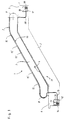
- FIG. 1 shows a schematic diagram of an escalator 1, the essential components of which are given as follows become: a scaffold 2, a balustrade 3, a merely indicated step belt 4, one in the scaffold 2 provided upper and lower maintenance room 5.6, the not shown for receiving Serves drive components and the like, and one on the top of the balustrade 3rd extending handrail 7, which can be deflected in the area of the balustrade heads 8.9.
- a scaffold 2 a balustrade 3
- a merely indicated step belt 4 one in the scaffold 2 provided upper and lower maintenance room 5.6, the not shown for receiving Serves drive components and the like
- the balustrade 3rd extending handrail 7 which can be deflected in the area of the balustrade heads 8.9.
- For lighting the balustrade 3 and the step belt 4 are two from each other in this example independent lighting devices 10, 11 are provided.
- independent lighting devices 10, 11 are provided.
- other variants are also conceivable, depending on the particular application are to be adjusted.
- the lighting device 10 includes a projector 12, the one contains active light source 13 in the form of a lamp and a mirror 14 as a lens.
- On off Glass fiber material existing light guide 15 is used, in which the bundled Light from the lamp 13 is fed in at its end 16 facing the lamp 13.
- Of the Light guide 15 has a predetermined thickness (e.g. 20 mm diameter) and is from the maintenance room 6 in a protected form in the area of the balustrade head 8. Because the light guide 15 has side light emission (i.e. light is emitted over its entire circumferential surface), it should be in the areas of the passenger conveyor that are not necessarily illuminated must be or where stray light to irritate the users of the passenger conveyor system 1 could result in a darkened form, e.g.
- Partial lengths of the light guide 15 are designated by the reference symbol 15 ′, e.g. may be necessary due to the modular design of the escalator 1, but not must be used.
- the lighting device 11 can be viewed analogously to this. It also consists of a projector 17 together with lamp 18 and lens 19. Light from this active light source 18 is transferred to another Optical fiber 20 fed, which in this example consist of a continuous strand should. Depending on the application, sections can of course also be used here. This light guide 20 is used to illuminate the step band 4.
- the design of the projector power depends on the desired brightness and the length of the passenger conveyor system, the length of an escalator, especially for escalators, is several times as long can exceed.
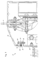
- FIG. 2 shows a cross section through the handrail guide, for example that shown in FIG. 1 Escalator 1.
- a handrail guide element 22 placed on the profile 21 and the Handrail 7 itself.
- the handrail guide element 22 is releasably attached to the profile 21, for example via screws 23 only indicated here.
- the profile 21 also has a in its longitudinal direction extending cavity 24 to receive the here also only indicated light guide 15 is used.
- a reflective film 26 may be provided.
- the profile 21 is placed in the middle of the balustrade 3 and preferably by gluing associated with this.
- Other configurations, in particular asymmetrical arrangements, are also conceivable depending on the type of passenger conveyor system desired.
- the light guide 15 the cavity when the film is not necessary 24 largely filled out.
- the feeding of the light into the Cross section of the light guide 15. comes from at least one lamp 13, 18 and at least a lens 14, 19 existing projector 12, 17 according to FIG. 1, which is preferably used is positioned in the maintenance room 5, 6 of the passenger conveyor system 1.
- FIG. 3 shows the base area 27 of the escalator 1 according to FIG. 1.
- the step belt can be seen 4, the skirting board 28 and the roof element 29, which is located between the skirting board 28 and the balustrade 3 extends.
- the skirting 28 is angled, the profile 30 being placed on the angled area 31.
- the profile 30 is fixed in the area of the skirting board 28.
- a continuous Cavity 34 is provided for receiving the light guide, which is also only indicated 20 serves.
- a reflective member 35 in the area Cavity 34 are provided.
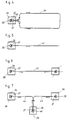
- FIGS. 4 to 7 show different types of feed options for active light Light guide.
- projectors 36 the lamps 37 as active light sources and lenses 38 for focusing the light into a concentrated light beam.
- the lamp 37 has a relatively high wattage so that it is able to emit light feed in a closed light guide circuit 39 in such a way that in both ends 40.41 equally light is fed, which then spreads in the direction of the arrow. So both the area of the balustrade and the area can be seen by only one projector 36 of the step or pallet belt are illuminated to the same extent.
- Figure 5 shows a single projector 36 for feeding light into a single light guide 42, for example for lighting the balustrade, the step or pallet belt or an ascent or descent of the passenger conveyor. In the latter case it could increase the safety here clocked light can be fed into the light guide 42.
- Figure 7 shows another alternative. Three projectors 36 are shown, which are connected to different Place 44.45 light at sections. This variant can also be too long Passenger conveyors are used. Likewise, there is the option of preferred Subareas, e.g. B. for warning purposes, clocked light in the respective sub-area 44 and / or feed 45. There is also the possibility, for example, in the area one of the projectors 36 has a rotatably drivable disc that produces optical effects 46 by means of which e.g. alternating colors can be generated.
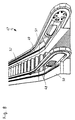
- FIG. 8 shows a further alternative to the arrangement of the lighting device according to the invention in the area of an escalator 47.
- the continuous light guides 48, 49 are in this Example provided in the base area 50, 51 outside of the step belt 52, whereby an essentially upward light emission can be achieved. Through this Measure can bring about a wide variety of effects in the manner already described above become.
- the light feed into the light guide 48, 49 can be analogous to that previously described Embodiments take place.
- To accommodate the light guide 48, 49 can be analogous to Figures 2 and 3 also use a profile not shown here.
Landscapes
- Escalators And Moving Walkways (AREA)
Description
- Figur 1 -
- Prinzipskizze einer Rolltreppe mit angedeuteter Beleuchtung sowohl der Balustrade als auch des Stufenbandes
- Figur 2 -
- Querschnitt durch die Handlaufführung der Personenförderanlage gemäß Figur 1
- Figur 3 -
- Darstellung des Sockelbereiches der Personenförderanlage gemäß Figur 1
- Figuren 4 bis 7 -
- Unterschiedliche Lichteinspeisungsmöglichkeiten in Lichtleiter für Personenförderanlagen
- Figur 8 -
- Alternative Anordnung einer Beleuchtungseinrichtung an einer Rolltreppe
Claims (24)
- Beleuchtungseinrichtung für Personenförderanlagen, wie Rolltreppen und Rollsteige, die insbesondere im Bereich des Handlaufes (7) und/oder des Sockels (27) der Personenförderanlage (1) vorgesehen ist, bestehend aus mindestens einem im wesentlichen in Transportrichtung der Personenförderanlage (1,47) verlaufenden, zumindest im Einbauzustand durchgehenden Lichtleiter (15,20,39,42,43,44,45,48,49) mit seitlichem Lichtaustritt, der im Bereich mindestens eines seiner Enden (16,40,41) von dem gebündelten Lichtstrahl mindestens einer Lichtquelle (13,18,37) beaufschlagbar ist.
- Beleuchtungseinrichtung nach Anspruch 1, dadurch gekennzeichnet, daß der Lichtleiter (15,20, 39,42-45,48,49) über seine Teillänge bzw. seine Länge gesehen aus einem homogenen durchscheinenden Material besteht.
- Beleuchtungseinrichtung nach den Ansprüchen 1 und 2, dadurch gekennzeichnet, daß der Lichtleiter (15,20,39,42-45,48,49) aus einem biegsamen Glasfaser- oder Kunststoffmaterial mit glatter Außenumfangsfläche besteht.
- Beleuchtungseinrichtung nach den Ansprüchen 1 bis 3, dadurch gekennzeichnet, daß der Lichtleiter (10,20,39,42-45,48,49) zumindest partiell innerhalb einer aus durchscheinendem Material bestehenden Schutzhülle geführt ist.
- Beleuchtungseinrichtung nach den Ansprüchen 1 bis 4, dadurch gekennzeichnet, daß der Lichtleiter (15,20) in einem Hohlraum (24,34) eines aus durchscheinendem Material bestehenden Profils (21,30) geführt ist.
- Beleuchtungseinrichtung nach den Ansprüchen 1 bis 5, dadurch gekennzeichnet, daß der Lichtleiter (15,20) den Querschnitt des Hohlraumes (24,34) im wesentlichen ausfüllt.
- Beleuchtungseinrichtung nach den Ansprüchen 1 bis 6, dadurch gekennzeichnet, daß der Lichtleiter (15,20) einen im wesentlichen gerundeten, insbesondere kreisrunden, Querschnitt aufweist.
- Beleuchtungseinrichtung nach den Ansprüchen 1 bis 7, dadurch gekennzeichnet, daß das Profil (21,30) aus einem Kunststoff, insbesondere aus Acryl, besteht.
- Beleuchtungseinrichtung nach den Ansprüchen 1 bis 8, dadurch gekennzeichnet, daß das Profil (21) zur Aufnahme des Handlaufes (7) einenends auf die korrespondierende Balustrade (1) aufgesteckt und andernends mit einem Handlaufführungselement (22) verbunden ist.
- Beleuchtungseinrichtung nach den Ansprüchen 1 bis 8, dadurch gekennzeichnet, daß das Profil (30) im Bereich einer Ausnehmung der Sockelleiste (28) vorgesehen und mit Bauteilen (31,32,33) derselben, insbesondere lösbar, verbunden ist.
- Beleuchtungseinrichtung nach den Ansprüchen 1 bis 10, dadurch gekennzeichnet, daß der Lichtleiter (15) im Bereich mindestens einer der Handlaufumlenkungen (8) unterhalb des Handlaufes (7) geführt ist.
- Beleuchtungseinrichtung nach den Ansprüchen 1 bis 11, dadurch gekennzeichnet, daß der Lichtleiter (15) im Bereich der Handlaufumlenkung (8) abgedunkelt geführt ist.
- Beleuchtungseinrichtung nach den Ansprüchen 1 bis 12, dadurch gekennzeichnet, daß der Lichtleiter (15) im Bereich der Umlenkung (8) innerhalb eines aus nicht durchscheinendem Material bestehenden Elementes, insbesondere eines Schlauches, geführt ist.
- Beleuchtungseinrichtung nach den Ansprüchen 1 bis 13, dadurch gekennzeichnet, daß zur Konzentration des aus dem Lichtleiter (15,20,39,42-45,48,49) auf seiner gesamten Umfangsfläche seitlich austretenden Lichtes im Bereich der nicht zur Beleuchtung erforderlichen Umfangsfläche der Hohlraum (24,34) und/oder der Lichtleiter (15,20) mit einem aus reflektierendem Bauteil, insbesondere einer Folie (26,35), versehen ist bzw. sind.
- Beleuchtungseinrichtung nach den Ansprüchen 1 bis 14, dadurch gekennzeichnet, daß die Lichtquelle in an sich bekannter Weise nach Art eines Projektors (12,17,36) ausgebildet ist, wobei die Bündelung des durch mindestens eine elektrische Lampe (13,18,37) erzeugten Lichtes durch mindestens eine Linse (14,19,38) herbeiführbar ist, die den gebündelten Lichtstrahl auf die stirnseitige Querschnittsfläche des Lichtleiters (15,20) projiziert.
- Beleuchtungseinrichtung nach den Ansprüchen 1 bis 15, dadurch gekennzeichnet, daß der Projektor (12,17,36) außerhalb des sichtbaren Bereiches der Personenförderanlage (1,47), insbesondere im Wartungsraum (5,6) derselben angeordnet ist.
- Beleuchtungseinrichtung nach den Ansprüchen 1 bis 16, dadurch gekennzeichnet, daß für jede Seite der Personenförderanlage (1,47) mindestens ein Projektor (12,17,36) vorgesehen ist.
- Beleuchtungseinrichtung nach den Ansprüchen 1 bis 17, dadurch gekennzeichnet, daß jeweils einer der Projektoren (12,17,36) für einen Lichtleiter (15,20,39,42-45) im Bereich des Handlaufes (7) und jeweils ein weiterer Projektor (12,17,36) für einen Lichtleiter (15,20,39,42-45) im Bereich der Sockelleiste (28) vorgesehen ist.
- Beleuchtungseinrichtung nach Anspruch 18, dadurch gekennzeichnet, daß einer der beiden Projektoren (12,17,36) zur Einspeisung eines kontinuierlichen und der andere Projektor (12,17,36) zur Einspeisung eines diskontinuierlichen Lichtsignals vorgesehen ist.
- Beleuchtungseinrichtung nach den Ansprüchen 1 bis 19, gekennzeichnet, durch mehrere, in Transportrichtung der Personenförderanlage (1,47) gesehen, an geschützten Bereichen derselben angeordnete Projektoren (12,17,36) zur Einspeisung ggf. unterschiedlicher Lichtsignale in korrespondierende Endbereiche der bzw. des Lichtleiter(s).
- Beleuchtungseinrichtung nach den Ansprüchen 1 bis 20, dadurch gekennzeichnet, daß zwischen der Lampe (13,18,37) und der Linse (14,19,38) optische Effekte hervorrufende Elemente (46) vorgesehen sind.
- Beleuchtungseinrichtung nach Anspruch 21, dadurch gekennzeichnet, daß die Elemente (46) scheibenförmig ausgebildet und relativ zur Linse (38) in Umfangsrichtung, insbesondere motorisch angetrieben, drehbar sind.
- Beleuchtungseinrichtung nach einem oder mehreren der Ansprüche 1 bis 22, dadurch gekennzeichnet, daß der Lichtleiter (48,49) im Sockelbereich (50,51) der Personenförderanlage (47) außerhalb des Stufenbandes (52) vorgesehen ist.
- Beleuchtungseinrichtung nach Anspruch 23, dadurch gekennzeichnet, daß der Lichtleiter (48,49) mit im wesentlichen nach oben gerichtetem Lichtaustritt im Sockelbereich (50,51) vorgesehen ist.
Applications Claiming Priority (5)
| Application Number | Priority Date | Filing Date | Title |
|---|---|---|---|
| DE19539307 | 1995-10-23 | ||
| DE19539307 | 1995-10-23 | ||
| DE19546937 | 1995-12-15 | ||
| DE19546937A DE19546937C2 (de) | 1995-10-23 | 1995-12-15 | Beleuchtungseinrichtung für Personenförderanlagen |
| PCT/EP1996/004527 WO1997015520A1 (de) | 1995-10-23 | 1996-10-18 | Beleuchtungseinrichtung für personenförderanlagen |
Publications (2)
| Publication Number | Publication Date |
|---|---|
| EP0857156A1 EP0857156A1 (de) | 1998-08-12 |
| EP0857156B1 true EP0857156B1 (de) | 1999-05-12 |
Family
ID=26019686
Family Applications (1)
| Application Number | Title | Priority Date | Filing Date |
|---|---|---|---|
| EP96934738A Expired - Lifetime EP0857156B1 (de) | 1995-10-23 | 1996-10-18 | Beleuchtungseinrichtung für personenförderanlagen |
Country Status (10)
| Country | Link |
|---|---|
| US (1) | US6129442A (de) |
| EP (1) | EP0857156B1 (de) |
| JP (1) | JPH11513649A (de) |
| CN (1) | CN1103314C (de) |
| AT (1) | ATE179956T1 (de) |
| BR (1) | BR9611240A (de) |
| CZ (1) | CZ123998A3 (de) |
| ES (1) | ES2131965T3 (de) |
| SK (1) | SK282464B6 (de) |
| WO (1) | WO1997015520A1 (de) |
Families Citing this family (28)
| Publication number | Priority date | Publication date | Assignee | Title |
|---|---|---|---|---|
| US6869202B2 (en) * | 1999-08-11 | 2005-03-22 | Brian N. Tufte | Lighting apparatus |
| US6883931B2 (en) * | 1999-08-11 | 2005-04-26 | Brian N. Tufte | Elongated illumination device |
| US6733161B2 (en) | 1999-08-11 | 2004-05-11 | Brian N. Tufte | Elongated carrier for bumper member |
| US6921184B2 (en) * | 1999-08-11 | 2005-07-26 | Brian N. Tufte | Elongated illumination device |
| US7401949B2 (en) * | 1999-08-11 | 2008-07-22 | I3 Ventures | Illuminated rub-rail/bumper assembly |
| US6837591B2 (en) * | 1999-08-11 | 2005-01-04 | Tufte Brian N | Kitchen appliance with elongated light source |
| US6817731B2 (en) * | 1999-08-11 | 2004-11-16 | Brian N. Tufte | Elongated illumination device |
| JP3769450B2 (ja) * | 2000-05-17 | 2006-04-26 | 株式会社日立製作所 | 乗客コンベア |
| JP2002087749A (ja) * | 2000-09-05 | 2002-03-27 | Otis Elevator Co | 帯状発光体付きエスカレータ |
| AU2001291546A1 (en) * | 2000-09-08 | 2002-03-22 | Ronald H. Ball | Illumination system for escalator handrails |
| US6725607B1 (en) * | 2001-09-08 | 2004-04-27 | Edward J. Flynn | Handrail safety device and method |
| JP3858219B2 (ja) * | 2001-10-25 | 2006-12-13 | ミネベア株式会社 | ブラシレス直流1相モータのプリドライブ回路 |
| US7575499B2 (en) * | 2001-11-16 | 2009-08-18 | 13 Ventures, Llc | Toy with elongated light source |
| USD596090S1 (en) | 2002-02-12 | 2009-07-14 | I3Ventures, LLC | Illuminated rub rail |
| ES2639837T3 (es) * | 2003-06-17 | 2017-10-30 | Inventio Ag | Sistema de iluminación para una escalera mecánica |
| JP4401138B2 (ja) * | 2003-10-10 | 2010-01-20 | 東芝エレベータ株式会社 | 乗客コンベア |
| US7134773B2 (en) * | 2004-03-29 | 2006-11-14 | I3 Ventures, Llc | Lighting apparatus |
| ATE430110T1 (de) * | 2004-11-26 | 2009-05-15 | Otis Elevator Co | Glasbrüstungsbeleuchtung für personenförderanlage |
| US20060201293A1 (en) * | 2005-03-14 | 2006-09-14 | Tufte Brian N | Lighting apparatus |
| US20090175031A1 (en) * | 2006-05-19 | 2009-07-09 | Dirk Winkelhake | People conveyor lighting |
| US20080007418A1 (en) * | 2006-06-26 | 2008-01-10 | Maki Brian E | Proximity-triggered handrail cueing system with automatic attention capture |
| CN101210658B (zh) * | 2006-12-29 | 2011-05-25 | 通力股份公司 | 人员传送装置的照明系统 |
| WO2009141225A1 (de) * | 2008-05-21 | 2009-11-26 | Inventio Ag | Handlauf für eine fahrtreppe oder einen fahrsteig |
| US8286782B2 (en) * | 2008-11-17 | 2012-10-16 | Industrial Technology Research Institute | Information display system for passenger conveying device |
| CN102363483A (zh) * | 2011-06-29 | 2012-02-29 | 苏州新达电扶梯部件有限公司 | 一种电梯护栏斜挡板 |
| JP6208571B2 (ja) * | 2013-12-18 | 2017-10-04 | 株式会社日立製作所 | 乗客コンベア |
| JP6958976B2 (ja) * | 2019-11-29 | 2021-11-02 | 東芝エレベータ株式会社 | 乗客コンベア |
| JP7224517B1 (ja) * | 2022-06-13 | 2023-02-17 | 三菱電機株式会社 | 乗客コンベアの欄干装置 |
Family Cites Families (11)
| Publication number | Priority date | Publication date | Assignee | Title |
|---|---|---|---|---|
| US2479500A (en) * | 1946-08-26 | 1949-08-16 | Harry E Longberg | Illuminating means |
| US4733332A (en) * | 1985-02-22 | 1988-03-22 | Agency Of Industrial Science And Technology | Illuminating device |
| DE3528177A1 (de) * | 1985-08-06 | 1987-02-19 | Lp Plast Ges Zur Verarbeitung | Leuchte unter verwendung von lichtleitmaterialien |
| US4800474A (en) * | 1986-05-15 | 1989-01-24 | Vari-Lite, Inc. | Color wheel assembly for lighting equipment |
| DE3804732C2 (de) * | 1988-02-15 | 1993-10-14 | Oka Kano & Oehmichen Kg Forsch | Verfahren zum Herstellen eines Reflektors |
| DE8802483U1 (de) * | 1988-02-25 | 1988-04-07 | Thyssen-M.A.N. Aufzüge GmbH, 2000 Hamburg | Fahrtreppe oder Fahrsteig |
| JPH0747459B2 (ja) * | 1988-11-09 | 1995-05-24 | 株式会社日立製作所 | 乗客コンベアの表示装置及びそれに用いる表示体並びに表示装置の組立方法 |
| US4896759A (en) * | 1989-04-12 | 1990-01-30 | Otis Elevator Company | Handrail mount deflector for streamlined escalator newels |
| CA2017824A1 (en) * | 1989-07-14 | 1991-01-14 | Gerhart Ruelke | Illuminating equipment for the illumination of escalators or travelling walkways |
| US5339228A (en) * | 1993-10-13 | 1994-08-16 | Otis Elevator Company | Escalator or moving walkway balustrade illumination |
| ATE180463T1 (de) * | 1994-03-09 | 1999-06-15 | Inventio Ag | Beleuchtungsvorrichtung mit lichtleitern für fahrtreppen oder fahrsteige |
-
1996
- 1996-10-18 JP JP9516255A patent/JPH11513649A/ja active Pending
- 1996-10-18 EP EP96934738A patent/EP0857156B1/de not_active Expired - Lifetime
- 1996-10-18 BR BR9611240A patent/BR9611240A/pt not_active Application Discontinuation
- 1996-10-18 SK SK480-98A patent/SK282464B6/sk unknown
- 1996-10-18 AT AT96934738T patent/ATE179956T1/de not_active IP Right Cessation
- 1996-10-18 ES ES96934738T patent/ES2131965T3/es not_active Expired - Lifetime
- 1996-10-18 CN CN96197798A patent/CN1103314C/zh not_active Expired - Fee Related
- 1996-10-18 US US09/051,850 patent/US6129442A/en not_active Expired - Fee Related
- 1996-10-18 CZ CZ981239A patent/CZ123998A3/cs unknown
- 1996-10-18 WO PCT/EP1996/004527 patent/WO1997015520A1/de not_active Ceased
Also Published As
| Publication number | Publication date |
|---|---|
| SK282464B6 (sk) | 2002-02-05 |
| BR9611240A (pt) | 1999-03-30 |
| CN1103314C (zh) | 2003-03-19 |
| EP0857156A1 (de) | 1998-08-12 |
| WO1997015520A1 (de) | 1997-05-01 |
| ATE179956T1 (de) | 1999-05-15 |
| US6129442A (en) | 2000-10-10 |
| CZ123998A3 (cs) | 1999-02-17 |
| ES2131965T3 (es) | 1999-08-01 |
| JPH11513649A (ja) | 1999-11-24 |
| SK48098A3 (en) | 1998-11-04 |
| CN1200099A (zh) | 1998-11-25 |
Similar Documents
| Publication | Publication Date | Title |
|---|---|---|
| EP0857156A1 (de) | Beleuchtungseinrichtung für personenförderanlagen | |
| DE20114561U1 (de) | Scheibenleuchte | |
| EP1205352A2 (de) | Beleuchtungseinrichtung | |
| EP0676362B1 (de) | Beleuchtungsvorrichtung mit Lichtleitern für Fahrtreppen oder Fahrsteige | |
| EP1106913A1 (de) | Leiterplattenmontierbares Anzeigeelement | |
| DE4227468C2 (de) | Elektrische Schaltereinheit, insbesondere zur Steuerung von Klimaanlagen in Kraftfahrzeugen | |
| DE20019698U1 (de) | Fahrtreppe oder Fahrsteig | |
| DE8802483U1 (de) | Fahrtreppe oder Fahrsteig | |
| DE19546937C2 (de) | Beleuchtungseinrichtung für Personenförderanlagen | |
| DE19957680A1 (de) | Beleuchtungseinrichtung für Personenförderanlagen | |
| DE19962040A1 (de) | Lichtleiterplatte mit einer Randkante und aufgebrachten und von der Betrachterseite wahrnehmbaren Zeichen | |
| DE29519919U1 (de) | Beleuchtungseinrichtung für Personenförderanlagen | |
| DE4209505C1 (en) | Safe lighting system for indoor and outdoor escalators - employs optical fibre assembly and single light-source to illuminate escalator steps without need for electrical wiring and weatherseals | |
| DE10036812A1 (de) | Beleuchtungseinrichtung | |
| DE19748636A1 (de) | Lichtwellenleiter, insbesondere zur induvidialisierenden Anwendung | |
| EP1122487A2 (de) | Bauelemente mit Lichtübertragungsmedium | |
| DE10112640C1 (de) | Anzeigeeinrichtung | |
| DE9203944U1 (de) | Rolltreppe | |
| EP0931976B1 (de) | Anordnung zum gleichmässigen Be- bzw. Ausleuchten einer Fläche zum Anzeigen von Informationen | |
| EP0888996A1 (de) | Sicherheitseinrichtung für eine Personenfördereinrichtung | |
| DE19838497A1 (de) | Leuchteinrichtung mit Lichtquellen, die als Lumineszensdioden ausgebildet sind | |
| WO2007128448A1 (de) | Sanitäre handbrause | |
| DE102023106300A1 (de) | Fahrwegvorrichtung mit sich seitlich des Fahrwegs erstreckendem Sockel | |
| EP1657209A1 (de) | Fahrtreppe oder Fahrsteig | |
| EP1065165A2 (de) | Beleuchtung von Fahrtreppen oder Fahrsteigen |
Legal Events
| Date | Code | Title | Description |
|---|---|---|---|
| PUAI | Public reference made under article 153(3) epc to a published international application that has entered the european phase |
Free format text: ORIGINAL CODE: 0009012 |
|
| 17P | Request for examination filed |
Effective date: 19980401 |
|
| AK | Designated contracting states |
Kind code of ref document: A1 Designated state(s): AT BE CH DE ES FR GB IT LI NL SE |
|
| GRAG | Despatch of communication of intention to grant |
Free format text: ORIGINAL CODE: EPIDOS AGRA |
|
| GRAG | Despatch of communication of intention to grant |
Free format text: ORIGINAL CODE: EPIDOS AGRA |
|
| GRAH | Despatch of communication of intention to grant a patent |
Free format text: ORIGINAL CODE: EPIDOS IGRA |
|
| 17Q | First examination report despatched |
Effective date: 19980928 |
|
| GRAH | Despatch of communication of intention to grant a patent |
Free format text: ORIGINAL CODE: EPIDOS IGRA |
|
| GRAA | (expected) grant |
Free format text: ORIGINAL CODE: 0009210 |
|
| AK | Designated contracting states |
Kind code of ref document: B1 Designated state(s): AT BE CH DE ES FR GB IT LI NL SE |
|
| REF | Corresponds to: |
Ref document number: 179956 Country of ref document: AT Date of ref document: 19990515 Kind code of ref document: T |
|
| REG | Reference to a national code |
Ref country code: CH Ref legal event code: NV Representative=s name: DIPL.-ING. ETH H. R. WERFFELI PATENTANWALT Ref country code: CH Ref legal event code: EP |
|
| GBT | Gb: translation of ep patent filed (gb section 77(6)(a)/1977) |
Effective date: 19990514 |
|
| REF | Corresponds to: |
Ref document number: 59601904 Country of ref document: DE Date of ref document: 19990617 |
|
| ET | Fr: translation filed | ||
| REG | Reference to a national code |
Ref country code: ES Ref legal event code: FG2A Ref document number: 2131965 Country of ref document: ES Kind code of ref document: T3 |
|
| PGFP | Annual fee paid to national office [announced via postgrant information from national office to epo] |
Ref country code: AT Payment date: 19990914 Year of fee payment: 4 |
|
| PGFP | Annual fee paid to national office [announced via postgrant information from national office to epo] |
Ref country code: SE Payment date: 19990920 Year of fee payment: 4 |
|
| PGFP | Annual fee paid to national office [announced via postgrant information from national office to epo] |
Ref country code: BE Payment date: 19991004 Year of fee payment: 4 |
|
| PGFP | Annual fee paid to national office [announced via postgrant information from national office to epo] |
Ref country code: ES Payment date: 19991006 Year of fee payment: 4 |
|
| RAP2 | Party data changed (patent owner data changed or rights of a patent transferred) |
Owner name: KONE CORPORATION |
|
| PLBE | No opposition filed within time limit |
Free format text: ORIGINAL CODE: 0009261 |
|
| STAA | Information on the status of an ep patent application or granted ep patent |
Free format text: STATUS: NO OPPOSITION FILED WITHIN TIME LIMIT |
|
| 26N | No opposition filed | ||
| NLT2 | Nl: modifications (of names), taken from the european patent patent bulletin |
Owner name: KONE CORPORATION |
|
| REG | Reference to a national code |
Ref country code: GB Ref legal event code: 732E |
|
| REG | Reference to a national code |
Ref country code: FR Ref legal event code: TP |
|
| PG25 | Lapsed in a contracting state [announced via postgrant information from national office to epo] |
Ref country code: AT Free format text: LAPSE BECAUSE OF NON-PAYMENT OF DUE FEES Effective date: 20001018 |
|
| PG25 | Lapsed in a contracting state [announced via postgrant information from national office to epo] |
Ref country code: ES Free format text: LAPSE BECAUSE OF NON-PAYMENT OF DUE FEES Effective date: 20001019 |
|
| PG25 | Lapsed in a contracting state [announced via postgrant information from national office to epo] |
Ref country code: SE Free format text: THE PATENT HAS BEEN ANNULLED BY A DECISION OF A NATIONAL AUTHORITY Effective date: 20001030 |
|
| PG25 | Lapsed in a contracting state [announced via postgrant information from national office to epo] |
Ref country code: LI Free format text: LAPSE BECAUSE OF NON-PAYMENT OF DUE FEES Effective date: 20001031 Ref country code: CH Free format text: LAPSE BECAUSE OF NON-PAYMENT OF DUE FEES Effective date: 20001031 Ref country code: BE Free format text: LAPSE BECAUSE OF NON-PAYMENT OF DUE FEES Effective date: 20001031 |
|
| BERE | Be: lapsed |
Owner name: O & K ROLLTREPPEN G.M.B.H. & CO. K.G. Effective date: 20001031 |
|
| PG25 | Lapsed in a contracting state [announced via postgrant information from national office to epo] |
Ref country code: NL Free format text: LAPSE BECAUSE OF NON-PAYMENT OF DUE FEES Effective date: 20010501 |
|
| REG | Reference to a national code |
Ref country code: CH Ref legal event code: PL |
|
| EUG | Se: european patent has lapsed |
Ref document number: 96934738.4 |
|
| NLV4 | Nl: lapsed or anulled due to non-payment of the annual fee |
Effective date: 20010501 |
|
| REG | Reference to a national code |
Ref country code: GB Ref legal event code: IF02 |
|
| REG | Reference to a national code |
Ref country code: ES Ref legal event code: FD2A Effective date: 20011113 |
|
| PGFP | Annual fee paid to national office [announced via postgrant information from national office to epo] |
Ref country code: FR Payment date: 20040913 Year of fee payment: 9 |
|
| PGFP | Annual fee paid to national office [announced via postgrant information from national office to epo] |
Ref country code: GB Payment date: 20040916 Year of fee payment: 9 |
|
| PG25 | Lapsed in a contracting state [announced via postgrant information from national office to epo] |
Ref country code: IT Free format text: LAPSE BECAUSE OF NON-PAYMENT OF DUE FEES;WARNING: LAPSES OF ITALIAN PATENTS WITH EFFECTIVE DATE BEFORE 2007 MAY HAVE OCCURRED AT ANY TIME BEFORE 2007. THE CORRECT EFFECTIVE DATE MAY BE DIFFERENT FROM THE ONE RECORDED. Effective date: 20051018 Ref country code: GB Free format text: LAPSE BECAUSE OF NON-PAYMENT OF DUE FEES Effective date: 20051018 |
|
| GBPC | Gb: european patent ceased through non-payment of renewal fee |
Effective date: 20051018 |
|
| PG25 | Lapsed in a contracting state [announced via postgrant information from national office to epo] |
Ref country code: FR Free format text: LAPSE BECAUSE OF NON-PAYMENT OF DUE FEES Effective date: 20060630 |
|
| REG | Reference to a national code |
Ref country code: FR Ref legal event code: ST Effective date: 20060630 |
|
| PGFP | Annual fee paid to national office [announced via postgrant information from national office to epo] |
Ref country code: DE Payment date: 20070921 Year of fee payment: 12 |
|
| PG25 | Lapsed in a contracting state [announced via postgrant information from national office to epo] |
Ref country code: DE Free format text: LAPSE BECAUSE OF NON-PAYMENT OF DUE FEES Effective date: 20090501 |