EP0856074B1 - Dispositif de livraison du fil - Google Patents
Dispositif de livraison du fil Download PDFInfo
- Publication number
- EP0856074B1 EP0856074B1 EP96934622A EP96934622A EP0856074B1 EP 0856074 B1 EP0856074 B1 EP 0856074B1 EP 96934622 A EP96934622 A EP 96934622A EP 96934622 A EP96934622 A EP 96934622A EP 0856074 B1 EP0856074 B1 EP 0856074B1
- Authority
- EP
- European Patent Office
- Prior art keywords
- detent member
- braking
- yarn feeder
- ring
- motor shaft
- Prior art date
- Legal status (The legal status is an assumption and is not a legal conclusion. Google has not performed a legal analysis and makes no representation as to the accuracy of the status listed.)
- Expired - Lifetime
Links
- 230000002093 peripheral effect Effects 0.000 claims description 17
- 230000000903 blocking effect Effects 0.000 claims description 10
- 239000004033 plastic Substances 0.000 claims description 6
- 229920003023 plastic Polymers 0.000 claims description 6
- 229920001971 elastomer Polymers 0.000 claims description 4
- 239000000806 elastomer Substances 0.000 claims description 2
- 238000009940 knitting Methods 0.000 claims description 2
- 239000011149 active material Substances 0.000 claims 2
- 230000000284 resting effect Effects 0.000 claims 1
- 238000004804 winding Methods 0.000 claims 1
- 230000000694 effects Effects 0.000 description 6
- 239000011324 bead Substances 0.000 description 3
- 239000000463 material Substances 0.000 description 3
- 230000001133 acceleration Effects 0.000 description 2
- 229910000831 Steel Inorganic materials 0.000 description 1
- 230000002411 adverse Effects 0.000 description 1
- 230000005284 excitation Effects 0.000 description 1
- 230000002349 favourable effect Effects 0.000 description 1
- 230000005484 gravity Effects 0.000 description 1
- 238000002347 injection Methods 0.000 description 1
- 239000007924 injection Substances 0.000 description 1
- 239000002184 metal Substances 0.000 description 1
- 238000013021 overheating Methods 0.000 description 1
- 230000000630 rising effect Effects 0.000 description 1
- 239000010959 steel Substances 0.000 description 1
Images

Classifications
-
- D—TEXTILES; PAPER
- D04—BRAIDING; LACE-MAKING; KNITTING; TRIMMINGS; NON-WOVEN FABRICS
- D04B—KNITTING
- D04B15/00—Details of, or auxiliary devices incorporated in, weft knitting machines, restricted to machines of this kind
- D04B15/38—Devices for supplying, feeding, or guiding threads to needles
- D04B15/48—Thread-feeding devices
- D04B15/482—Thread-feeding devices comprising a rotatable or stationary intermediate storage drum from which the thread is axially and intermittently pulled off; Devices which can be switched between positive feed and intermittent feed
-
- D—TEXTILES; PAPER
- D04—BRAIDING; LACE-MAKING; KNITTING; TRIMMINGS; NON-WOVEN FABRICS
- D04B—KNITTING
- D04B15/00—Details of, or auxiliary devices incorporated in, weft knitting machines, restricted to machines of this kind
- D04B15/38—Devices for supplying, feeding, or guiding threads to needles
- D04B15/48—Thread-feeding devices
Definitions
- the invention relates to a thread delivery device in the preamble of claim 1 specified Art.
- a return movement of the storage drum can be several Have causes.
- One in the feed area of the thread delivery device The provided thread scanner is spring-loaded and can after stopping the storage drum pull back the incoming thread and turn the storage drum back with the thread.
- the threads to be processed are mostly elastic, so that when stopping the storage drum the previously in tapered thread generated tension over the storage drum want to turn the thread back.
- less favorable Circumstances and due to a slowdown of the motor create a counter torque that the storage drum want to turn back.
- the well-known backstop is technically complex, prone to wear and tear can especially when accelerating or at higher speeds cause unwanted vibrations, among other things because the disc has an extremely large diameter and works with a very large lever arm.
- the well-known backstop requires an almost exactly vertical arrangement of the thread delivery device, like they don't in some use cases is observable. Furthermore, structurally complex measures are required to burn the disc at its top To prevent the top wall of the motor contacting end face because the disc covers the top wall at a great distance from the Axis of rotation touches and therefore at high speed considerable friction is to be destroyed ..
- the invention has for its object a yarn delivery device of the type mentioned at the beginning, in which a structural simple, easy-to-assemble backstop provided is reliable, wear-resistant with a long service life works and does not cause vibrations.
- the braking surface can be set to a diameter which can be significantly smaller than the inside diameter of one if applicable, provided storage drum. Shows the rotating element the tendency to move backwards, then it will Locking element relative to the abutment in a smooth-running Rotational movement twisted by the drag force until its counter braking range thanks to the eccentric to the axis of rotation of the rotating element Circle outwards or inwards against the braking surface starts and blocks the return movement.
- the engagement in the blocking position takes place harmoniously and reliably, whereby a high braking power can be generated.
- a high braking power can be generated.
- the locking member when restarting the rotary element easily and forcibly in the correct direction of rotation detaches from the braking surface and returns to the defined one Run position returns.
- the area of engagement between the Locking element and the braking surface can be designed over a large area, so that no excitation to vibrations in the thread delivery device arises.
- the backstop works reliably and with little wear with a long service life.
- the characteristic curve can be predetermined precisely and can be optimally designed with which the backstop takes effect comes or is solved again.
- the backstop is optimal on one made small diameter, and in particular on a Diameter independent of the size of the storage drum.
- the towing force can be exactly according to claim 3 Predetermine the dimension of the spring force. Conveniently it is pressed against the effect of gravity.
- the thread delivery device can therefore be installed in any position use without endangering the backstop. Further can be the area in which the locking member the towing surface contacted, relatively close to the axis of rotation of the rotating element set so that even at high speeds and strong accelerations the risk of burning the Blocking member is avoided, also by the ring shape, the one relatively low specific surface pressure per unit area enables and yet the sufficient towing force guaranteed.
- the embodiment according to claim is particularly expedient 5, where the motor is fixed in the housing and the backstop well encapsulated from the working area of the storage drum is separated, in which dirt and lint are inevitable are. Since the locking member does not work with the Has inside diameter of the storage drum, the Select the diameter of the braking surface small enough to be high Speeds and strong accelerations in modern Thread delivery devices to rule out vibrations.
- the motor shaft over the co-rotating Backstop supported on the housing against a return.
- the backstop makes according to claim 7 Rotary movement of the rotating element does not co-operate, but acts first with a return to the motor shaft over the for example block the braking surface attached to the motor shaft.
- the locking member works with a brake ring together who among other things provides a high braking effect due to the material.
- a brake ring could be placed directly on or in the Locking member can be attached (claim 9).
- a good backstop is also according to claim 10 reached a braking surface that is only structured, for example is knurled.
- This braking surface can be in a metallic Body arranged, for example in the housing or in a housing insert.
- Plastic molded parts are characterized by high Shape accuracy, low weight and low wear out. Because the locking member by precisely adjustable spring force the towing surface is pressed, self-lubricating Plastic grades are used, which is a smooth Ensure rotatability of the locking element even over a long service life.
- the self-lubricating effect has a braking effect with the braking surface no adverse influence because there by the eccentric movement of the locking member a quick-acting forced intervention can be produced anyway.
- the embodiment according to claim 12 is structurally simple and ensures low-wear work even over long periods Service life.
- the projections or the circumferential bead are one Assembly aid for a pre-mintable unit because the The washer does not come off the ring flange under the force of the spring can fall off.
- the ring disk comes into operation normally not to the protrusions or to the peripheral bead.
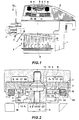
- a thread delivery device F preferably a thread delivery device F for a knitting machine, has a stationary housing G, on the underside of a storage drum T rotatably mounted which is about an axis of rotation X by means of a motor M in a predetermined direction of rotation to be driven.
- the Motor M can be switched on and off by means of signals, that of a scanning device D in a housing bracket 1 depending on the size of one on the storage drum T formed thread supply (not shown) are generated.
- the fed to the storage drum T by a not shown Supply spool coming thread (not shown) is through stationary Thread eyelets 2 passed and passed through a thread brake 3 under surveillance by a sensing element 5 to the extent the storage drum T.
- An inclined feed element V pushes each turn wound on the storage drum T. in Fig. 1 down, so that a thread supply of several Turns is formed.
- the thread intended for consumption is pulled off over the top of the storage drum.
- a backstop R is provided in the thread delivery device F, namely between an upper cover wall 6 of the housing G and the upper end of a motor shaft H.
- the backstop R contains in the embodiment of Fig. 1 with the motor shaft H rotatably connected abutment W and a relative to it rotatably supported by a weak coil spring 4 upward loaded blocking element S, which is used for cooperation provided with a braking surface B in the top wall 6 Insert 7 is used, namely a return or a Return movement of the storage drum T or the motor shaft H prevent after a standstill.
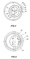
- the abutment W is an annular body A1 from a hub 8, which has a non-circular inner bore 9 attached to the matching end 10 of the motor shaft H in a rotationally fixed manner is a radial flange 11, which is a spring seat 12 defined, and an axial ring flange 14 with a cylindrical Outer peripheral surface 15, whose axis is opposite to X1 the axis of rotation X of the motor shaft H is eccentric. Further is in the annular flange 14 a cutout limited in the circumferential direction 17 molded, the (Fig. 3) two in the circumferential direction spaced stops 18 and 18 'defined. In the end area a circumferential bead 16 is formed on the ring flange 14.
- Locking member S that which is mounted on the abutment W relatively rotatably to this Locking member S is also an annular body A2, namely an annular disc 19 with an inner bore 20 and one cylindrical outer circumference 21, which is used for cooperation with the Braking area B is determined.
- the central axis of the peripheral surface 21 is correct in the running position of the backstop R with the axis of rotation X at least approximately.
- the annular disc 19 In one face the annular disc 19 is concentric with the peripheral surface 21 Spring receiving groove 13 formed for the coil spring 4, the other end in the spring seat 12 of the Flange 11 supports and the annular disc 19 with at least a part 22 of its other end face against a housing-fixed Drag surface 23 presses.
- a nose 26 In the inner bore 20 the annular disc 19 a nose 26 protrudes inwards, 4 stops 27 and 27 'defined with the Stops 18 and 18 'for setting a running position and cooperate in a locked position.
- the braking surface B and the Trailing surface 23 are included in the insert 7, which in the Cover wall 6 is set. It is conceivable the tow surface 23 and to arrange the braking surface 21 directly in the top wall 6.
- the braking surface B is on one Brake ring 24 made of a frictional material, such as rubber, elastomer or another plastic, provided in a Version 25 of insert 7 is set.
- a radial Game Y provided in the in Fig. 2 shown running position, in which the backstop R the normal rotation of the motor shaft H is not affected the peripheral surface 21 and the braking surface B a radial Game Y provided.
- the two ring bodies A1, A2 are expediently plastic parts, for example injection molded parts.
- the insert 7 can consist of metal, for example steel.
- the braking surface B could also be directly from the inner peripheral surface of the socket 25 are formed, which then expediently a roughened Surface structure, for example knurling, has.
- the peripheral surface 21 could, if necessary, be structured to increase the frictional engagement.
- the locking member S sits in accordance with FIG the rotational position shown in FIG. 4 on the ring flange 14 of the abutment W, which is in the rotational position shown in Fig. 3 located.
- the nose 26 is at the stop 27 ' Stop 18 'on.
- the peripheral surface 21 is then essentially concentric to the axis of rotation X and is the braking surface B (Fig. 2) with the radial play Y opposite. 3 and 4 counterclockwise motor shaft H takes the locking member S over the abutment w without it the braking surface B comes into contact. Because of the pressure the spring 8 becomes the locking member S against the drag surface 23 pressed so that a permanent Towing force in the locking element S acts in a clockwise direction stops with the stop 27 'at the stop 18'.
- a kinematic reversal is conceivable in such a way that the Ring body A2 on the top wall 6 or in the insert 7 rotatably is mounted, however, the ring body A1, the motor shaft H or the end 10 (which then has a cylindrical outer circumference has) rotatably comprises, expediently again with a radial play.
- the end surface 23 'then serves as the drag surface.
- the motor shaft H with the end face 22 'of the ring body A1 works together under the pressure of spring 4.
- the braking surface B can then either on the outer circumference of the motor shaft H or also provided in the inner bore 9 of the ring body A1 his.
- the ring body A2 forms the abutment W and the ring body A1 the locking member S.
- FIGS. 2, 3 and 4 are the embodiment shown in FIGS. 2, 3 and 4 schematically shown, in which the locking member S on the outside the abutment W is rotatably mounted and with the braking surface B works together.
- Fig. 6 the kinematic reversal is indicated, in which the abutment W arranged outside on the locking member S and (indicated by crosses) is rotatably held.
- the locking link S is rotatable relative to the motor shaft H.
- the blocking effect is between the inner bore 9 and the braking surface B or brought about the outer circumference of the motor shaft H.
- the schematic of the 5 is on the outer circumference 21st the locking member S is a limited braking surface area in the circumferential direction 21 'preformed, the to cooperation with the braking surface B is determined.
- the abutment W is here Ring body with a non-circular outer circumference, which is the definition of the Abutment simplified. 7 and 8, the braking surface area 21 'and 9' also have a curvature, the Center of curvature not with the center of the cylinder surface 21 or 9 coincides, i.e. the braking surface area 21 ' or 9 'could be curved more or less by one to achieve special braking effect.
- the backstop shown in Fig. 1 could also be below of the motor M may be arranged.
- the Backstop R however encapsulated and out of the influence of Soiling or fluff when processing thread material are inevitable, be separated.
- the diameter, on which the locking member interacts with the braking surface B, is advantageously much smaller than the diameter the storage drum T or its inner diameter.
- the size the contact area between the locking member and the Drag surface 23 or 23 ' should be chosen so that under the pressure of the spring 8 just sufficient for the function Tractive force guaranteed, however, overheating or a burning of the locking member is excluded.
Landscapes
- Engineering & Computer Science (AREA)
- Textile Engineering (AREA)
- Connection Of Motors, Electrical Generators, Mechanical Devices, And The Like (AREA)
- Knitting Machines (AREA)
- Forwarding And Storing Of Filamentary Material (AREA)
- Tension Adjustment In Filamentary Materials (AREA)
- Braking Arrangements (AREA)
Claims (13)
- Appareil fournisseur de fil (F), notamment pour machines à tricoter, comprenant un boítier fixe (G) et un élément tournant (T) qui tourillonne dans le boítier, et peut être entraíné dans un sens de rotation au moyen d'un moteur (M) pouvant être mis en circuit et hors circuit, et qui est destiné à enrouler un fil dans une réserve de fil composée de plusieurs spires sur une surface d'un accumulateur, d'où le fil peut être dévidé à la défilée en fonction de sa consommation, et comprenant un dispositif capteur qui détecte des déplacements de la limite de la réserve de fil qui varie dans la direction de l'extraction et au moyen duquel peuvent être produits des signaux pour la mise en circuit et hors circuit du moteur, et un arrêt anti-inversion mécanique qui interdit le mouvenent inverse de l'élément tournant et qui comprend un organe d'arrêt (S), lequel peut se déplacer par rapport à une contre-butée (W), entre une position de marche définie par une butée et une position d'arrêt, et peut être mis en appui contre une surface de frein, dans la position d'arrêt, et, lors du mouvement de rotation de l'élément tournant dans chaque sens de rotation, cet organe peut être amené avec une force d'entraínement produite par un contact de frottement et par la force d'entraínement, en fonction du sens de rotation, soit dans la position de marche, soit dans la position d'arrêt par rapport à la contre-butée, caractérisé en ce que la contre-butée (W) et l'organe d'arrêt (S) sont deux corps annulaires emboítés l'un dans l'autre et qui peuvent tourner l'un par rapport à l'autre autour de l'axe de rotation (X) de l'élément tournant (T) et dont la région de prise mutuelle est au moins un segment d'un cercle excentré par rapport à l'axe de rotation de l'élément tournant, et en ce que l'organe d'arrêt (S) qui coopère avec la surface de frein (B) présente sur sa circonférence (21) une région de frein (21') limitée dans la direction circonférentielle.
- Appareil fournisseur de fil selon la revendication 1, caractérisé en ce que le diamètre de la surface de frein (B) est nettement plus petit que le diamètre intérieur du tambour accumulateur (T).
- Appareil fournisseur de fil selon la revendication 1, caractérisé en ce qu'une surface frontale du corps annulaire (A1 ou A2) qui définit l'organe d'arrêt (S) peut être pressée, par une force élastique (4), à peu près parallèlement à l'axe de rotation (X) de l'élément tournant, contre une surface d'entraínement (23, 23') solidaire du boítier ou solidaire de l'élément tournant.
- Appareil fournisseur de fil selon la revendication 1, caractérisé en ce que, en supplément de la butée définissant la position de marche, il est aussi prévu une butée définissant une position d'arrêt, de préférence une position de fin d'arrêt, pour le mouvement relatif entre les corps annulaires.
- Appareil fournisseur de fil selon une des revendications 1 à 4, caractérisé en ce que l'élément tournant est un arbre (H) du moteur (M) agencé dans le boítier (G), qui porte solidairement en rotation un tambour accumulateur (T) et en ce que l'arrêt anti-inversion (R) est disposé entre une paroi (6) du boítier qui est éloignée du tambour accumulateur (T) et le moteur (M), et de préférence sur un prolongement (10) de l'arbre du moteur.
- Appareil fournisseur de fil selon la revendication 5, caractérisé en ce que le corps annulaire (A1) qui définit la contre-butée (W) est monté solidairement en rotation sur l'arbre (H) du moteur, en ce que le corps annulaire (A2) qui définit l'organe d'arrêt (S) est monté extérieurement sur le corps annulaire constituant la contre-butée, et en ce que la surface de frein (B) est disposée en dehors de l'organe d'arrêt (S) et que la surface d'entraínement (23) est disposée dans la paroi (6) du boítier et dirigée vers une surface frontale de l'organe d'arrêt (S), de préférence dans une pièce rapportée (7) tenue dans la paroi (6) du boítier.
- Appareil fournisseur de fil selon la revendication 5, caractérisé en ce que le corps annulaire (A1) qui définit la contre-butée est tenu immobilisé en rotation dans la paroi (6) du boítier, de préférence dans une portée de la paroi (6) du boítier, en ce que le corps annulaire (A2) qui définit l'organe d'arrêt (S) est tourillonné intérieurement dans le corps annulaire de la contre-butée, et en ce que la surface de frein (B), à l'intérieur de l'organe d'arrêt (S), et la surface d'entraínement (23'), dirigée vers une surface frontale de l'organe d'arrêt (S), sont agencées toutes deux sur l'arbre (H) du moteur, de préférence dans une pièce rapportée montée sur l'arbre (H) du moteur.
- Appareil fournisseur de fil selon la revendication 6 ou 7, caractérisé en ce que la surface de frein (B) est constituée par un anneau de frein (24) qui entoure l'organe d'arrêt (S) ou qui est entouré par l'organe d'arrêt (S), de préférence, avec un jeu radial (Y) dans la position de marche, et est faite d'une matière de friction, par exemple de caoutchouc ou d'un élastomère.
- Appareil fournisseur de fil selon au moins une des revendications 1 à 7, caractérisé en ce qu'un anneau de frein (24) fait d'une matière active de friction est disposé extérieurement sur, ou intérieurement dans, l'organe d'arrêt (S).
- Appareil fournisseur de fil selon au moins une des revendications 1 à 7, caractérisé en ce que la surface de frein (24, 25) est structurée, par exemple moletée.
- Appareil fournisseur de fil selon au moins une des revendications 1 à 10, caractérisé en ce que les deux corps annulaires (A1, A2) sont des pièces moulées en matière plastiques.
- Appareil fournisseur de fil selon les revendications 5 et 6, caractérisé en ce que le corps annulaire de la contre-butée est un moyeu (8) qui peut être monté solidairement en rotation sur l'arbre (H) du moteur, de préférence au moyen d'un perçage intérieur non circulaire (9), qui possède une collerette axiale annulaire (14) possédant une périphérie extérieure cylindrique (15) excentrée par rapport à l'axe de rotation (X) de l'arbre (H) du moteur, ainsi qu'une collerette radiale (11) qui définit un appui de ressort (12) et en ce que, dans la périphérie extérieure (15) de la collerette annulaire (14), sont formées deux butées espacées dans la direction circonférentielle, qui sont en retrait par rapport à la périphérie extérieure ou en saillie vers l'extérieur, en ce que le corps annulaire formant organe d'arrêt est un disque (19) en couronne de cercle possédant une périphérie extérieure cylindrique (21) et possédant un perçage intérieur (20) excentré par rapport au centre de la périphérie extérieure (21) et dont le diamètre intérieur correspond au diamètre extérieur de la collerette annulaire (14) du moyeu (8), et en ce que, dans le perçage intérieur (20) est prévu une protubérance (21) en saillie vers l'intérieur, ou un élargissement du diamètre limité dans la direction circonférentielle.
- Appareil fournisseur de fil selon la revendication 12, caractérisé en ce que, dans la face frontale du disque (19) en couronne de cercle, est prévue une rainure (13) de logement de ressort concentrique à l'axe de rotation (X) de l'arbre (H) du moteur, pour recevoir un ressort hélicoïdal (14), dont l'autre extrémité prend appui contre l'appui de ressort (12) de la collerette (11) du moyeu (8) et en ce que, dans la région de l'extrémité libre de la collerette annulaire (14) est ou sont formé(s), soit des saillies qui débordent légèrement au-delà du diamètre extérieur de la collerette annulaire, soit un bourrelet circonférentiel (16).
Applications Claiming Priority (3)
| Application Number | Priority Date | Filing Date | Title |
|---|---|---|---|
| DE19538449A DE19538449A1 (de) | 1995-10-16 | 1995-10-16 | Fadenliefergerät |
| DE19538449 | 1995-10-16 | ||
| PCT/EP1996/004409 WO1997014836A1 (fr) | 1995-10-16 | 1996-10-10 | Dispositif de livraison du fil |
Publications (2)
| Publication Number | Publication Date |
|---|---|
| EP0856074A1 EP0856074A1 (fr) | 1998-08-05 |
| EP0856074B1 true EP0856074B1 (fr) | 2000-01-19 |
Family
ID=7774958
Family Applications (1)
| Application Number | Title | Priority Date | Filing Date |
|---|---|---|---|
| EP96934622A Expired - Lifetime EP0856074B1 (fr) | 1995-10-16 | 1996-10-10 | Dispositif de livraison du fil |
Country Status (7)
| Country | Link |
|---|---|
| US (1) | US6015109A (fr) |
| EP (1) | EP0856074B1 (fr) |
| KR (1) | KR100282545B1 (fr) |
| CN (1) | CN1065933C (fr) |
| DE (1) | DE59604253D1 (fr) |
| ES (1) | ES2142621T3 (fr) |
| TW (1) | TW475602U (fr) |
Families Citing this family (5)
| Publication number | Priority date | Publication date | Assignee | Title |
|---|---|---|---|---|
| DE19840727A1 (de) * | 1998-09-07 | 2000-05-25 | Memminger Iro Gmbh | Fadenliefergerät für Textilmaschinen |
| DE10113184B4 (de) * | 2001-02-26 | 2006-04-20 | Memminger-Iro Gmbh | Fadenliefergerät mit Federanschlag für Fadenfühler |
| DE10234545B4 (de) * | 2002-07-30 | 2005-12-15 | Memminger-Iro Gmbh | Verfahren und Vorrichtung zum Liefern von Fäden |
| KR100734910B1 (ko) * | 2005-10-25 | 2007-07-03 | 송유철 | 기계식 원사 저장장치를 갖는 환편기 |
| CN101768833B (zh) * | 2008-12-31 | 2012-03-28 | 典洋针织机械股份有限公司 | 机械式不规则送纱装置 |
Family Cites Families (7)
| Publication number | Priority date | Publication date | Assignee | Title |
|---|---|---|---|---|
| US2685350A (en) * | 1950-12-21 | 1954-08-03 | Falk Corp | Reverse rotation stop |
| SE314157B (fr) * | 1967-10-20 | 1969-09-01 | K Rosen | |
| DE1909737A1 (de) * | 1969-02-26 | 1970-09-17 | Rosen Karl I J | Fadenspeicher- und -liefervorrichtung fuer Textilmaschinen |
| DE2312508C3 (de) * | 1973-03-13 | 1975-10-16 | Ab Iro, Ulricehamn (Schweden) | Fadenliefervorrichtung für die intermittierende Fadenzufuhr zu Textilmaschinen, insbesondere Webmaschinen |
| CH623545A5 (fr) * | 1977-01-17 | 1981-06-15 | Iro Ab | |
| DE2725185C2 (de) * | 1977-06-03 | 1979-05-23 | Ab Iro, Ulricehamn (Schweden) | Fadenspeicher- und -liefervorrichtung |
| SE511091C2 (sv) * | 1993-04-21 | 1999-08-02 | Sipra Patent Beteiligung | Garnmatare för textilmaskiner |
-
1996
- 1996-10-10 CN CN96197658A patent/CN1065933C/zh not_active Expired - Lifetime
- 1996-10-10 KR KR1019980702749A patent/KR100282545B1/ko not_active Expired - Lifetime
- 1996-10-10 ES ES96934622T patent/ES2142621T3/es not_active Expired - Lifetime
- 1996-10-10 DE DE59604253T patent/DE59604253D1/de not_active Expired - Fee Related
- 1996-10-10 EP EP96934622A patent/EP0856074B1/fr not_active Expired - Lifetime
- 1996-10-10 US US09/051,066 patent/US6015109A/en not_active Expired - Fee Related
- 1996-10-11 TW TW088211675U patent/TW475602U/zh not_active IP Right Cessation
Also Published As
| Publication number | Publication date |
|---|---|
| KR100282545B1 (ko) | 2001-02-15 |
| ES2142621T3 (es) | 2000-04-16 |
| DE59604253D1 (de) | 2000-02-24 |
| US6015109A (en) | 2000-01-18 |
| TW475602U (en) | 2002-02-01 |
| CN1200152A (zh) | 1998-11-25 |
| EP0856074A1 (fr) | 1998-08-05 |
| CN1065933C (zh) | 2001-05-16 |
| KR19990064260A (ko) | 1999-07-26 |
Similar Documents
| Publication | Publication Date | Title |
|---|---|---|
| DE69132780T2 (de) | Garnliefervorrichtung | |
| DE3922339C1 (fr) | ||
| EP1640636A2 (fr) | Dispositif tendeur de courroie à amortissement élevé | |
| DE2315392A1 (de) | Fadenhandhabungsvorrichtung | |
| DE4427683A1 (de) | Automatisches Spannelement | |
| EP0856074B1 (fr) | Dispositif de livraison du fil | |
| DE19715944B4 (de) | Seilzugstarter | |
| DE4123785B4 (de) | Elektromotor, insbes. für eine Scheibenwischeranlage eines Kraftfahrzeugs | |
| DE102006048742B4 (de) | Vorrichtung an einem Streckwerk einer Spinnereimaschine zur Belastung der Streckwerkswalzen, mit mindestens einem Druckmittelzylinder | |
| DE2317234A1 (de) | Halbautomatische buegeleinrichtung fuer angelwinden | |
| DE19538449A1 (de) | Fadenliefergerät | |
| EP1518810B1 (fr) | Frein de fil et machine textile et dispositif d'alimentation de fil equipés d'un tel frein de fil | |
| EP3217053B1 (fr) | Servomoteur, vanne papillon et dispositif d'embouteillage | |
| DE3139350C2 (fr) | ||
| EP1966421A1 (fr) | Rotor de filage a extremite ouverte pour machine textile qui fabrique des bobines croisees | |
| DE3942719A1 (de) | Stellungserfassungs-vorrichtung | |
| EP3587643B1 (fr) | Fournisseur de fil et système doté d'un fournisseur de fil | |
| DE4007828C1 (fr) | ||
| DE1710035B2 (de) | Vorrichtung zum Abziehen und Aufwickeln eines Fadens an einer Offen-End-Spinnvorrichtung | |
| DE2651357A1 (de) | Spulenhalter | |
| EP0262443B1 (fr) | Disque centreur de bobine | |
| DE3219881A1 (de) | Fadenwaechter in textilmaschinen | |
| DE2452939C2 (de) | Schwenkspindel | |
| CH640021A5 (de) | Fehlstichmechanismus an naehmaschine. | |
| EP0831049B1 (fr) | Appareil fournisseur de fil |
Legal Events
| Date | Code | Title | Description |
|---|---|---|---|
| PUAI | Public reference made under article 153(3) epc to a published international application that has entered the european phase |
Free format text: ORIGINAL CODE: 0009012 |
|
| 17P | Request for examination filed |
Effective date: 19980327 |
|
| AK | Designated contracting states |
Kind code of ref document: A1 Designated state(s): DE ES FR IT NL SE |
|
| GRAG | Despatch of communication of intention to grant |
Free format text: ORIGINAL CODE: EPIDOS AGRA |
|
| 17Q | First examination report despatched |
Effective date: 19981113 |
|
| GRAG | Despatch of communication of intention to grant |
Free format text: ORIGINAL CODE: EPIDOS AGRA |
|
| GRAH | Despatch of communication of intention to grant a patent |
Free format text: ORIGINAL CODE: EPIDOS IGRA |
|
| GRAH | Despatch of communication of intention to grant a patent |
Free format text: ORIGINAL CODE: EPIDOS IGRA |
|
| GRAA | (expected) grant |
Free format text: ORIGINAL CODE: 0009210 |
|
| AK | Designated contracting states |
Kind code of ref document: B1 Designated state(s): DE ES FR IT NL SE |
|
| REF | Corresponds to: |
Ref document number: 59604253 Country of ref document: DE Date of ref document: 20000224 |
|
| ITF | It: translation for a ep patent filed | ||
| ET | Fr: translation filed | ||
| REG | Reference to a national code |
Ref country code: ES Ref legal event code: FG2A Ref document number: 2142621 Country of ref document: ES Kind code of ref document: T3 |
|
| PLBE | No opposition filed within time limit |
Free format text: ORIGINAL CODE: 0009261 |
|
| STAA | Information on the status of an ep patent application or granted ep patent |
Free format text: STATUS: NO OPPOSITION FILED WITHIN TIME LIMIT |
|
| 26N | No opposition filed | ||
| PGFP | Annual fee paid to national office [announced via postgrant information from national office to epo] |
Ref country code: FR Payment date: 20011018 Year of fee payment: 6 |
|
| PGFP | Annual fee paid to national office [announced via postgrant information from national office to epo] |
Ref country code: ES Payment date: 20011019 Year of fee payment: 6 |
|
| PGFP | Annual fee paid to national office [announced via postgrant information from national office to epo] |
Ref country code: NL Payment date: 20011026 Year of fee payment: 6 |
|
| PG25 | Lapsed in a contracting state [announced via postgrant information from national office to epo] |
Ref country code: ES Free format text: LAPSE BECAUSE OF NON-PAYMENT OF DUE FEES Effective date: 20021011 |
|
| PG25 | Lapsed in a contracting state [announced via postgrant information from national office to epo] |
Ref country code: NL Free format text: LAPSE BECAUSE OF NON-PAYMENT OF DUE FEES Effective date: 20030501 |
|
| PG25 | Lapsed in a contracting state [announced via postgrant information from national office to epo] |
Ref country code: FR Free format text: LAPSE BECAUSE OF NON-PAYMENT OF DUE FEES Effective date: 20030630 |
|
| NLV4 | Nl: lapsed or anulled due to non-payment of the annual fee |
Effective date: 20030501 |
|
| REG | Reference to a national code |
Ref country code: FR Ref legal event code: ST |
|
| REG | Reference to a national code |
Ref country code: ES Ref legal event code: FD2A Effective date: 20031112 |
|
| PGFP | Annual fee paid to national office [announced via postgrant information from national office to epo] |
Ref country code: SE Payment date: 20041026 Year of fee payment: 9 |
|
| PG25 | Lapsed in a contracting state [announced via postgrant information from national office to epo] |
Ref country code: SE Free format text: LAPSE BECAUSE OF NON-PAYMENT OF DUE FEES Effective date: 20051011 |
|
| EUG | Se: european patent has lapsed | ||
| PGFP | Annual fee paid to national office [announced via postgrant information from national office to epo] |
Ref country code: DE Payment date: 20071129 Year of fee payment: 12 |
|
| PGFP | Annual fee paid to national office [announced via postgrant information from national office to epo] |
Ref country code: IT Payment date: 20071017 Year of fee payment: 12 |
|
| PG25 | Lapsed in a contracting state [announced via postgrant information from national office to epo] |
Ref country code: IT Free format text: LAPSE BECAUSE OF NON-PAYMENT OF DUE FEES Effective date: 20081010 Ref country code: DE Free format text: LAPSE BECAUSE OF NON-PAYMENT OF DUE FEES Effective date: 20090501 |