EP0856074B1 - Thread feed device - Google Patents
Thread feed device Download PDFInfo
- Publication number
- EP0856074B1 EP0856074B1 EP96934622A EP96934622A EP0856074B1 EP 0856074 B1 EP0856074 B1 EP 0856074B1 EP 96934622 A EP96934622 A EP 96934622A EP 96934622 A EP96934622 A EP 96934622A EP 0856074 B1 EP0856074 B1 EP 0856074B1
- Authority
- EP
- European Patent Office
- Prior art keywords
- detent member
- braking
- yarn feeder
- ring
- motor shaft
- Prior art date
- Legal status (The legal status is an assumption and is not a legal conclusion. Google has not performed a legal analysis and makes no representation as to the accuracy of the status listed.)
- Expired - Lifetime
Links
- 230000002093 peripheral effect Effects 0.000 claims description 17
- 230000000903 blocking effect Effects 0.000 claims description 10
- 239000004033 plastic Substances 0.000 claims description 6
- 229920003023 plastic Polymers 0.000 claims description 6
- 229920001971 elastomer Polymers 0.000 claims description 4
- 239000000806 elastomer Substances 0.000 claims description 2
- 238000009940 knitting Methods 0.000 claims description 2
- 239000011149 active material Substances 0.000 claims 2
- 230000000284 resting effect Effects 0.000 claims 1
- 238000004804 winding Methods 0.000 claims 1
- 230000000694 effects Effects 0.000 description 6
- 239000011324 bead Substances 0.000 description 3
- 239000000463 material Substances 0.000 description 3
- 230000001133 acceleration Effects 0.000 description 2
- 229910000831 Steel Inorganic materials 0.000 description 1
- 230000002411 adverse Effects 0.000 description 1
- 230000005284 excitation Effects 0.000 description 1
- 230000002349 favourable effect Effects 0.000 description 1
- 230000005484 gravity Effects 0.000 description 1
- 238000002347 injection Methods 0.000 description 1
- 239000007924 injection Substances 0.000 description 1
- 239000002184 metal Substances 0.000 description 1
- 238000013021 overheating Methods 0.000 description 1
- 230000000630 rising effect Effects 0.000 description 1
- 239000010959 steel Substances 0.000 description 1
Images

Classifications
-
- D—TEXTILES; PAPER
- D04—BRAIDING; LACE-MAKING; KNITTING; TRIMMINGS; NON-WOVEN FABRICS
- D04B—KNITTING
- D04B15/00—Details of, or auxiliary devices incorporated in, weft knitting machines, restricted to machines of this kind
- D04B15/38—Devices for supplying, feeding, or guiding threads to needles
- D04B15/48—Thread-feeding devices
- D04B15/482—Thread-feeding devices comprising a rotatable or stationary intermediate storage drum from which the thread is axially and intermittently pulled off; Devices which can be switched between positive feed and intermittent feed
-
- D—TEXTILES; PAPER
- D04—BRAIDING; LACE-MAKING; KNITTING; TRIMMINGS; NON-WOVEN FABRICS
- D04B—KNITTING
- D04B15/00—Details of, or auxiliary devices incorporated in, weft knitting machines, restricted to machines of this kind
- D04B15/38—Devices for supplying, feeding, or guiding threads to needles
- D04B15/48—Thread-feeding devices
Definitions
- the invention relates to a thread delivery device in the preamble of claim 1 specified Art.
- a return movement of the storage drum can be several Have causes.
- One in the feed area of the thread delivery device The provided thread scanner is spring-loaded and can after stopping the storage drum pull back the incoming thread and turn the storage drum back with the thread.
- the threads to be processed are mostly elastic, so that when stopping the storage drum the previously in tapered thread generated tension over the storage drum want to turn the thread back.
- less favorable Circumstances and due to a slowdown of the motor create a counter torque that the storage drum want to turn back.
- the well-known backstop is technically complex, prone to wear and tear can especially when accelerating or at higher speeds cause unwanted vibrations, among other things because the disc has an extremely large diameter and works with a very large lever arm.
- the well-known backstop requires an almost exactly vertical arrangement of the thread delivery device, like they don't in some use cases is observable. Furthermore, structurally complex measures are required to burn the disc at its top To prevent the top wall of the motor contacting end face because the disc covers the top wall at a great distance from the Axis of rotation touches and therefore at high speed considerable friction is to be destroyed ..
- the invention has for its object a yarn delivery device of the type mentioned at the beginning, in which a structural simple, easy-to-assemble backstop provided is reliable, wear-resistant with a long service life works and does not cause vibrations.
- the braking surface can be set to a diameter which can be significantly smaller than the inside diameter of one if applicable, provided storage drum. Shows the rotating element the tendency to move backwards, then it will Locking element relative to the abutment in a smooth-running Rotational movement twisted by the drag force until its counter braking range thanks to the eccentric to the axis of rotation of the rotating element Circle outwards or inwards against the braking surface starts and blocks the return movement.
- the engagement in the blocking position takes place harmoniously and reliably, whereby a high braking power can be generated.
- a high braking power can be generated.
- the locking member when restarting the rotary element easily and forcibly in the correct direction of rotation detaches from the braking surface and returns to the defined one Run position returns.
- the area of engagement between the Locking element and the braking surface can be designed over a large area, so that no excitation to vibrations in the thread delivery device arises.
- the backstop works reliably and with little wear with a long service life.
- the characteristic curve can be predetermined precisely and can be optimally designed with which the backstop takes effect comes or is solved again.
- the backstop is optimal on one made small diameter, and in particular on a Diameter independent of the size of the storage drum.
- the towing force can be exactly according to claim 3 Predetermine the dimension of the spring force. Conveniently it is pressed against the effect of gravity.
- the thread delivery device can therefore be installed in any position use without endangering the backstop. Further can be the area in which the locking member the towing surface contacted, relatively close to the axis of rotation of the rotating element set so that even at high speeds and strong accelerations the risk of burning the Blocking member is avoided, also by the ring shape, the one relatively low specific surface pressure per unit area enables and yet the sufficient towing force guaranteed.
- the embodiment according to claim is particularly expedient 5, where the motor is fixed in the housing and the backstop well encapsulated from the working area of the storage drum is separated, in which dirt and lint are inevitable are. Since the locking member does not work with the Has inside diameter of the storage drum, the Select the diameter of the braking surface small enough to be high Speeds and strong accelerations in modern Thread delivery devices to rule out vibrations.
- the motor shaft over the co-rotating Backstop supported on the housing against a return.
- the backstop makes according to claim 7 Rotary movement of the rotating element does not co-operate, but acts first with a return to the motor shaft over the for example block the braking surface attached to the motor shaft.
- the locking member works with a brake ring together who among other things provides a high braking effect due to the material.
- a brake ring could be placed directly on or in the Locking member can be attached (claim 9).
- a good backstop is also according to claim 10 reached a braking surface that is only structured, for example is knurled.
- This braking surface can be in a metallic Body arranged, for example in the housing or in a housing insert.
- Plastic molded parts are characterized by high Shape accuracy, low weight and low wear out. Because the locking member by precisely adjustable spring force the towing surface is pressed, self-lubricating Plastic grades are used, which is a smooth Ensure rotatability of the locking element even over a long service life.
- the self-lubricating effect has a braking effect with the braking surface no adverse influence because there by the eccentric movement of the locking member a quick-acting forced intervention can be produced anyway.
- the embodiment according to claim 12 is structurally simple and ensures low-wear work even over long periods Service life.
- the projections or the circumferential bead are one Assembly aid for a pre-mintable unit because the The washer does not come off the ring flange under the force of the spring can fall off.
- the ring disk comes into operation normally not to the protrusions or to the peripheral bead.
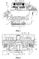
- a thread delivery device F preferably a thread delivery device F for a knitting machine, has a stationary housing G, on the underside of a storage drum T rotatably mounted which is about an axis of rotation X by means of a motor M in a predetermined direction of rotation to be driven.
- the Motor M can be switched on and off by means of signals, that of a scanning device D in a housing bracket 1 depending on the size of one on the storage drum T formed thread supply (not shown) are generated.
- the fed to the storage drum T by a not shown Supply spool coming thread (not shown) is through stationary Thread eyelets 2 passed and passed through a thread brake 3 under surveillance by a sensing element 5 to the extent the storage drum T.
- An inclined feed element V pushes each turn wound on the storage drum T. in Fig. 1 down, so that a thread supply of several Turns is formed.
- the thread intended for consumption is pulled off over the top of the storage drum.
- a backstop R is provided in the thread delivery device F, namely between an upper cover wall 6 of the housing G and the upper end of a motor shaft H.
- the backstop R contains in the embodiment of Fig. 1 with the motor shaft H rotatably connected abutment W and a relative to it rotatably supported by a weak coil spring 4 upward loaded blocking element S, which is used for cooperation provided with a braking surface B in the top wall 6 Insert 7 is used, namely a return or a Return movement of the storage drum T or the motor shaft H prevent after a standstill.
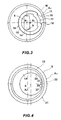
- the abutment W is an annular body A1 from a hub 8, which has a non-circular inner bore 9 attached to the matching end 10 of the motor shaft H in a rotationally fixed manner is a radial flange 11, which is a spring seat 12 defined, and an axial ring flange 14 with a cylindrical Outer peripheral surface 15, whose axis is opposite to X1 the axis of rotation X of the motor shaft H is eccentric. Further is in the annular flange 14 a cutout limited in the circumferential direction 17 molded, the (Fig. 3) two in the circumferential direction spaced stops 18 and 18 'defined. In the end area a circumferential bead 16 is formed on the ring flange 14.
- Locking member S that which is mounted on the abutment W relatively rotatably to this Locking member S is also an annular body A2, namely an annular disc 19 with an inner bore 20 and one cylindrical outer circumference 21, which is used for cooperation with the Braking area B is determined.
- the central axis of the peripheral surface 21 is correct in the running position of the backstop R with the axis of rotation X at least approximately.
- the annular disc 19 In one face the annular disc 19 is concentric with the peripheral surface 21 Spring receiving groove 13 formed for the coil spring 4, the other end in the spring seat 12 of the Flange 11 supports and the annular disc 19 with at least a part 22 of its other end face against a housing-fixed Drag surface 23 presses.
- a nose 26 In the inner bore 20 the annular disc 19 a nose 26 protrudes inwards, 4 stops 27 and 27 'defined with the Stops 18 and 18 'for setting a running position and cooperate in a locked position.
- the braking surface B and the Trailing surface 23 are included in the insert 7, which in the Cover wall 6 is set. It is conceivable the tow surface 23 and to arrange the braking surface 21 directly in the top wall 6.
- the braking surface B is on one Brake ring 24 made of a frictional material, such as rubber, elastomer or another plastic, provided in a Version 25 of insert 7 is set.
- a radial Game Y provided in the in Fig. 2 shown running position, in which the backstop R the normal rotation of the motor shaft H is not affected the peripheral surface 21 and the braking surface B a radial Game Y provided.
- the two ring bodies A1, A2 are expediently plastic parts, for example injection molded parts.
- the insert 7 can consist of metal, for example steel.
- the braking surface B could also be directly from the inner peripheral surface of the socket 25 are formed, which then expediently a roughened Surface structure, for example knurling, has.
- the peripheral surface 21 could, if necessary, be structured to increase the frictional engagement.
- the locking member S sits in accordance with FIG the rotational position shown in FIG. 4 on the ring flange 14 of the abutment W, which is in the rotational position shown in Fig. 3 located.
- the nose 26 is at the stop 27 ' Stop 18 'on.
- the peripheral surface 21 is then essentially concentric to the axis of rotation X and is the braking surface B (Fig. 2) with the radial play Y opposite. 3 and 4 counterclockwise motor shaft H takes the locking member S over the abutment w without it the braking surface B comes into contact. Because of the pressure the spring 8 becomes the locking member S against the drag surface 23 pressed so that a permanent Towing force in the locking element S acts in a clockwise direction stops with the stop 27 'at the stop 18'.
- a kinematic reversal is conceivable in such a way that the Ring body A2 on the top wall 6 or in the insert 7 rotatably is mounted, however, the ring body A1, the motor shaft H or the end 10 (which then has a cylindrical outer circumference has) rotatably comprises, expediently again with a radial play.
- the end surface 23 'then serves as the drag surface.
- the motor shaft H with the end face 22 'of the ring body A1 works together under the pressure of spring 4.
- the braking surface B can then either on the outer circumference of the motor shaft H or also provided in the inner bore 9 of the ring body A1 his.
- the ring body A2 forms the abutment W and the ring body A1 the locking member S.
- FIGS. 2, 3 and 4 are the embodiment shown in FIGS. 2, 3 and 4 schematically shown, in which the locking member S on the outside the abutment W is rotatably mounted and with the braking surface B works together.
- Fig. 6 the kinematic reversal is indicated, in which the abutment W arranged outside on the locking member S and (indicated by crosses) is rotatably held.
- the locking link S is rotatable relative to the motor shaft H.
- the blocking effect is between the inner bore 9 and the braking surface B or brought about the outer circumference of the motor shaft H.
- the schematic of the 5 is on the outer circumference 21st the locking member S is a limited braking surface area in the circumferential direction 21 'preformed, the to cooperation with the braking surface B is determined.
- the abutment W is here Ring body with a non-circular outer circumference, which is the definition of the Abutment simplified. 7 and 8, the braking surface area 21 'and 9' also have a curvature, the Center of curvature not with the center of the cylinder surface 21 or 9 coincides, i.e. the braking surface area 21 ' or 9 'could be curved more or less by one to achieve special braking effect.
- the backstop shown in Fig. 1 could also be below of the motor M may be arranged.
- the Backstop R however encapsulated and out of the influence of Soiling or fluff when processing thread material are inevitable, be separated.
- the diameter, on which the locking member interacts with the braking surface B, is advantageously much smaller than the diameter the storage drum T or its inner diameter.
- the size the contact area between the locking member and the Drag surface 23 or 23 ' should be chosen so that under the pressure of the spring 8 just sufficient for the function Tractive force guaranteed, however, overheating or a burning of the locking member is excluded.
Landscapes
- Engineering & Computer Science (AREA)
- Textile Engineering (AREA)
- Connection Of Motors, Electrical Generators, Mechanical Devices, And The Like (AREA)
- Knitting Machines (AREA)
- Braking Arrangements (AREA)
- Forwarding And Storing Of Filamentary Material (AREA)
- Tension Adjustment In Filamentary Materials (AREA)
Description
Die Erfindung betrifft ein Fadenliefergerät der im Oberbegriff
des Patentanspruchs 1 angegebenen Art.The invention relates to a thread delivery device in the preamble
of
Aus US-A-3 642 219 ist ein Fadenliefergerät dieser Art bekannt, das unter der Bezeichnung SFS/SFT seit über 20 Jahren vor der Anmelderin vertrieben wird. Die in der US-A-3 642 219 nur andeutungsweise erkennbare Rücklaufsperre ist zwischen der Deckwand des in die Speichertrommel integrierten Elektromotors und einer Drehlagerung eines Vorschubelements auf der gehäusefesten Welle angeordnet. Das Sperrglied arbeitet mit dem Innenumfang der Speichertrommel auf einem relativ großen Durchmesser zusammen. Bei diesem in der Praxis benutzten Fadenliefergerät SFS/SFT ist das Sperrglied eine aus Kunststoff bestehende Scheibe, die in einem gabelartigen, auf der Welle verankerten Widerlager zwischen der Laufstellung und der Bremsstellung verlagerbar ist, und zwar durch die zwischen einer Stirnseite der Scheibe und der oberen Abdeckung des Motors durch Reibungskontakt erzeugten Schleppkraft. Das Widerlager besitzt eine in Rücklaufrichtung ansteigende, konkave Gleitbahn für die Scheibe, und an beiden Enden der Laufbahn angeformte Anschläge. In der Laufstellung löst sich die Scheibe zumindest weitgehend aus dem Eingriff mit der am Innenumfang der Speichertrommel vorgesehenen Bremsfläche. Tritt ein Rücklauf der Speichertrommel auf, dann wird die Scheibe durch die Schleppkraft entlang der Gleitbahn in eine Sperrstellung verlagert, in der sie gegen die Bremsfläche gedrückt wird. Eine Rücklaufbewegung der Speichertrommel kann mehrere Ursachen haben. Ein im Zulaufbereich des Fadenliefergerätes vorgesehener Fadenabtaster ist federbeaufschlagt und kann nach Anhalten der Speichertrommel den zulaufenden Faden zurückziehen und die Speichertrommel mittels des Fadens zurückdrehen. Ferner sind die zu verarbeitenden Fäden zumeist elastisch, so daß beim Anhalten der Speichertrommel die zuvor im zulaufenden Faden erzeugte Spannung die Speichertrommel über den Faden zurückdrehen möchte. Schließlich kann infolge ungünstiger Umstände und aufgrund einer vorgenommenen Abbremsung des Motors ein Gegendrehmoment entstehen, das die Speichertrommel zurückdrehen möchte. Die bekannte Rücklaufsperre ist herstellungstechnisch aufwendig, verschleißanfällig und kann vor allem beim Beschleunigen oder bei höheren Geschwindigkeiten unerwünschte Vibrationen verursachen, unter anderem deshalb, weil die Scheibe auf einen extrem großen Durchmesser und mit sehr großem Hebelarm wirkt. Die bekannte Rücklaufsperre bedingt eine nahezu exakt vertikale Anordnung des Fadenliefergerätes, wie sie in manchen Anwendungsfällen nicht einhaltbar ist. Ferner sind baulich aufwendige Maßnahmen erforderlich, um ein Verbrennen der Scheibe an ihrer die obere Deckwand des Motors kontaktierenden Stirnseite zu verhindern, weil die Scheibe die Deckwand mit großem Abstand von der Drehachse berührt und deshalb bei hoher Geschwindigkeit eine beträchtliche Reibleistung zu vernichten ist..From US-A-3 642 219 a thread delivery device of this type is known, that has been known as SFS / SFT for over 20 years is distributed before the applicant. U.S. Patent No. 3,642,219 there is only a hint of backstop between the top wall of the electric motor integrated in the storage drum and a rotary bearing of a feed element on the shaft fixed to the housing. The locking member works with the inner circumference of the storage drum on a relatively large Diameter together. With this thread delivery device used in practice SFS / SFT is the locking member made of plastic existing disc, in a fork-like, on the shaft anchored abutment between the running position and the Brake position is shiftable, namely by between one face of the disc and the top cover of the engine towing force generated by frictional contact. The abutment has a rising concave in the return direction Slideway for the disc, and at both ends of the track molded stops. In the running position, the comes loose Disk at least largely out of engagement with that on the inner circumference the braking surface provided for the storage drum. Kick a return of the storage drum, then the disc by the drag force along the slideway in a locked position relocated in which they pressed against the braking surface becomes. A return movement of the storage drum can be several Have causes. One in the feed area of the thread delivery device The provided thread scanner is spring-loaded and can after stopping the storage drum pull back the incoming thread and turn the storage drum back with the thread. Furthermore, the threads to be processed are mostly elastic, so that when stopping the storage drum the previously in tapered thread generated tension over the storage drum want to turn the thread back. Eventually, as a result, less favorable Circumstances and due to a slowdown of the motor create a counter torque that the storage drum want to turn back. The well-known backstop is technically complex, prone to wear and tear can especially when accelerating or at higher speeds cause unwanted vibrations, among other things because the disc has an extremely large diameter and works with a very large lever arm. The well-known backstop requires an almost exactly vertical arrangement of the thread delivery device, like they don't in some use cases is observable. Furthermore, structurally complex measures are required to burn the disc at its top To prevent the top wall of the motor contacting end face because the disc covers the top wall at a great distance from the Axis of rotation touches and therefore at high speed considerable friction is to be destroyed ..
Der Erfindung liegt die Aufgabe zugrunde, ein Fadenliefergerät der eingangs erwähnten Art zu schaffen, bei dem eine baulich einfache, leicht zu montierende Rücklaufsperre vorgesehen ist, die verschleißarm mit langer Standzeit zuverlässig arbeitet und keine Vibrationen hervorruft.The invention has for its object a yarn delivery device of the type mentioned at the beginning, in which a structural simple, easy-to-assemble backstop provided is reliable, wear-resistant with a long service life works and does not cause vibrations.
Die gestellte Aufgabe wird erfindungsgemäß mit den im Patentanspruch
1 enthaltenen Merkmalen gelöst.The object is achieved according to the invention in the
Ein spürbarer Einfluß bei hohen Geschwindigkeiten des Drehelements ist wegen der genau einstellbaren Schleppkraft eliminiert. Dies ist insbesondere bei modernen Fadenliefergeräten von erheblichem Vorteil, deren Drehgeschwindigkeit um ca. 20% höher sein kann als bei bisher verwendeten Fadenliefergeräten. Die Bremsfläche läßt sich auf einen Durchmesser setzen, der deutlich kleiner sein kann als der Innendurchmesser einer gegebenenfalls vorgesehenen Speichertrommel. Zeigt das Drehelement die Tendenz einer Rücklaufbewegung, dann wird das Sperrglied relativ zum Widerlager in einer leichtgängigen Drehbewegung durch die Schleppkraft verdreht, bis sein Gegenbremsbereich dank des zur Drehachse des Drehelementes exzentrischen Kreises nach außen oder nach innen gegen die Bremsfläche anläuft und die Rücklaufbewegung sperrt. Der Eingriff in die Sperrstellung erfolgt harmonisch und zuverlässig, wobei eine hohe Bremsleistung erzeugbar ist. Besonders wichtig ist, daß sich das Sperrglied beim Wiederanlaufen des Drehelementes in der ordnungsgemäßen Drehrichtung leicht und zwangsweise von der Bremsfläche löst und wieder in die definierte Laufstellung zurückkehrt. Der Eingriffsbereich zwischen dem Sperrglied und der Bremsfläche läßt sich großflächig gestalten, so daß keine Anregung zu Vibrationen im Fadenliefergerät entsteht. Die Rücklaufsperre arbeitet verschleißarm und zuverlässig mit langer Standzeit. Allgemein soll hervorgehoben sein, daß durch die Exzentrizität und den Durchmesser des exzentrischen Kreises die Kennlinie genau vorherbestimmbar und optimal auslegbar ist, mit der die Rücklaufsperre zur Wirkung kommt bzw. wieder gelöst wird.A noticeable influence at high speeds of the rotating element is eliminated due to the precisely adjustable towing force. This is particularly the case with modern thread delivery devices of considerable advantage, the rotation speed of which is approx. 20% can be higher than in the yarn delivery devices previously used. The braking surface can be set to a diameter which can be significantly smaller than the inside diameter of one if applicable, provided storage drum. Shows the rotating element the tendency to move backwards, then it will Locking element relative to the abutment in a smooth-running Rotational movement twisted by the drag force until its counter braking range thanks to the eccentric to the axis of rotation of the rotating element Circle outwards or inwards against the braking surface starts and blocks the return movement. The engagement in the blocking position takes place harmoniously and reliably, whereby a high braking power can be generated. Particularly important is that the locking member when restarting the rotary element easily and forcibly in the correct direction of rotation detaches from the braking surface and returns to the defined one Run position returns. The area of engagement between the Locking element and the braking surface can be designed over a large area, so that no excitation to vibrations in the thread delivery device arises. The backstop works reliably and with little wear with a long service life. General should be highlighted be that by the eccentricity and the diameter of the eccentric Circle, the characteristic curve can be predetermined precisely and can be optimally designed with which the backstop takes effect comes or is solved again.
Gemäß Anspruch 2 wird die Rücklaufsperre auf einem optimal
kleinen Durchmesser vorgenommen, und insbesondere auf einem
von der Größe der Speichertrommel unabhängigen Durchmesser.According to
Die Schleppkraft läßt sich gemäß Anspruch 3 exakt durch die
Bemessung der Federkraft vorherbestimmen. Zweckmäßigerweise
erfolgt das Andrücken entgegen der Wirkung der Schwerkraft.
Das Fadenliefergerät läßt sich deshalb in beliebigen Einbaulagen
ohne Gefährdung der Rücklaufsperrung einsetzen. Ferner
läßt sich der Bereich, in dem das Sperrglied die Schleppfläche
kontaktiert, relativ nahe an die Drehachse des Drehelements
setzen, so daß auch bei hohen Drehgeschwindigkeiten und
starken Beschleunigungen die Gefahr eines Verbrennens des
Sperrglieds vermieden wird, auch durch die Ringform, die eine
relativ geringe spezifische Flächenpressung pro Flächeneinheit
ermöglicht und trotzdem die ausreichende Schleppkraft
gewährleistet.The towing force can be exactly according to
Obwohl das Sperrelement selbsttätig in die gerade zum Verhindern
des Rücklaufs erforderliche Sperrstellung verdreht wird,
ohne daß es eines speziellen Anschlages für die Sperrstellung
bedürfte, kann es zweckmäßig sein, gemäß Anspruch 4 einen eigenen
Anschlag für das Sperrglied vorzusehen, der eine Endsperrstellung
definiert und übergroße Kräfte auf die Bremsfläche
bzw. das Drehelement verhindert.Although the locking element automatically in the straight to prevent
the blocking position required for the return is turned,
without there being a special stop for the locking position
need, it may be appropriate, according to
Besonders zweckmäßig ist die Ausführungsform gemäß Anspruch
5, bei der der Motor im Gehäuse fest angeordnet und die Rücklaufsperre
gut gekapselt vom Arbeitsbereich der Speichertrommel
getrennt ist, in dem Verschmutzungen und Flusen unvermeidbar
sind. Da das Sperrglied keine Zusammenarbeit mit dem
Innendurchmesser der Speichertrommel hat, läßt sich der
Durchmesser der Bremsfläche klein genug wählen, um bei hohen
Geschwindigkeiten und starken Beschleunigungen in modernen
Fadenliefergeräten Vibrationen auszuschließen.The embodiment according to claim is particularly
Gemäß Anspruch 6, wird die Motorwelle über die mitlaufende
Rücklaufsperre am Gehäuse gegen einen Rücklauf abgestützt.According to
Alternativ macht gemäß Anspruch 7 die Rücklaufsperre die Drehbewegung des Drehelementes nicht mit, sondern wirkt erst bei einem Rücklauf, um die Motorwelle über die beispielsweise an der Motorwelle angebrachte Bremsfläche zu blockieren.Alternatively, the backstop makes according to claim 7 Rotary movement of the rotating element does not co-operate, but acts first with a return to the motor shaft over the for example block the braking surface attached to the motor shaft.
Gemäß Anspruch 8 arbeitet das Sperrglied mit einem Bremsring
zusammen, der u.a. materialbedingt eine hohe Bremswirkung erbringt.According to
Alternativ könnte ein Bremsring direkt auf dem oder in dem Sperrglied angebracht sein (Anspruch 9). Alternatively, a brake ring could be placed directly on or in the Locking member can be attached (claim 9).
Eine gute Rücklaufsperrung wird gemäß Anspruch 10 auch mit
einer Bremsfläche erreicht, die nur strukturiert, zum Beispiel
gerändelt ist. Diese Bremsfläche kann in einem metallischen
Körper angeornet sein, zum Beispiel im Gehäuse oder in
einem Gehäuseeinsatz.A good backstop is also according to
Herstellungstechnisch einfach ist die Ausführungsform gemäß
Anspruch 11. Kunststofformteile zeichnen sich durch hohe
Formgenauigkeit, geringes Gewicht und hohe Verschleißarmut
aus. Da das Sperrglied durch genau einstellbare Federkraft an
die Schleppfläche gedrückt wird, können selbstschmierende
Kunststoffqualitäten benutzt werden, die eine leichtgängige
Verdrehbarkeit des Sperrgliedes auch über lange Standzeit gewährleisten.
Der selbstschmierende Effekt hat auf die Bremswirkung
mit der Bremsfläche keine nachteiligen Einfluß, weil
dort durch die exzentrische Versetzbewegung des Sperrglieds
ohnedies ein rasch wirkender Zwangseingriff herstellbar ist.The embodiment according to FIG
Die Ausführungsform gemäß Anspruch 12 ist baulich einfach und
gewährleistet ein verschleißarmes Arbeiten auch über lange
Standzeit.The embodiment according to
Gemäß Anspruch 13 ist die Feder zwischen der Kreisringscheibe
und der Nabe als integrierter Bestandteil der Rücklaufsperre
angeordnet. Die Vorsprünge bzw. der Umfangswulst sind eine
Montagehilfe für eine vormintierbare Baueinheit, weil die
Kreisringscheibe unter der Kraft der Feder nicht vom Ringflansch
abfallen kann. Im Betrieb gelangt die Kreisringscheibe
normalerweise nicht zu den Vorsprüngen bzw. zu dem Umfangswulst.According to
Anhand der Zeichnung werden Ausführungsformen des Erfindungsgegenstandes erläutert. Es zeigen:
- Fig. 1
- eine Seitenansicht, zum Teil im Schnitt, eines Fadenliefergeräts mit einer Rücklaufsperre,
- Fig. 2
- die Rücklaufsperre in einem Schnitt und in vergrößertem Maßstab, in der Laufstellung,
- Fig. 3
- eine axiale Draufsicht auf ein Widerlager der Rücklaufsperre,
- Fig. 4
- eine axiale Draufsicht auf ein Sperrglied der Rücklaufsperre, das zum Widerlager der Fig. 3 paßt, und
- Fig. 5-8
- schematische Detailvarianten der Rücklaufsperre.
- Fig. 1
- a side view, partly in section, of a yarn delivery device with a backstop,
- Fig. 2
- the backstop in one section and on an enlarged scale, in the running position,
- Fig. 3
- an axial plan view of an abutment of the backstop,
- Fig. 4
- an axial plan view of a locking member of the backstop, which fits the abutment of FIG. 3, and
- Fig. 5-8
- schematic detailed variants of the backstop.
Ein Fadenliefergerät F, vorzugsweise ein Fadenliefergerät F
für eine Strickmaschine, weist ein stationäres Gehäuse G auf,
an dem unterseitig eine Speichertrommel T drehbar gelagert
ist, die um eine Drehachse X mittels eines Motors M in einer
vorbestimmten Drehrichtung zur Drehung antreibbar ist. Der
Motor M ist ein- und ausschaltbar, und zwar mittels Signalen,
die von einer Abtastvorrichtung D in einem Gehäuseausleger 1
in Abhängigkeit von der Größe eines auf der Speichertrommel T
gebildeten Fadenvorrats (nicht gezeigt) erzeugt werden. Der
der Speichertrommel T zugeführte, von einer nicht gezeigten
Vorratsspule kommende Faden (nicht gezeigt) wird durch stationäre
Fadenösen 2 durch eine Fadenbremse 3 geleitet und gelangt
unter Überwachung durch ein Tastelement 5 zum Umfang
der Speichertrommel T. Ein schräggestelltes Vorschubelement V
schiebt jede auf der Speichertrommel T aufgewickelte Windung
in Fig. 1 nach unten, so daß ein Fadenvorrat aus mehreren
Windungen gebildet wird. Der zum Verbrauch bestimmte Faden
wird über Kopf der Speichertrommel abgezogen.A thread delivery device F, preferably a thread delivery device F
for a knitting machine, has a stationary housing G,
on the underside of a storage drum T rotatably mounted
which is about an axis of rotation X by means of a motor M in a
predetermined direction of rotation to be driven. The
Motor M can be switched on and off by means of signals,
that of a scanning device D in a
In dem Fadenliefergerät F ist eine Rücklaufsperre R vorgesehen,
und zwar zwischen einer oberen Deckwand 6 des Gehäuses G
und dem oberen Ende einer Motorwelle H. Die Rücklaufsperre R
enthält bei der Ausführungsform der Fig. 1 ein mit der Motorwelle
H drehfest verbundenes Widerlager W und ein darauf relativ
verdrehbar gelagertes, durch eine schwache Schraubenfeder
4 nach oben belastetes Sperrglied S, das zur Zusammenarbeit
mit einer Bremsfläche B eines in der Deckwand 6 vorgesehen
Einsatzes 7 dient, und zwar um einen Rücklauf bzw. eine
Rücklaufbewegung der Speichertrommel T bzw. der Motorwelle H
nach einem Stillstand zu verhindern.A backstop R is provided in the thread delivery device F,
namely between an
Gemäß Fig. 2 ist das Widerlager W ein Ringkörper Al, bestehend
aus einer Nabe 8, die mit einer unrunden Innenbohrung 9
auf das dazu passende Ende 10 der Motorwelle H drehfest aufgesteckt
ist, einem radialen Flansch 11, der einen Federsitz
12 definiert, und einem axialen Ringflansch 14 mit einer zylindrischen
Außenumfangsfläche 15, deren Achse X1 gegenüber
der Drehachse X der Motorwelle H exzentrisch ist. Ferner ist
in dem Ringflansch 14 ein in Umfangsrichtung begrenzter Ausschnitt
17 eingeformt, der (Fig. 3) zwei in Umfangsrichtung
beabstandete Anschläge 18 und 18' definiert. Im Endbereich
des Ringflansches 14 ist ein umlaufender Wulst 16 angeformt.2, the abutment W is an annular body A1
from a
Das auf dem Widerlager W zu diesem relativ verdrehbar gelagerte
Sperrglied S ist ebenfalls ein Ringkörper A2, und zwar
eine Kreisringscheibe 19 mit einer Innenbohrung 20 und einem
zylindrischen Außenumfang 21, der zur Zusammenarbeit mit der
Bremsfläche B bestimmt ist. Die Mittelachse der Umfangsfläche
21 stimmt in der gezeigten Laufstellung der Rücklaufsperre R
mit der Drehachse X zumindest in etwa überein. Die Mittelachse
der Innenbohrung 20 stimmt hingegen mit der Achse X1 überein,
die zur Drehachse X exzentrisch ist. In einer Stirnseite
der Kreisringscheibe 19 ist eine zur Umfangsfläche 21 konzentrische
Federaufnahmenut 13 für die Schraubenfeder 4 eingeformt,
die sich mit ihrem anderen Ende im Federsitz 12 des
Flansches 11 abstützt und die Kreisringscheibe 19 mit zumindest
einem Teil 22 ihrer anderen Stirnfläche gegen eine gehäusefeste
Schleppfläche 23 andrückt. In der Innenbohrung 20
der Kreisringscheibe 19 tritt eine Nase 26 nach innen vor,
die gemäß Fig. 4 Anschläge 27 bzw. 27' definiert, die mit den
Anschlägen 18 und 18' zum Festlegen einer Laufstellung und
einer Sperrstellung zusammenwirken. Die Bremsfläche B und die
Schleppfläche 23 sind in dem Einsatz 7 enthalten, der in der
Deckwand 6 festgelegt ist. Es ist denkbar, die Schleppfläche
23 und die Bremsfläche 21 direkt in der Deckwand 6 anzuordnen.That which is mounted on the abutment W relatively rotatably to this
Locking member S is also an annular body A2, namely
an
Die Bremsfläche B ist bei dieser Ausführungsform an einem
Bremsring 24 aus reibungsaktivem Werkstoff, wie Gummi, Elastomer
oder einem anderen Kunststoff, vorgesehen, der in einer
Fassung 25 des Einsatzes 7 festgelegt ist. In der in Fig.
2 dargestellten Laufstellung, in der die Rücklaufsperre R die
normale Drehung der Motorwelle H nicht beeinflußt, ist zwischen
der Umfangsfläche 21 und der Bremsfläche B ein radiales
Spiel Y vorgesehen.In this embodiment, the braking surface B is on one
Die beiden Ringkörper A1, A2 sind zweckmäßigerweise Kunststoffteile,
zum Beispiel Spritzgußteile. Der Einsatz 7 kann
aus Metall bestehen, zum Beispiel aus Stahl. Die Bremsfläche
B könnte auch direkt von der Innenumfangsfläche der Fassung
25 gebildet werden, die dann zweckmäßigerweise eine aufgerauhte
Oberflächenstruktur, zum Beispiel eine Rändelung, besitzt.
Auch die Umfangsfläche 21 könnte, falls erforderlich,
strukturiert sein, um den Reibungseingriff zu verstärken.The two ring bodies A1, A2 are expediently plastic parts,
for example injection molded parts. The
In der Laufstellung sitzt das Sperrglied S gemäß Fig. 4 in
der in Fig. 4 gezeigten Drehposition auf dem Ringflansch 14
des Widerlagers W, das sich in der in Fig. 3 gezeigten Drehposition
befindet. Die Nase 26 steht mit dem Anschlag 27' am
Anschlag 18' an. Die Umfangsfläche 21 ist dann im wesentlichen
konzentrisch zur Drehachse X und steht der Bremsfläche B
(Fig. 2) mit dem Radialspiel Y gegenüber. Die in den Fig. 3
und 4 entgegen dem Uhrzeigersinn angetriebene Motorwelle H
nimmt über das Widerlager w das Sperrglied S mit, ohne daß es
zu einer Berührung der Bremsfläche B kommt. Durch den Druck
der Feder 8 wird das Sperrglied S gegen die Schleppfläche 23
angedrückt, so daß durch Reibungskontakt eine permanente
Schleppkraft im Sperrglied S wirkt, die dieses im Uhrzeigersinn
mit dem Anschlag 27' am Anschlag 18' hält.In the running position, the locking member S sits in accordance with FIG
the rotational position shown in FIG. 4 on the
Nach einem Stillstand der Motorwelle H wird im Falle eines
Rücklauf es (Drehbewegung des Motorwelle H in den Fig. 3 und 4
im Uhrzeigersinn) durch den Kontakt mit der Schleppfläche 23
am Sperrglied S eine Schleppkraft entgegen dem Uhrzeigersinn
erzeugt. Dieses Schleppkraft verdreht das Sperrglied S relativ
zum Widerlager W auf dem Ringflansch 14, wobei die Außenumfangsfläche
21 des Sperrgliedes in einem in Umfangsrichtung
begrenzten Gegenbremsbereich nach außen verlagert wird und an
der Bremsfläche B anläuft. Eine weitere Rücklaufbewegung der
Motorwelle H wird auf diese Weise verhindert. Gegebenenfalls
gelangt sogar der Anschlag 27 der Nase 26 zur Anlage am Anschlag
18 des Ringflansches 14.After the motor shaft H has come to a standstill, in the event of a
Return it (rotary movement of the motor shaft H in FIGS. 3 and 4
clockwise) by contact with the towing
Wird die Motorwelle H wieder in der gewünschten Richtung angetrieben,
d.h. in den Fig. 3 und 4 entgegen dem Uhrzeigersinn,
dann hält die Schleppkraft an der Schleppfläche 23 das
Sperrglied S zurück, die Umfangsfläche 21 wird von der Bremsfläche
B gelöst und zentriert sich erneut in bezug auf die
Drehachse X.If the motor shaft H is driven in the desired direction again,
i.e. 3 and 4 counterclockwise,
then the towing force on the towing
Eine kinematische Umkehrung dergestalt ist denkbar, daß der
Ringkörper A2 an der Deckwand 6 bzw. im Einsatz 7 drehfest
gelagert ist, hingegen der Ringkörper A1 die Motorwelle H
oder deren Ende 10 (die dann einen zylindrischen Außenumfang
hat) drehbar umfaßt, zweckmäßigerweise wieder mit einem Radialspiel.
Als Schleppfläche dient dann die Stirnfläche 23'
der Motorwelle H, die mit der Stirnfläche 22' des Ringkörpers
A1 unter dem Druck der Feder 4 zusammenarbeitet. Die Bremsfläche
B kann dann entweder am Außenumfang der Motorwelle H
oder auch in der Innenbohrung 9 des Ringkörpers A1 vorgesehen
sein. In diesem Fall bildet der Ringkörper A2 das Widerlager
W und der Ringkörper A1 das Sperrglied S. A kinematic reversal is conceivable in such a way that the
Ring body A2 on the
In Fig. 5 ist die in Fig. 2, 3 und 4 gezeigte Ausführungsform schematisch dargestellt, bei der das Sperrglied S außen auf dem Widerlager W drehbar gelagert ist und mit der Bremsfläche B zusammenarbeitet.5 is the embodiment shown in FIGS. 2, 3 and 4 schematically shown, in which the locking member S on the outside the abutment W is rotatably mounted and with the braking surface B works together.
In Fig. 6 ist die kinematische Umkehruna angedeutet, bei der
das Widerlager W außen auf dem Sperrglied S angeordnet und
(durch Kreuze angedeutet) drehfest gehaltert ist. Das Sperrglied
S ist relativ zur Motorwelle H drehbar. Die Sperrwirkung
wird zwischen der Innenbohrung 9 und der Bremsfläche B
bzw. dem Außenumfang der Motorwelle H herbeigeführt.In Fig. 6 the kinematic reversal is indicated, in which
the abutment W arranged outside on the locking member S and
(indicated by crosses) is rotatably held. The locking link
S is rotatable relative to the motor shaft H. The blocking effect
is between the
Bei der Ausführungsform gemäß Fig. 7, die schematisch dem Funktionsprinzip der Fig. 5 entspricht, ist am Außenumfang 21 der Sperrglieds S ein in Umfangsrichtung begrenzter Bremsflächen-Bereich 21' vortretend angeformt, der zur Zusammenarbeit mit der Bremsfläche B bestimmt ist.7, the schematic of the 5 is on the outer circumference 21st the locking member S is a limited braking surface area in the circumferential direction 21 'preformed, the to cooperation with the braking surface B is determined.
Ähnlich ist bei der Ausführungsform der Fig. 8, die dem Funktionsprinzip
der Fig. 6 entspricht in den Innenbohrung 9 des
Sperrgliedes ein in Umfangsrichtung begrenzter, nach innen
vorspringender Bremsflächenbereich 9' angeformt, der zur Zusammenarbeit
mit der Bremsfläche B, im vorliegenden Fall auf
der Motorwelle H, bestimmt ist. Das Widerlager W ist hier ein
Ringkörper mit unrundem Außenumfang, was die Festlegung des
Widerlagers vereinfacht. In den Fig. 7 und 8 kann der Bremsflächenbereich
21' bzw. 9' auch eine Krümmung aufweisen, deren
Krümmungszentrum nicht mit dem Zentrum der Zylinderfläche
21 bzw. 9 zusammenfällt, d.h. der Bremsflächenbereich 21'
bzw. 9' könnte stärker oder schwächer gekrümmt sein, um eine
spezielle Bremswirkung erzielen zu können.8 is similar to the principle of
Die in Fig. 1 gezeigte Rücklaufsperre könnte auch unterhalb
des Motors M angeordnet sein. Zweckmäßigerweise sollte die
Rücklaufsperre R jedoch gekapselt und vom Einflußbereich von
Verschmutzungen oder Flusen, die beim Verarbeiten von Fadenmaterial
unvermeidbar sind, separiert sein. Der Durchmesser,
an dem das Sperrglied mit der Bremsfläche B zusammenwirkt,
ist vorteilhafterweise wesentlich kleiner als der Durchmesser
der Speichertrommel T bzw. deren Innendurchmesser. Die Größe
des Kontaktbereichs zwischen dem Sperrglied und der
Schleppfläche 23 bzw. 23' sollte so gewählt werden, daß unter
dem Druck der Feder 8 eine gerade für die Funktion ausreichend
Schleppkraft gewährleistet, hingegen eine Überhitzung
oder ein Verbrennen des Sperrgliedes ausgeschlossen ist.The backstop shown in Fig. 1 could also be below
of the motor M may be arranged. Conveniently, the
Backstop R however encapsulated and out of the influence of
Soiling or fluff when processing thread material
are inevitable, be separated. The diameter,
on which the locking member interacts with the braking surface B,
is advantageously much smaller than the diameter
the storage drum T or its inner diameter. The size
the contact area between the locking member and the
Claims (13)
- Yarn feeder (F), particularly for knitting machines, having a stationary housing (G) and a rotational element (T) which can be driven in a rotational direction by means of a motor (M) which can be switched off and switched on, said rotational element (T) being supported on the housing and serving to wind a yarn into a yarn store consisting of a plurality of windings on a storing surface from which the yarn can be withdrawn for consumption overhead, furthermore having a sensor device for detecting movements of the boundary of the yarn store varying in withdrawal direction and for generating signals to switch on or switch off the motor, and having a mechanical backturn-detent-mechanism for hindering a backturn movement of the rotational element, said mechanism containing a detent member (S) which is moveable in relation to a counter-member (W) between a running position defined by an abutment and a blocking position, for engaging a braking surface in the blocking position, said detent member (S), upon a rotational movement of the rotational element in each sense of rotation, being adapted to be brought into the running position or into the blocking position with a drag power generated by friction contact, said drag power displacing the detent member in response to the sense of rotation in relation to the counter-member, characterised in that the counter member (W) and the detent member (S) are two ring bodies which are set within each other and are rotatable in relation to each other about the rotational axis (X) of the rotational element (T), that the mutual area of engagement between the two ring bodies is at least a section of a circle being eccentrically arranged about the rotational axis of the rotational element, and that the detent member (S) for co-operation with the braking surface (B) is provided at its peripheral surface (21) with a braking range (21') being limited in its extent in circumferential direction.
- Yarn feeder as in claim 1, characterised in that the diameter of the braking surface (B) is significantly smaller than the inner diameter of the storing drum (T).
- Yarn feeder as in claim 1, characterised in that a front surface of the ring body (A1 or A2) defining the detent member (S) can be pressed by spring force (4) approximately parallel to the rotational axis (X) of the rotational element against a drag surface (23, 23') being fixed in the housing or fixed at the rotational element.
- Yarn feeder as in claim 1, characterised in that in addition to the abutment defining the running position an abutment for limiting the relative rotational movement between the ring bodies is provided for defining a blocking position, preferably a final blocking position.
- Yarn feeder as in at least one of claims 1 to 4, characterised in that the rotational element is a motor shaft (H) of the motor (M) arranged inside housing (G), said motor shaft (H) fixedly carrying a storing drum (T), and that the backturn-detent mechanism (R) is provided between a housing wall (6) facing away from storing drum (T) and the motor (M), preferably on an extension (10) of the motor shaft (H).
- Yarn feeder as in claim 5, characterised in that the ring body (A1) defining the counter-member (W) is fixedly arranged on the motor shaft (H), that the ring body (A2) defining the detent member (S) is supported at the exterior of the counter-member ring body, and that the braking surface (B) outside the detent member (S) as well as the drag surface (23) facing a front surface of the detent member (S) are provided in the housing wall (6), preferably in an insert (7) held in the housing wall (6).
- Yarn feeder as in claim 5, characterised in that the ring body (A1) defining the counter member (W) is fixedly held in the housing wall (6), preferably in a seat of the housing wall (6), that the ring body (A2) defining the detent member (S) is journalled inside in the counter member-ring body, and that the braking surface (B) inside the detent member (S) and the drag surface (23') facing a front surface of the detent member (S) are each provided on the motor shaft (H), preferably in an insert held by the motor shaft (H).
- Yarn feeder as in claim 6 or 7, characterised in that the braking surface (B) is formed by a braking ring (24) made of a friction-active material, e.g. rubber or elastomer, said braking ring surrounding the detent member (S) or being surrounded by the detent member (S), preferably with a radial clearance (Y) in the running position.
- Yarn feeder as in at least one of claims 1 to 7, characterised in that a braking ring (24) made of friction-active material is provided on the outside or within the detent member (S).
- Yarn feeder as in at least one of claims 1 to 7, characterised in that the braking surface (24, 25) is provided with a surface structure, e.g. a knurling.
- Yarn feeder as in at least one of claims 1 to 10, characterised in that both ring bodies (A1, A2) are form parts of plastics.
- Yarn feeder as in claims 5 and 6, characterised in that the counter-member ring body comprises a hub (8) fixedly secured to the motor shaft (H), preferably by means of a polygonal inner bore (9), said hub (8) having an axial annular flange (14) with a cylindrical outer peripheral surface (15) excentrically arranged about the rotational axis (X) of the motor shaft (H) and a radial flange (11) defining a spring seat (12), and that in the outer peripheral surface (15) of the annular flange (14) two circumferentially spaced-apart abutments are formed which are retracted in relation to the outer peripheral surface or protrude over said peripheral surface (15), and that the detent member-ring body is an annular disc (19) with a cylindrical outer peripheral surface (21) and an eccentric inner bore (20) which is eccentrically arranged in relation to the centre of the outer peripheral surface (21) and the inner diameter of which corresponds to the outer diameter of the ring flange (14) of hub (8), and that the inner bore (20) has arranged therein an inwardly projecting nose (26) or a diameter enlargement which is limited in circumferential direction.
- Yarn feeder as in claim 12, characterised in that in the front surface of the annular disc (19) facing the flange (11) a spring receiving groove (13) for a coil spring (4) is provided concentrically about the rotational axis (X) of the motor shaft (H), that the other end of the spring (4) is resting on the spring seat (12) of flange (11) of the hub (8), and that in the region of the free end of the ring flange (14) projections or a circumferential enlargement (16) is/are formed which slightly project(s) beyond the outer diameter of the ring flange.
Applications Claiming Priority (3)
| Application Number | Priority Date | Filing Date | Title |
|---|---|---|---|
| DE19538449 | 1995-10-16 | ||
| DE19538449A DE19538449A1 (en) | 1995-10-16 | 1995-10-16 | Thread delivery device |
| PCT/EP1996/004409 WO1997014836A1 (en) | 1995-10-16 | 1996-10-10 | Thread feed device |
Publications (2)
| Publication Number | Publication Date |
|---|---|
| EP0856074A1 EP0856074A1 (en) | 1998-08-05 |
| EP0856074B1 true EP0856074B1 (en) | 2000-01-19 |
Family
ID=7774958
Family Applications (1)
| Application Number | Title | Priority Date | Filing Date |
|---|---|---|---|
| EP96934622A Expired - Lifetime EP0856074B1 (en) | 1995-10-16 | 1996-10-10 | Thread feed device |
Country Status (7)
| Country | Link |
|---|---|
| US (1) | US6015109A (en) |
| EP (1) | EP0856074B1 (en) |
| KR (1) | KR100282545B1 (en) |
| CN (1) | CN1065933C (en) |
| DE (1) | DE59604253D1 (en) |
| ES (1) | ES2142621T3 (en) |
| TW (1) | TW475602U (en) |
Families Citing this family (5)
| Publication number | Priority date | Publication date | Assignee | Title |
|---|---|---|---|---|
| DE19840727A1 (en) * | 1998-09-07 | 2000-05-25 | Memminger Iro Gmbh | Thread delivery device for textile machines |
| DE10113184B4 (en) * | 2001-02-26 | 2006-04-20 | Memminger-Iro Gmbh | Knitting machine thread feed unit has a lever spring-operated moving end-stop |
| DE10234545B4 (en) * | 2002-07-30 | 2005-12-15 | Memminger-Iro Gmbh | Method and device for delivering threads |
| KR100734910B1 (en) * | 2005-10-25 | 2007-07-03 | 송유철 | Circular knitting machine with mechanical yarn storage |
| CN101768833B (en) * | 2008-12-31 | 2012-03-28 | 典洋针织机械股份有限公司 | Mechanical irregular yarn feeding device |
Family Cites Families (7)
| Publication number | Priority date | Publication date | Assignee | Title |
|---|---|---|---|---|
| US2685350A (en) * | 1950-12-21 | 1954-08-03 | Falk Corp | Reverse rotation stop |
| SE314157B (en) * | 1967-10-20 | 1969-09-01 | K Rosen | |
| DE1909737A1 (en) * | 1969-02-26 | 1970-09-17 | Rosen Karl I J | Yarn storage and delivery device for textile machines |
| DE2312508C3 (en) * | 1973-03-13 | 1975-10-16 | Ab Iro, Ulricehamn (Schweden) | Thread delivery device for the intermittent thread feed to textile machines, in particular weaving machines |
| DE2725185C2 (en) * | 1977-06-03 | 1979-05-23 | Ab Iro, Ulricehamn (Schweden) | Yarn storage and delivery device |
| CH623545A5 (en) * | 1977-01-17 | 1981-06-15 | Iro Ab | |
| SE511091C2 (en) * | 1993-04-21 | 1999-08-02 | Sipra Patent Beteiligung | Yarn feeder for textile machines |
-
1996
- 1996-10-10 KR KR1019980702749A patent/KR100282545B1/en not_active Expired - Lifetime
- 1996-10-10 DE DE59604253T patent/DE59604253D1/en not_active Expired - Fee Related
- 1996-10-10 EP EP96934622A patent/EP0856074B1/en not_active Expired - Lifetime
- 1996-10-10 US US09/051,066 patent/US6015109A/en not_active Expired - Fee Related
- 1996-10-10 ES ES96934622T patent/ES2142621T3/en not_active Expired - Lifetime
- 1996-10-10 CN CN96197658A patent/CN1065933C/en not_active Expired - Lifetime
- 1996-10-11 TW TW088211675U patent/TW475602U/en not_active IP Right Cessation
Also Published As
| Publication number | Publication date |
|---|---|
| ES2142621T3 (en) | 2000-04-16 |
| EP0856074A1 (en) | 1998-08-05 |
| KR19990064260A (en) | 1999-07-26 |
| CN1200152A (en) | 1998-11-25 |
| CN1065933C (en) | 2001-05-16 |
| DE59604253D1 (en) | 2000-02-24 |
| TW475602U (en) | 2002-02-01 |
| US6015109A (en) | 2000-01-18 |
| KR100282545B1 (en) | 2001-02-15 |
Similar Documents
| Publication | Publication Date | Title |
|---|---|---|
| DE69132780T2 (en) | yarn feeder | |
| DE69608445T2 (en) | SAFETY BELT REEL | |
| DE3922339C1 (en) | ||
| EP1640636A2 (en) | Belt tensioner with high damping | |
| DE2315392A1 (en) | THREAD HANDLING DEVICE | |
| DE4427683A1 (en) | Automatic tensioning element | |
| DE2461746C2 (en) | Yarn feeding device for textile machines | |
| EP0856074B1 (en) | Thread feed device | |
| DE19715944B4 (en) | pullstarter | |
| DE4123785B4 (en) | Electric motor, esp. For a windshield wiper system of a motor vehicle | |
| DE102006048742B4 (en) | Device on a drafting system of a spinning machine for loading the drafting system rollers, with at least one pressure cylinder | |
| DE2317234A1 (en) | SEMI-AUTOMATIC LEVELING DEVICE FOR FISHING | |
| EP1518810B1 (en) | Yarn brake and textile machine and yarn feeding device equipped with such a yarn brake | |
| EP3217053B1 (en) | Rotary drive, disc valve and beverage dispensing machine | |
| DE3139350C2 (en) | ||
| DE19538449A1 (en) | Thread delivery device | |
| EP1966421A1 (en) | Open-end spinning rotor for textile machine producing cross-wound packages | |
| EP3587643B1 (en) | Thread delivery device and system with such a device | |
| DE4007828C1 (en) | ||
| DE1710035B2 (en) | Device for drawing off and winding up a thread on an open-end spinning device | |
| DE2651357A1 (en) | REEL HOLDER | |
| EP0262443B1 (en) | Tube disc | |
| DE3219881A1 (en) | Yarn monitor in textile machines | |
| DE2452939C2 (en) | Swivel spindle | |
| CH640021A5 (en) | FALLSTITCH MECHANISM ON SEWING MACHINE. |
Legal Events
| Date | Code | Title | Description |
|---|---|---|---|
| PUAI | Public reference made under article 153(3) epc to a published international application that has entered the european phase |
Free format text: ORIGINAL CODE: 0009012 |
|
| 17P | Request for examination filed |
Effective date: 19980327 |
|
| AK | Designated contracting states |
Kind code of ref document: A1 Designated state(s): DE ES FR IT NL SE |
|
| GRAG | Despatch of communication of intention to grant |
Free format text: ORIGINAL CODE: EPIDOS AGRA |
|
| 17Q | First examination report despatched |
Effective date: 19981113 |
|
| GRAG | Despatch of communication of intention to grant |
Free format text: ORIGINAL CODE: EPIDOS AGRA |
|
| GRAH | Despatch of communication of intention to grant a patent |
Free format text: ORIGINAL CODE: EPIDOS IGRA |
|
| GRAH | Despatch of communication of intention to grant a patent |
Free format text: ORIGINAL CODE: EPIDOS IGRA |
|
| GRAA | (expected) grant |
Free format text: ORIGINAL CODE: 0009210 |
|
| AK | Designated contracting states |
Kind code of ref document: B1 Designated state(s): DE ES FR IT NL SE |
|
| REF | Corresponds to: |
Ref document number: 59604253 Country of ref document: DE Date of ref document: 20000224 |
|
| ITF | It: translation for a ep patent filed | ||
| ET | Fr: translation filed | ||
| REG | Reference to a national code |
Ref country code: ES Ref legal event code: FG2A Ref document number: 2142621 Country of ref document: ES Kind code of ref document: T3 |
|
| PLBE | No opposition filed within time limit |
Free format text: ORIGINAL CODE: 0009261 |
|
| STAA | Information on the status of an ep patent application or granted ep patent |
Free format text: STATUS: NO OPPOSITION FILED WITHIN TIME LIMIT |
|
| 26N | No opposition filed | ||
| PGFP | Annual fee paid to national office [announced via postgrant information from national office to epo] |
Ref country code: FR Payment date: 20011018 Year of fee payment: 6 |
|
| PGFP | Annual fee paid to national office [announced via postgrant information from national office to epo] |
Ref country code: ES Payment date: 20011019 Year of fee payment: 6 |
|
| PGFP | Annual fee paid to national office [announced via postgrant information from national office to epo] |
Ref country code: NL Payment date: 20011026 Year of fee payment: 6 |
|
| PG25 | Lapsed in a contracting state [announced via postgrant information from national office to epo] |
Ref country code: ES Free format text: LAPSE BECAUSE OF NON-PAYMENT OF DUE FEES Effective date: 20021011 |
|
| PG25 | Lapsed in a contracting state [announced via postgrant information from national office to epo] |
Ref country code: NL Free format text: LAPSE BECAUSE OF NON-PAYMENT OF DUE FEES Effective date: 20030501 |
|
| PG25 | Lapsed in a contracting state [announced via postgrant information from national office to epo] |
Ref country code: FR Free format text: LAPSE BECAUSE OF NON-PAYMENT OF DUE FEES Effective date: 20030630 |
|
| NLV4 | Nl: lapsed or anulled due to non-payment of the annual fee |
Effective date: 20030501 |
|
| REG | Reference to a national code |
Ref country code: FR Ref legal event code: ST |
|
| REG | Reference to a national code |
Ref country code: ES Ref legal event code: FD2A Effective date: 20031112 |
|
| PGFP | Annual fee paid to national office [announced via postgrant information from national office to epo] |
Ref country code: SE Payment date: 20041026 Year of fee payment: 9 |
|
| PG25 | Lapsed in a contracting state [announced via postgrant information from national office to epo] |
Ref country code: SE Free format text: LAPSE BECAUSE OF NON-PAYMENT OF DUE FEES Effective date: 20051011 |
|
| EUG | Se: european patent has lapsed | ||
| PGFP | Annual fee paid to national office [announced via postgrant information from national office to epo] |
Ref country code: DE Payment date: 20071129 Year of fee payment: 12 |
|
| PGFP | Annual fee paid to national office [announced via postgrant information from national office to epo] |
Ref country code: IT Payment date: 20071017 Year of fee payment: 12 |
|
| PG25 | Lapsed in a contracting state [announced via postgrant information from national office to epo] |
Ref country code: IT Free format text: LAPSE BECAUSE OF NON-PAYMENT OF DUE FEES Effective date: 20081010 Ref country code: DE Free format text: LAPSE BECAUSE OF NON-PAYMENT OF DUE FEES Effective date: 20090501 |