CN1065933C - Thread feed device - Google Patents
Thread feed device Download PDFInfo
- Publication number
- CN1065933C CN1065933C CN96197658A CN96197658A CN1065933C CN 1065933 C CN1065933 C CN 1065933C CN 96197658 A CN96197658 A CN 96197658A CN 96197658 A CN96197658 A CN 96197658A CN 1065933 C CN1065933 C CN 1065933C
- Authority
- CN
- China
- Prior art keywords
- ratch
- spare
- yarn
- yarn feeder
- annular solid
- Prior art date
- Legal status (The legal status is an assumption and is not a legal conclusion. Google has not performed a legal analysis and makes no representation as to the accuracy of the status listed.)
- Expired - Lifetime
Links
- 238000009940 knitting Methods 0.000 claims abstract description 3
- 238000006243 chemical reaction Methods 0.000 claims description 43
- 239000007787 solid Substances 0.000 claims description 25
- 230000002093 peripheral effect Effects 0.000 claims description 17
- 230000013011 mating Effects 0.000 claims description 8
- 239000004033 plastic Substances 0.000 claims description 8
- 229920003023 plastic Polymers 0.000 claims description 8
- 230000000694 effects Effects 0.000 claims description 7
- 239000000203 mixture Substances 0.000 claims description 6
- 239000000463 material Substances 0.000 claims description 5
- 229920001971 elastomer Polymers 0.000 claims description 4
- 238000003032 molecular docking Methods 0.000 claims description 4
- 239000000806 elastomer Substances 0.000 claims description 2
- 239000005060 rubber Substances 0.000 claims description 2
- 239000002783 friction material Substances 0.000 claims 3
- 230000009849 deactivation Effects 0.000 claims 1
- 238000006073 displacement reaction Methods 0.000 claims 1
- 238000007373 indentation Methods 0.000 claims 1
- 238000009434 installation Methods 0.000 claims 1
- 238000004804 winding Methods 0.000 abstract 1
- 230000001133 acceleration Effects 0.000 description 2
- 238000010586 diagram Methods 0.000 description 2
- 241000239290 Araneae Species 0.000 description 1
- 229910000831 Steel Inorganic materials 0.000 description 1
- 230000003321 amplification Effects 0.000 description 1
- 230000015572 biosynthetic process Effects 0.000 description 1
- 238000001354 calcination Methods 0.000 description 1
- 239000000470 constituent Substances 0.000 description 1
- 238000001514 detection method Methods 0.000 description 1
- 230000005484 gravity Effects 0.000 description 1
- 210000004209 hair Anatomy 0.000 description 1
- 238000004519 manufacturing process Methods 0.000 description 1
- 239000002184 metal Substances 0.000 description 1
- 239000007769 metal material Substances 0.000 description 1
- 238000000034 method Methods 0.000 description 1
- 238000000465 moulding Methods 0.000 description 1
- 238000003199 nucleic acid amplification method Methods 0.000 description 1
- 230000003068 static effect Effects 0.000 description 1
- 239000010959 steel Substances 0.000 description 1
Images


Classifications
-
- D—TEXTILES; PAPER
- D04—BRAIDING; LACE-MAKING; KNITTING; TRIMMINGS; NON-WOVEN FABRICS
- D04B—KNITTING
- D04B15/00—Details of, or auxiliary devices incorporated in, weft knitting machines, restricted to machines of this kind
- D04B15/38—Devices for supplying, feeding, or guiding threads to needles
- D04B15/48—Thread-feeding devices
- D04B15/482—Thread-feeding devices comprising a rotatable or stationary intermediate storage drum from which the thread is axially and intermittently pulled off; Devices which can be switched between positive feed and intermittent feed
Abstract
A thread feed device intended in particular for knitting machines has a stationary housing (G), a rotary element driven by a motor (M) for winding a thread and a mechanical rewind lock for the rotary element including a locking member capable of sliding on an abutment (W) between a running position and a locking position and of being applied to a brake surface (B). The locking member can, when the rotary element rotates, be subjected in either direction to a drag force resulting from friction contact and thus displaced relative to the abutment (W) either into the running position or into the locking position, depending on the direction of turn. The abutment and locking member are two ring units fitted one inside the other and capable of rotating about the rotational axis (X) of the rotating element, the mutually engaging regions of the two ring units being at least one section of a circle which is eccentric relative to the rotational axis of the rotating element, and the locking member which co-operates with the brake surface (B) is provided around its periphery (21) with a braking region (21') which is limited around the circumference.
Description
The present invention relates to a kind of yarn feeder according to the preamble of claim 1.
US-A-3642219 discloses a kind of known yarn feeder, and this SFS-SEF yarn feeder defending party to the application sold for two more than ten years.Thisly be contained in and store between motor roof that the yarn swift connects together and the bearing arrangement that is fastened on the preposition element on the axle at the ratch reversing device that US-A-3642219 schematically shows, axle is contained on the casing.Interior all mating reactions of the storage yarn swift that ratch spare and diameter are relatively large.The ratch spare of the SFS/SFT yarn feeder of Ying Yonging is to be made of a plastic disc in practice.Disk is movably being fixed between forked reaction member (counter member) inherent running position on the axle and the application position.The resistance that produces by means of the CONTACT WITH FRICTION that produces between sharp side of disk and the motor roof moves disk.The spill guide rail that reaction member has disk to rise in reverse directions.In the running position, disk must from the engaging of braking surface on storage yarn swift inner periphery throw off.When counter-rotating took place storage yarn swift, by means of the resistance of guide rail alongside, disk entered into application position, and on application position, disk is pressed on the braking surface.The counter-rotating of storage yarn swift has several reasons.In the input area of yarn feeder, spring-loaded yarn detector can retract the yarn that will reel after the stop motion of storage yarn swift or the tensioning by yarn makes the counter-rotating of storage yarn cylinder.And often the yarn of handling is resilient.After storage yarn swift stopped operating, the tension force that produces on the yarn that will enter in advance can make the counter-rotating of storage yarn swift by yarn.At last, because incorrect situation and artificial motor braking trend towards making the torque reaction of storage yarn swift counter-rotating to produce.Ratch reversing device manufacturing technique complexity, the serious wear known, and when motor quickens or runs up, may cause vibration, this is because disk activity when diameter is very big is big and a very long arm of force arranged.Known ratch reversing device needs almost completely vertically disposed yarn feeder, and this can not reach in practical situation.In addition, must take complicated structural measure to go to avoid owing to the disk front surface contacts burning of causing with the motor roof, said burning is that this frictional force must be eliminated when rotating at a high speed because bigger distance between rotation direction contact-making surface and consequent big frictional force produce.
An object of the present invention is to provide a kind of yarn feeder, as disclosed, have simple structure, the easy ratch reversing device of installing, this mechanism is reliable, and wearing and tearing descend, and durable, and do not cause vibration.
Above-mentioned purpose can be realized by the yarn feeder with the contained characteristics of claim 1.
Because resistance is accurately adjustable, the significant impact that each revolving part causes under high-speed condition can be eliminated.This is a special advantage of novel yarn feeder, and the rotary speed of novel yarn feeder is compared with known yarn feeder can increase by 20%, and the diameter of its braking surface is much smaller than the internal diameter of optional storage yarn swift.If revolving part has the trend of return motion, ratch spare by means of drag power with respect to the reaction smooth rotation, thereby until since the eccentric circumference of relative rotation axi line make the reaction brake area inwardly or outwards motion near braking surface, so return motion is just locked.The joint of this brake apparatus is coordinated and is reliable.Efficient braking just can produce.Receive correct rotating signal entry into service in case the more important thing is revolving part, ratch spare can be forced to throw off from braking surface at an easy rate.So ratch spare can return on the running position that limits reliably.The engagement range of ratch spare and braking surface is designed to big surface, so as in yarn feeder excited vibrational not.Low wearing and tearing and reliable durable during the operation of ratch reversing device.It is to be noted: by selected eccentric throw and eccentric circle diameter, when the engagement of ratch reversing device or when throwing off, its operating characteristic can be by accurately, moderately pre-determine.
According to claim 2, the ratch reversing device by an optimum especially be totally independent of storage yarn swift size realize operation than minor diameter.
According to claim 3, drag power can be determined by selecting spring force in advance.Selectively, the pressurized of ratch spare is against the gravity action direction, thereby yarn feeder can be installed to any operating position and not damaged the ratch reversing device.In addition, contact area between ratch spare and the resistance area can be arranged on the rotating shaft of close relatively revolving part, even like this under big acceleration and high-speed rotating conditions, ratch spare also can avoid being subjected to the danger of calcination, this contact area is owing to the annular shape of ratch spare is increased, thereby on unit are, have relatively low particular area pressure, but enough drag powers have been guaranteed.
Even ratch spare rotates to an application position automatically, there are not the help and the ratch spare of special docking facilities can prevent a counter-rotating just in this position, at this moment, independent docking facilities according to claim 4 of ratch spare might work, and said docking facilities defines last application position and can eliminate the unnecessary side force that acts on the revolving part braking surface.
The embodiment of claim 5 is quite useful, and motor is fixed on the casing.The ratch reversing device is well sealed and is separated with the operating space of storing the yarn swift, and this is because exist inevitably at operating space foul and velveteen.It doesn't matter because ratch spare is with storage yarn swift internal diameter, thus the diameter of braking surface can be selected enough little, its objective is for eliminate in novel yarn feeder ubiquitous high acceleration and at a high speed under vibration.
According to claim 6, by together turning round with the ratch reversing device, motor shaft is in the direction braking of return motion.
Selectively, the ratch reversing device does not rotate with the rotation of the described revolving part of claim 7.Only when producing counter-rotating, the ratch reversing device just works, thereby makes the motor shaft braking by for example braking surface on motor shaft.
According to claim A, ratch spare and brake hoop synergy,, the constituent material of brake hoop can be guaranteed efficient braking.
Selectively, brake hoop can directly be installed in above the ratch spare or its inside (claim 9).
According to claim 10, be furnished with for example braking surface of knurled surface structure, the ratch counter-rotating just can reach efficient operation.Said braking surface can be arranged on metallic object inside, and for example in casing or in the casing embedded body, so braking surface also can be a metal covering.
Embodiment according to claim 11 is easy to make.The plastics forming part why have superiority be it the dimensional accuracy height, in light weight, wearing and tearing low.Because ratch spare pressurized is to act on the resistance area by accurate adjustable spring force, therefore uses the plastic material of self-lubricating and just can guarantee that the long-time use of ratch spare still can smooth operation.On braking surface, self-lubricating effect can not produce negative influence to braking effect, because by means of the eccentric motion of ratch spare, can produce a stressed rapidly joint.
Specific embodiment according to claim 12 is easy to install, and can guarantee low-loss after long-time the use.
According to claim 13, the wheel hub of spring handle circular disk and reverting system wheel mechanism holds together.Projecting member or increasing parts are auxiliary parts (purpose is for the assembled in advance said units) of installing, even because under spring-load, round disk can not be taken off from annular lip.Be in operation, disk can not be moved upwards up to projecting member or strengthen parts usually.
The embodiment of the object of the invention will be by means of annexed drawings set forth, and accompanying drawing illustrates:
Fig. 1: have the yarn feeder part cross-section side view of ratch reversing device,
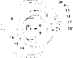
Fig. 2: the ratch reversing device is at the amplification profile of run location,
Fig. 3: the axial plane view of a reaction member of ratch reversing device,
Fig. 4: be contained in the axial plane view of the ratch spare of the ratch reversing device on Fig. 3 reaction member, and
Fig. 5-8: the various diagram details of ratch reversing device.
Yarn feeder (F) has fixing casing (G) especially for the yarn feeder (F) of knitting machine, rotatably is supported with one at its downside and press the storage yarn swift (T) that predetermined direction rotates around rotation (X) by motor (M).By means of the signal that the sniffer (D) that is installed on the casing bracing frame (1) produces, motor (M) can be activated or cut off, and the signal of generation also depends on the size that is wound up into the storage yarn (not shown) on the storage yarn swift (T).The yarn that is supplied to storage yarn swift (T) is from a (not shown) spool, and yarn passes fixing thread-carrier (2) and spider watcher (3), places at last under the supervision of the storage peripheral detection part of yarn swift (T) (5).The part that leans forward (V) of storage yarn swift (T) promotes the coil that is wound up in storage yarn swift (T) downwards, as shown in Figure 1, thereby has formed the storage yarn by many coils, and when the storage yarn is wanted the time spent, yarn will be extracted from storage yarn swift T top.
In yarn feeder (F), particularly between the top roof (6) and motor shaft (H) upper end of casing (G), a ratch reversing device (R) is arranged.Ratch reversing device (R) comprises reaction member (W) and the ratch spare (S) that is fastened among Fig. 1 embodiment on the motor shaft (H), and ratch spare rotatably places on the reaction member (W) and can rotate relatively, and by a weak helical spring (4) biasing upwards.In the embedded body (7) of roof (6), ratch spare (S) and braking surface (B) mating reaction particularly are used for stoping the return motion of storage yarn swift (T) or motor shaft (H), make their transfixions.
According to Fig. 2, reaction member (W) is an annular solid (A
1), have a wheel hub (8), be packed in the end of motor shaft (H), annular solid (A by polygon endoporus (9)
1) also having a radial flange (11) and an annular lip (14) vertically that limits spring base (12), flange (14) has a cylindrical peripheral face (15), its axis (X
1) the eccentric setting of the rotation (X) of motor shaft (H) relatively.In addition, circumferentially in the restricted portion otch (17) is arranged, formed the interface (18 and 18 ') of two circumferentially spaceds in annular lip (14).End portion in annular lip (14) forms the flange (16) that circumferentially extend on an edge.
Ratch spare (S) is enclosed within on the reaction member (W) rotationally.Ratch spare also is an annular solid (A
2), i.e. a circular disk (19), it has an endoporus (20) and a cylindrical peripheral face (21), and cylindrical peripheral face (21) cooperates with braking surface (B).In the running position that ratch reversing device (R) illustrates, the center line of outer peripheral face (21) at least with rotation (X) basically identical.The center line of endoporus (20) and axis (X
1) unanimity, and axis (X
1) be provided with respect to rotation (X) is eccentric.The receiving slit (13) of a helical spring (8) is arranged on a sharp side of circular disk (19), and groove is concentric with outer peripheral face (21).The other end of spring (4) is contained in the spring base (12) of flange (11) and compresses circular disk (19), so at least, the part surface (22) on another sharp side of circular disk is adjacent to resistance area (23), the relative casing of resistance area (G) is fixing, nose protruding (26) puts in the endoporus (20) of circular disk (19), define two interfaces (27 respectively according to Fig. 4,27 ') these two interfaces concur with other two interfaces (18 and 18 ') respectively, to form the position and the application position of running.Braking surface (B) and resistance area (23) are arranged in the embedded body (7) that is fastened on roof (6).Braking surface (B) and resistance area (23) can be set directly on the roof (6).
In this embodiment, braking surface (B) is on the brake hoop (24) that the plastic material of the material that plays rubbing action such as rubber, elastomer or other form is made, and brake hoop is tightly packed in the seat (25) of embedded body (7).In the running position shown in Fig. 2, ratch reversing device (R) does not influence the normal rotation of motor shaft (H), between outer peripheral face (21) and braking surface (B), a radial clearance (Y) is arranged.
Two annular solid (A
1, A
2) be preferably plastics forming spare, for example moulding.Inserting body (7) can be made as steel by metal material.Braking surface (B) can directly be present and be constituted on the internal perisporium of (25), also more coarse surface texture as annular knurl preferably.If necessary, outer peripheral face (21) also is equipped with the structure that increases CONTACT WITH FRICTION.
According to Fig. 4, in the running position, ratch spare (S) is installed in the position of rotation of Fig. 4 reaction member (W) annular lip (14), and reaction member itself places position of rotation shown in Figure 3.Nose protruding (26) engages with interface (27 ') on the interface (18 ').Outer peripheral face (21) then must be with rotation (X) concentric and in the face of braking surface (B), and and braking surface (B) radial clearance (Y) is arranged between (Fig. 2).The slave motor axle (H) of Fig. 3 and Fig. 4 is by reaction member (W) and ratch spare (S) rotation counterclockwise, but ratch spare does not contact with braking surface (B).Load by means of spring (8), ratch spare (S) is pressed on the resistance area (23), therefore by the CONTACT WITH FRICTION between them, a constant drag power just acts on the ratch spare (S), and this drag power keeps the composition surface (27 ') of ratch spare (S) and contacting of composition surface (18 ').
Static motor shaft (H) is just in case there is a counter-rotating (in Fig. 3,4, the direction of rotation of motor shaft is a clockwise direction), by means of with the contacting of resistance area (23), on ratch spare (S), will produce an anticlockwise resistance.Said drag power make ratch spare (S) relatively reaction member (W) go up rotation in annular lip (14), by relatively rotating, the outer peripheral face (21) of ratch spare (S) is outer to be moved and meets with braking surface (B) in the circumferential braking scope that limits and produce braking.The further return motion of motor shaft (H) has just been prevented.A composition surface (27) of nose protruding (26) arrives the composition surface (18) of annular lip (14) just.
At that time, if motor shaft (H) is driven on correct direction, promptly on the counter clockwise direction of Fig. 3 and Fig. 4, the drag power on the resistance area (23) will stop the rotation of ratch along this direction.Outer peripheral face (21) is thrown off with braking surface (B), and axis (X) will become its central axis.
This motion conversion is possible, annular solid (A
2) be fastened in the roof (6) to become in the embedded body (7), yet annular solid (A
1) around the rotation of motor shaft (H) or its end (10) (so terminal shaft must have a cylindrical axial plane), and radial clearance being arranged preferably, the sharp side (23 ') of motor shaft (H) is so as resistance area and under the effect of prestrain helical spring (4) and annular solid (A
1) sharp side (22 ') mating reaction.Or in the periphery of motor shaft (H), or at annular solid (A
1) endoporus (9) in braking surface (B) is arranged.Under a kind of in the back situation, annular solid (A
2) formed reaction member (W), and annular solid (A
1) formed ratch spare (S).
Fig. 5 simply shows the embodiment shown in Fig. 2,3 and 4.Ratch spare (S) rotatably places on reaction member (W) outside, and with braking surface (B) mating reaction of outer dress.
In Fig. 6, illustrated the principle of said motion conversion.Reaction member (W) is enclosed within ratch spare (S) periphery and be fixed (shown in cross hairs).Ratch spare (S) motor shaft (H) rotation relatively.Braking action betides respectively between the outer shaft of endoporus (9), braking surface (B) or motor shaft (H).
According to the embodiment of corresponding Fig. 7 of action principle diagram of Fig. 5 in, in the reaction braking surface zone (21 ') that the outer peripheral face (21) of ratch spare (S) is gone up an evagination of formation in the limited circumference range.Reaction braking surface (21 ') and braking surface (B) mating reaction.
In an identical manner, in embodiment corresponding to Fig. 8 of Fig. 6 action principle, in the endoporus (9) of ratch spare (S), form one in the along the circumferential direction limited scope to projecting inward reaction braking surface zone (9 '), itself and braking surface (B) mating reaction, in this case, braking surface (B) is on motor shaft (H).Reaction member (W) is one and is the convenient annular solid with polygon periphery of installing here.In Fig. 7 and 8, it is inconsistent that reaction braking surface zone (21 ', 9 ') are made into the center of the center of curvature and periphery (21 or 9) respectively.That is, the zone (21 ' or 9 ') can do to such an extent that curvature is bigger or littler, its objective is in order to guarantee special braking effect.
Ratch reversing device shown in Fig. 1 also can be set at below the motor (M).The ratch reversing device preferably can be sealed and be subjected to the influence of foul or velveteen; And these influences are inevitable when handling yarn.With the diameter of the ratch spare of braking surface (B) mating reaction preferably respectively less than storage yarn swift (T) diameter or its internal diameter.The size of the contact area between ratch spare and the resistance area (23 and 23 ') also is allowed a choice, so that under the effect of spring (4) pressure, drag power is enough guaranteed normal running, but enough low to eliminate the danger of the overheated or burning of ratch spare.
Claims (14)
1. yarn feeder, yarn feeder in particular for knitting machine, fixedly a casing and a revolving part are arranged, by means of opening of motor, close, revolving part can be driven by predetermined direction of rotation, the said revolving part that is supported in rotationally on the casing is used for yarn is wound up in the storage yarn device, be wound with many yarns on the storage yarn face of storage yarn device, want the time spent, yarn can get off from the top unwinding, and also have a cover sensing device to be used for surveying the motion change of storage yarn device periphery on the unreeling direction, and produce signal deactivation or disable motor, also have a mechanical ratch reversing device to be used for stoping the counter-rotating of revolving part, said mechanism comprises a ratch spare, it can a relative reaction member move, reaction member is between the running position and application position that docking location limited, for application position engagement at braking surface, owing to CONTACT WITH FRICTION produces a drag power, said ratch spare rotatablely moving in various rotation situations based on revolving part, said drag power, make the displacement of generation of ratch spare and reaction member irrelevant to rotation direction, consequently move to running position or application position, it is characterized in that reaction member (W) and ratch spare (S) are two annular solid (A
1, A
2), they are mutually nested and relatively rotate annular solid (A around the axis (X) of revolving part
1, A
2) zone that is bonded with each other between the two is an annular section at least, it is with respect to the eccentric setting of revolving part axis (X), with the ratch spare (S) of braking surface (B) mating reaction a reaction braking surface zone (21 ', 9 ') is arranged on its outer peripheral face (21), this zone is limited in the circumferential scope.
2. yarn feeder as claimed in claim 1 is characterized in that, forms the annular solid ((A of ratch spare (S)
1Or A
2) the sharp side pressed by spring (4) power effect, elastic force must be parallel to rotation (X) and act on resistance area (23,23 '), this resistance area is positioned on the casing or on the revolving part.
3. yarn feeder as claimed in claim 1 is characterized in that, except limiting the composition surface of running position, also has a composition surface that limits relative rotary motion between two annular solids, and it is used for limiting application position.
4. yarn feeder as claimed in claim 1, it is characterized in that, revolving part is the motor shaft (H) that is installed on casing (G) built-in motor (M), said motor shaft fixed installation storage yarn swift (T) has a ratch reversing device between facing to the enclosure wall (6) of storing yarn swift (T) and motor (M).
5. yarn feeder as claimed in claim 4 is characterized in that, forms the annular solid (A of reaction member (W)
1) be fastened on the motor shaft (H), form the annular solid (A of ratch spare (S)
2) be rotatably supported in the outside of reaction member annular solid, the outside braking surface (B) of a ratch spare (S) and a resistance area (23) that faces toward the sharp side of ratch spare (S) are arranged in enclosure wall (6).
6. as yarn feeder as described in the claim 4, it is characterized in that, form the annular solid (A of reaction member (W)
1) be packed in the enclosure wall (6), form the annular solid (A of ratch spare (S)
2) be enclosed in the reaction member annular solid braking surface (B) that ratch spare (S) is inner and all be separately positioned on the motor shaft (H) facing to the resistance area (23 ') on ratch spare (S) sharp side.
7. as yarn feeder as described in claim 5 or 6, it is characterized in that braking surface (B) is formed by brake hoop (24), brake hoop is made by friction material, said brake hoop around ratch spare (S) or by ratch spare (S) around, be equipped with a radial clearance Y at the driving position of ratch reversing device.
8. yarn feeder as claimed in claim 7 is characterized in that, the friction material of making brake hoop is selected from rubber, elastomer and plastic material.
9. yarn feeder as claimed in claim 1 is characterized in that, in the inside or the outside of ratch spare (S), a brake hoop that is made of friction material is housed.
10. yarn feeder as claimed in claim 1 is characterized in that, braking surface (B, 24,25) has the surface texture of annular knurl.
11., it is characterized in that two annular solid (A as one of claim 1 to 6 and 8 to 10 described yarn feeder
1, A
2) all be plastics forming spare.
12. yarn feeder as claimed in claim 7 is characterized in that, two annular solid (A
1, A
2) all be plastics forming spare.
13. yarn feeder as claimed in claim 4, it is characterized in that, the reaction member annular solid comprises a wheel hub (8) that is fastened on the motor shaft (H), said wheel hub (8) has an annular lip (14) vertically, annular lip has a cylindrical peripheral (15) around the eccentric setting of the rotation (X) of motor shaft (H), with the radial flange (11) that forms a spring base (12), form the interface (18 of two circumferentially spaceds at the outer peripheral face (15) of annular lip (14), 18 ') their indentation peripheries (15) or protrude from said periphery (15), ratch spare annular solid is a circular disk (19) that cylindrical peripheral face (21) and endoporus (20) are arranged, its central axis is provided with respect to the center line of outer peripheral face (21) is eccentric, its internal diameter equates with the external diameter of wheel hub (8) upper flange (14), endoporus (20) have the nose of a convex protruding respectively (26) or one is projecting member radially, and they are limited in the circumferential scope separately.
14. yarn feeder as claimed in claim 13, it is characterized in that, on circular disk (19) sharp side facing to radial flange (11), the receiving slit (13) that a dress helical spring (4) is arranged, helical spring (4) is a center line with rotation (X), spring (4) other end rests on the spring base (12) of radial flange (11) of wheel hub (8), and forms projecting member or circumferential amplifier unit (16) in the free end zone of flange (14).
Applications Claiming Priority (2)
| Application Number | Priority Date | Filing Date | Title |
|---|---|---|---|
| DE19538449.0 | 1995-10-16 | ||
| DE19538449A DE19538449A1 (en) | 1995-10-16 | 1995-10-16 | Thread delivery device |
Publications (2)
| Publication Number | Publication Date |
|---|---|
| CN1200152A CN1200152A (en) | 1998-11-25 |
| CN1065933C true CN1065933C (en) | 2001-05-16 |
Family
ID=7774958
Family Applications (1)
| Application Number | Title | Priority Date | Filing Date |
|---|---|---|---|
| CN96197658A Expired - Lifetime CN1065933C (en) | 1995-10-16 | 1996-10-10 | Thread feed device |
Country Status (7)
| Country | Link |
|---|---|
| US (1) | US6015109A (en) |
| EP (1) | EP0856074B1 (en) |
| KR (1) | KR100282545B1 (en) |
| CN (1) | CN1065933C (en) |
| DE (1) | DE59604253D1 (en) |
| ES (1) | ES2142621T3 (en) |
| TW (1) | TW475602U (en) |
Families Citing this family (5)
| Publication number | Priority date | Publication date | Assignee | Title |
|---|---|---|---|---|
| DE19840727A1 (en) * | 1998-09-07 | 2000-05-25 | Memminger Iro Gmbh | Thread delivery device for textile machines |
| DE10113184B4 (en) * | 2001-02-26 | 2006-04-20 | Memminger-Iro Gmbh | Knitting machine thread feed unit has a lever spring-operated moving end-stop |
| DE10234545B4 (en) * | 2002-07-30 | 2005-12-15 | Memminger-Iro Gmbh | Method and device for delivering threads |
| KR100734910B1 (en) * | 2005-10-25 | 2007-07-03 | 송유철 | Circular knitting machine |
| CN101768833B (en) * | 2008-12-31 | 2012-03-28 | 典洋针织机械股份有限公司 | Mechanical irregular yarn feeding device |
Citations (2)
| Publication number | Priority date | Publication date | Assignee | Title |
|---|---|---|---|---|
| US3642219A (en) * | 1969-02-26 | 1972-02-15 | Rosen Karl I J | Thread storage and delivery device for textile machines |
| DE2725185B1 (en) * | 1977-06-03 | 1978-09-28 | Iro Ab | Yarn storage and delivery device |
Family Cites Families (5)
| Publication number | Priority date | Publication date | Assignee | Title |
|---|---|---|---|---|
| US2685350A (en) * | 1950-12-21 | 1954-08-03 | Falk Corp | Reverse rotation stop |
| SE314157B (en) * | 1967-10-20 | 1969-09-01 | K Rosen | |
| DE2312508C3 (en) * | 1973-03-13 | 1975-10-16 | Ab Iro, Ulricehamn (Schweden) | Thread delivery device for the intermittent thread feed to textile machines, in particular weaving machines |
| CH623545A5 (en) * | 1977-01-17 | 1981-06-15 | Iro Ab | |
| SE511091C2 (en) * | 1993-04-21 | 1999-08-02 | Sipra Patent Beteiligung | Yarn feeder for textile machines |
-
1996
- 1996-10-10 US US09/051,066 patent/US6015109A/en not_active Expired - Fee Related
- 1996-10-10 ES ES96934622T patent/ES2142621T3/en not_active Expired - Lifetime
- 1996-10-10 CN CN96197658A patent/CN1065933C/en not_active Expired - Lifetime
- 1996-10-10 KR KR1019980702749A patent/KR100282545B1/en not_active IP Right Cessation
- 1996-10-10 EP EP96934622A patent/EP0856074B1/en not_active Expired - Lifetime
- 1996-10-10 DE DE59604253T patent/DE59604253D1/en not_active Expired - Fee Related
- 1996-10-11 TW TW088211675U patent/TW475602U/en not_active IP Right Cessation
Patent Citations (2)
| Publication number | Priority date | Publication date | Assignee | Title |
|---|---|---|---|---|
| US3642219A (en) * | 1969-02-26 | 1972-02-15 | Rosen Karl I J | Thread storage and delivery device for textile machines |
| DE2725185B1 (en) * | 1977-06-03 | 1978-09-28 | Iro Ab | Yarn storage and delivery device |
Also Published As
| Publication number | Publication date |
|---|---|
| CN1200152A (en) | 1998-11-25 |
| ES2142621T3 (en) | 2000-04-16 |
| KR100282545B1 (en) | 2001-02-15 |
| DE59604253D1 (en) | 2000-02-24 |
| EP0856074B1 (en) | 2000-01-19 |
| KR19990064260A (en) | 1999-07-26 |
| TW475602U (en) | 2002-02-01 |
| EP0856074A1 (en) | 1998-08-05 |
| US6015109A (en) | 2000-01-18 |
Similar Documents
| Publication | Publication Date | Title |
|---|---|---|
| US5449328A (en) | Tensioning device for belt or chain drives | |
| US20140117136A2 (en) | Hose Reel Rewind Speed Control | |
| CN101272937B (en) | Belt retractor | |
| EP0049897B1 (en) | Yarn braking means for yarn feeding devices | |
| CN1065933C (en) | Thread feed device | |
| KR20010021685A (en) | Electric actuator with control sensor, and disc brake comprising such actuator | |
| US5186283A (en) | Triple-wrap traction arrangement | |
| US5050814A (en) | Safety belt reeling mechanism | |
| US3944156A (en) | Thread storage and supply device | |
| US6311918B1 (en) | Device for winding and unwinding a seat belt | |
| SU613705A3 (en) | Interlocking actuator of pulling device for vehicle safety belt | |
| CN205047764U (en) | Deceleration device | |
| US3801845A (en) | Rotational characteristics sensing and signal generating mechanism and a magnetic field interrupter therefor | |
| US6168107B1 (en) | Restraining means for limiting speeds of a measuring cable returning to a linear transducer which is a cable extension transducer | |
| US5624085A (en) | Tape measure | |
| US4056239A (en) | Yarn supply apparatus for positive thread supply | |
| US4280668A (en) | Thread-storage and delivery device for textile machines | |
| US6984071B2 (en) | Instrumented antifriction bearing for control wheel | |
| KR100559328B1 (en) | Turn table device | |
| US5846124A (en) | Centrifugal abrasive grain projecting device | |
| CN100581967C (en) | Drive rollers for a textile machine producing cross-wound bobbins | |
| CN101575777B (en) | Sewing machine | |
| CA2063863A1 (en) | Device for forming a constriction on the open end zone of a metal can | |
| US5378199A (en) | Automatic retrieving structure of sliding transmission disk of motorcycle automatic transmission | |
| GB2306174A (en) | Yarn feeder |
Legal Events
| Date | Code | Title | Description |
|---|---|---|---|
| C06 | Publication | ||
| PB01 | Publication | ||
| C10 | Entry into substantive examination | ||
| SE01 | Entry into force of request for substantive examination | ||
| C14 | Grant of patent or utility model | ||
| GR01 | Patent grant | ||
| CX01 | Expiry of patent term |
Granted publication date: 20010516 |
|
| EXPY | Termination of patent right or utility model |