EP0855708B1 - Disc device - Google Patents
Disc device Download PDFInfo
- Publication number
- EP0855708B1 EP0855708B1 EP98300172A EP98300172A EP0855708B1 EP 0855708 B1 EP0855708 B1 EP 0855708B1 EP 98300172 A EP98300172 A EP 98300172A EP 98300172 A EP98300172 A EP 98300172A EP 0855708 B1 EP0855708 B1 EP 0855708B1
- Authority
- EP
- European Patent Office
- Prior art keywords
- disc
- cartridge
- control member
- moving
- single body
- Prior art date
- Legal status (The legal status is an assumption and is not a legal conclusion. Google has not performed a legal analysis and makes no representation as to the accuracy of the status listed.)
- Expired - Lifetime
Links
Images


Classifications
-
- G—PHYSICS
- G11—INFORMATION STORAGE
- G11B—INFORMATION STORAGE BASED ON RELATIVE MOVEMENT BETWEEN RECORD CARRIER AND TRANSDUCER
- G11B17/00—Guiding record carriers not specifically of filamentary or web form, or of supports therefor
- G11B17/02—Details
- G11B17/04—Feeding or guiding single record carrier to or from transducer unit
- G11B17/041—Feeding or guiding single record carrier to or from transducer unit specially adapted for discs contained within cartridges
- G11B17/043—Direct insertion, i.e. without external loading means
-
- G—PHYSICS
- G11—INFORMATION STORAGE
- G11B—INFORMATION STORAGE BASED ON RELATIVE MOVEMENT BETWEEN RECORD CARRIER AND TRANSDUCER
- G11B17/00—Guiding record carriers not specifically of filamentary or web form, or of supports therefor
-
- G—PHYSICS
- G11—INFORMATION STORAGE
- G11B—INFORMATION STORAGE BASED ON RELATIVE MOVEMENT BETWEEN RECORD CARRIER AND TRANSDUCER
- G11B17/00—Guiding record carriers not specifically of filamentary or web form, or of supports therefor
- G11B17/02—Details
- G11B17/04—Feeding or guiding single record carrier to or from transducer unit
- G11B17/05—Feeding or guiding single record carrier to or from transducer unit specially adapted for discs not contained within cartridges
- G11B17/051—Direct insertion, i.e. without external loading means
-
- G—PHYSICS
- G11—INFORMATION STORAGE
- G11B—INFORMATION STORAGE BASED ON RELATIVE MOVEMENT BETWEEN RECORD CARRIER AND TRANSDUCER
- G11B17/00—Guiding record carriers not specifically of filamentary or web form, or of supports therefor
- G11B17/02—Details
- G11B17/04—Feeding or guiding single record carrier to or from transducer unit
- G11B17/057—Feeding or guiding single record carrier to or from transducer unit specially adapted for handling both discs contained within cartridges and discs not contained within cartridges
Definitions
- the present invention relates to a disc device into which a cartridge in which a disc is accommodated or a single body disc which is not accommodated in a cartridge is inserted, and more specifically, to a disc device which permits a mechanism to be simplified and the size and thickness of the device to be reduced.
- Examples of disc devices of the prior art are a disc DA accommodated in a cartridge C as shown in FIG. 7A and a single body disc Db which is not accommodated in a cartridge as shown in FIG. 7B as a photo recording medium, a photomagentic recording medium or a phase change recording medium.
- a device provided with a tray which projects forwardly of the device, the device being arranged such that the tray is retracted into the device after the disc Db is loaded thereon and the disc Db is clamped to the turntable of a drive unit.
- transfer rollers are disposed inwardly of an inserting port, the disc Db inserted from the inserting port is retracted into the device by the rotating force of the transfer rollers, the center of the disc Db is placed on a turntable and the disc Db having been replayed is discharged from the inserting port by the transfer rollers.
- a disc device on which the cartridge C shown in FIG. 7A is to be loaded there is a disc device arranged such that the cartridge C is inserted into the device by being pushed by hand, the disc Da in the cartridge C is placed on a turntable and the cartridge C is discharged from the device by the operating force of a discharge lever which is disposed to the outside of the device and actuated by hand.
- the disc device on which the cartridge C is to be loaded there is a device arranged such that when the cartridge C is inserted, a retracting member is hooked to the cartridge C, the cartridge C is retracted into the device by the power of a motor, and when a playback or the like is finished, the cartridge C is discharged by the reverse actuating force of the retracting member.
- an operating space corresponding to the projecting distance of the tray must be provided in front of the device and a keyboard and a mouse prevents the projection of the tray in, for example, a computer. Further, since a space for accommodating the tray must be secured in the device, the size thereof is increased. Whereas, in the device in which the single body disc Db is retracted and discharged by the transfer rollers, the device is made complex by the transfer rollers and the size thereof is increased by the space occupied by the transfer rollers.
- An object of the present invention for solving the problems of the prior art is to provide a disc device into which a cartridge or a single body disc can be inserted and discharged by a simple mechanism and further can be made small and thin in size.
- Another object of the present invention is to provide a disc device which can securely position both a cartridge and a disc and securely discharge them even if the device is arranged to permit both of them to be inserted thereinto.
- the present invention provides a disc device into which both a cartridge (C) in which a disk (Da) is accommodated and a single disc (Db) which is not accommodated in a cartridge can be inserted, the device comprising a moving member (7) moved toward the inner side of the device (X1-direction) by the press force of the cartridge or the single body disc inserted from an inserting port (4); an urging member (13) for urging the moving member (7) in the direction of the inserting port (4); a turntable (23) and a clamper (5) for clamping the center of the disc in the inserted cartridge or the center of the inserted single body disc; positioning members (53,54) for positioning the cartridge or the single body disc to the turntable (23) and the clamper (5); characterized by: a control member (31) for driving the positioning members (53,54) in a positioning direction as well as driving the turntable (23) or the clamper (5) in a clamp direction by the moving force produced when the cartridge or the disc is moved in a predetermined direction
- the above disc device may comprise a spring (33) for urging the control member (31) in the predetermined direction and a locking member (44) for holding the control member (31) to the initial position against the urging force of the spring (33), wherein the control member (31) locked by the locking member (44) is released by the moving force of the cartridge or the single body disc.
- the disc device may comprise a lock release member (41) for moving the lock member (44) in a lock release direction, wherein when the moving member (7) is moved to a predetermined position on the inner side of the device, the lock release member (41) is moved in a lock releasing direction by the moving member (7), whereby the control member (31) locked by the lock member (44) is released.
- a rack (31b) is formed to the control member (31), a gear (35) driven by the restoring motor (38) is meshed with the rack (31b), and when the control member (31) is driven in the predetermined direction by the elastic force of the spring (33), the restoring motor (38) is deenergized, whereby the control member (31) is moved in the predetermined direction by the elastic force of the spring (33) without being applied with the energizing load of the restoring motor (38).
- control member (31) when the control member (31) is urged by the urging force of the spring (33) and the lock member (44) being locked is released, the control member (31) is moved in the predetermined direction by the force of the spring (33).
- the control member (31) may be moved by the push force generated when the cartridge C or the single body disc Db is inserted or by being pushed by the moving member (7) in place of the force of the spring and the positioning operation and the clamp operation of it may be carried out by the moving force of the control member (31) at the time. That is, the control member (31) is directly or indirectly driven by the inserting force of the cartridge or the single body disc or by the release of the lock executed when it is inserted.
- the turntable (23) When the disc is to be clamped, the turntable (23) may be moved in the clamp direction or the clamper (5) may be driven in the clamp direction on the contrary.
- the positioning operation or the clamp operation thereof is carried out by the operation of the control member (31) executed by the insertion and it is discharged by driving the control member (31) by the restoring motor (38). Therefore, since it suffices only to transmit the power of the motor to the control member (31), the mechanism of the disc device is simplified as well as the size thereof can be reduced and thinned. Moreover, the discharge operation can be securely carried out.
- the disc device when the disc device is arranged such that the locked control member (31) is released by the moving force of the moving member (7) to the inner side of the device and the control member (31) is moved by the spring (33), the disc device can be arranged so as to loaded with both the cartridge C and the single body disc Db. That is, since it is sufficient only to release the locked control member (31) when the cartridge C or the single body disc Db is inserted, the control member (31) can be operated even if the position of the extreme end of the cartridge C in the device when it moves to the inner side of the device is different from that of the disc Db.
- the locked control member may be directly released by the moving force of the cartridge or the single body disc. That is, the lock release member (41) may be operated by being pushed by the cartridge or the single body disc and the lock may be released by the lock member (44).
- the restoring motor (38) when the restoring motor (38) is not energized when the cartridge or the single body disc is inserted, the load when the control member (31) is operated by the force of the spring (33) can be reduced.
- FIG. 1 is an exploded perspective view showing the structure of a disc device of the present invention
- FIG. 2A is a plan view mainly showing the structure of the upper half section B of the disc device
- FIG. 2B is a side elevational view of the disc device
- FIG. 3A is a plan view mainly showing the lower half section A of the disc device
- FIG. 3B is a side elevational view of the disc device
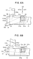
- FIG. 4 to FIG. 6 are views describing partial operations.
- the disc device can load both a cartridge C in which a disc Da is accommodated as shown in FIG. 7A and a single body disc Db which is not accommodated in a cartridge as shown in FIG. 7B on it.
- the disc Da accommodated in the cartridge C and the single body disc Db are, for example, a power disc (PD), a digital video disc, a CD-ROM and the like.
- the disc device is composed of the lower half section A and the upper half section B.
- the disc device arranged by combining the lower half section A and the upper half sect-ion B is as thin type disc device as shown in FIG. 2B and FIG. 3B.
- the disc device has a cabinet 1 which is divided into the lower cabinet 2 of the lower half section A and the upper cabinet 3 of the upper half section B.
- the combination of the lower cabinet 2 with the upper cabinet 3 results in the thin box-shaped cabinet 1 with an inserting port 4 opened on the left side in the figures as shown in FIG. 2A and FIG. 3B.
- the cartridge C shown in FIG. 7A or the disc Db shown in FIG. 7B is inserted into the cabinet 1 in an X1-direction from the inserting port 4.
- the upper cabinet 3 has a ceiling plate 3a on which a clamper 5 is rotatably supported by a shaft 5a as well as the shaft 5a and the clamper 5 are elastically pressed in the direction of the lower cabinet 2 by a leaf spring (not shown).
- a guide 6 is formed to the ceiling plate 3a of the upper cabinet 3 of the upper half section B.
- the guide 6 is formed to a slot shape and has an inclining guide portion 6a located on the inserting port 4 side which obliquely extends in the X1-direction which is the direction in which the cartridge C and the like are inserted as well as in a Y1-direction which is perpendicular to the above inserting direction and a linear guide portion 6b which is continuous to the inclining guide portion 6a and extends in the X1-direction in parallel therewith.
- a pin-shaped moving member 7 serving as a release/discharge member is inserted into the guide 6 so as to be movable in the slot of the guide 6.
- small pulleys 9a, 9b, 9c are rotatably supported on the lower surface of the ceiling plate 3a of the upper cabinet 3 and further an urging pulley 10 is rotatably supported at the corner of the upper cabinet 3 which is an end thereof in the X1-direction and in the Y1-direction.
- a wire 14 is trained around the small pulleys 9a, 9b, 9c and an urging pulley 10 so as to be caused to travel by the rotation of the urging pulley 10 by being wound around it. Then, the moving member 7 is fixed to a position of the wire 14.
- a small diameter pulley 11 is formed integrally with the urging pulley 10, an end of an urging wire 12 is fixed to the small diameter pulley 11 as well as the urging wire 12 is trained around the small diameter pulley 11.
- a discharge spring 13 as an urging member is hooked between the other end of the urging wire 12 and the upper cabinet 3.
- the urging wire 12 is pulled by the contracting force of the discharge spring 13 so that the small diameter pulley 11 and the urging pulley 10 formed integrally therewith are urged clockwise.
- the wire 14 is urged so as to travel clockwise and the moving member 7 fixed to the wire 14 is pressed against the end of the guide 6 on the inserting port 4 side thereof.
- guide members 15 are fixed on the insides of both the side plates 2b, 2b of the lower cabinet 2 which constitutes the lower half section A.
- FIG. 1 shows only the guide member 15 fixed on one of the side plates 2b.
- the guide member 15 is formed of a plastic material having a small coefficient of friction and composed of a lower guide wall 15a for supporting the lower surface of the cartridge C or the disc Db and a side guide wall 15b, which is integrally formed with the lower guide wall 15a, for guiding a side of the cartridge C or the disc Db.
- the lower guide wall 15a is located approximately at an intermediate part of the side plate 2b of the lower cabinet 2 in the height direction thereof and the cartridge C or the disc Db inserted from the inserting port 4 is guided to the upper region in the cabinet 1 by the guide member 15 as shown in FIG. 2B.
- the unit chassis 21 of a disc drive unit 20 is disposed on the bottom plate 2a of the lower cabinet 2.
- the unit chassis 21 is formed by bending a sheet material to a C-shape and provided with a thin spindle motor 22 as shown in FIG. 3B at the end thereof on the inserting port 4 side and a turntable 23 is fixed to the rotatable shaft 22a of the spindle motor 22.
- the clamper 5 disposed under the ceiling plate 3a of the upper cabinet 3 is positioned just above the turntable 23.
- an optical head 24 is supported by the unit chassis 21 so as to move in an X1 - X2 direction and provided with an objective lens 24a.
- a threat motor (not shown) is disposed on the unit chassis 21 to move the optical head 24 in the X1 - X2 direction.
- Support shafts 25 are inserted into both the side plates 21b of the unit chassis 21 on the inner side (X1-side) of the device.
- Support pieces 2c are formed to the bottom plate 2a of the lower cabinet 2 by being cut and raised therefrom and the support shafts 25 are fixed to the support pieces 2c. With this arrangement, the unit chassis 21 of the disc drive unit 20 can be turned around the support shafts 25 disposed to the inner side of the device.
- a pair of plate-shaped control members 31, 32 are disposed on the bottom plate 2a of the lower cabinet 2 and supported so as to slide in the X1 - X2 direction, respectively.
- a coil spring 33 as an urging member is hooked between one of the control members or the control member 31 and a spring hook 2d cut and raised from the bottom plate 2a of the lower cabinet 2 and the control member 31 is urged in the X2-direction by the coil spring 33.
- a coil spring 34 as an urging member is also hooked between the other control member 32 a spring hook 2e cut and raised from the bottom plate 2a of the lower cabinet 2 to thereby urge the control member 32 in the X2-direction.
- a folded piece 31a which is raised vertically is formed integrally with one of the control members or the control member 31 and a rack 31b is formed to the edge of the folded piece 31a on the X1-side thereof.
- a folded piece 32a which is raised vertically is formed to the other control member 32.
- a rack 32b is formed to the upper side end of the folded piece 32a on the X1-side thereof.
- a shaft 37 extending in the y-direction is rotatably supported at the end of the lower cabinet 2 on the X1-side thereof.
- the shaft 37 is supported by the lower cabinet 2, a mechanism for supporting it is not shown.
- a gear 35 is fixed to an end of the shaft 37 and a gear 36 is fixed to the other end thereof.
- the gear 35 is meshed with the rack 31b of one of the control members or the control member 31 and the gear 36 is meshed with the rack 32b of the other control member 32.
- the pair of control members 31, 32 are coupled with each other by the gears 35, 36 and the shaft 37 so that they move in the X1 - X2-direction in synchronism with each other.
- a restoring motor 38 is disposed to the inner side in the X1-direction of the lower cabinet 2 and the gear provided with the output shaft of the restoring motor 38 is meshed with the gear 36.
- the restoring motor 38 When the restoring motor 38 is not energized, the pair of control members 31, 32 can be moved in the X2-direction by the elastic forces of the coil springs 33, 34 regardless of the load of the restoring motor 38, whereas when the restoring motor 38 is energized, the gears 36 and 35 are driven to thereby transmit a moving force to the racks 31b and 32b so that the respective control members 31 and 32 are retracted in the X1-direction.
- a crank-shaped driving hole 31c as a driving unit is formed to the folded piece 31a of the control member 31 to drive the disc drive unit 20 in a clamp direction and a crank-shaped driving hole 32c as a driving unit is also formed to the folded piece 32a of the control member 32.
- Pins 39, 39 are fixed to both the side plates 21b, 21b of the unit chassis 21 and inserted into the driving holes 31c and 32c, respectively.
- a lock release member 41 (lock release arm) is disposed at the corner of the lower cabinet 2 on the X1-and Y1-sides.
- the lock release member 41 is rotatably supported by a support shaft 42 at the base end thereof.
- a lock spring 43 composed of a torsion spring is disposed to the outer periphery of the support shaft 42 and the lock release member 41 is urged counterclockwise by the lock spring 43 on the plan view shown in FIG. 3A (in the direction shown by a solid line a in FIG. 3A).
- An engaging groove 41a is formed to the extreme end of the lock release member 41, and when the moving member 7 which slides along the guide 6 moves to the inner portion of the device as shown in FIG. 3A, it is engaged with the engaging groove 41a.
- a folded section 41b which is folded in the direction of the bottom plate 2a is formed to the base end of the lock release member 41 and the lower end of the folded section 41b is folded in a direction parallel with the bottom plate 2a and arranged as a lock section 41c.
- a lock pin 44 as a lock member which extends in the direction of the bottom plate 2a is fixed to the extreme end of the lock section 41c.
- a hook 31d is formed to the end of the control member 31 on the X1-side thereof.
- the hook 31d is composed of a first stage hook 31d1 and a second stage hook 31d2 which is formed to an inclining side.
- the lock pin 44 is hooked to the second stage hook 31d2 as shown in FIG. 4B.
- the control member 31 is moved in the X2-direction by the elastic force of the coil spring 33 thereafter, the lock pin 44 is guided to the inclining second stage hook 31d2 and the lock release member 41 is further turned a little clockwise from the position b.
- FIG. 5 shows the state that the lock release member 41 is turned to the position c.
- a pair of positioning arms 51, 52 are disposed to both the sides in the Y1-direction and the Y2-direction of the lower cabinet 2 on the inserting port 4 side thereof.
- Positioning pins (positioning members) 53, 54 which extend upward are fixed to the extreme ends of the positioning arms 51, 52, respectively.
- the base ends of the respective positioning arms 51, 52 are rotatably supported by support shafts 55, 56 fixed to the bottom plate 2a of the lower cabinet 2.
- An associating lever 57 which extends in the Y1 - Y2 direction and is supported so as to slide in the direction is interposed between the positioning arms 51, 52.
- An associating spring 59 composed of a coil spring is interposed between the associating lever 57 and a support piece 2f cut and raised from the bottom plate 2a and the associating lever 57 is urged in the Y2-direction by the associating spring 59.
- a square hole 47a is formed to the end of the associating lever 57 on the Y1-side thereof and the support shaft 55 which supports the base end of the positioning arm 51 is positioned in the square hole 57a.
- a rack 57b is formed to the edge of the square hole 57a on the X2-side thereof and a gear 51a which is fixed to the base end of the positioning arm 51 integrally therewith around the support arm 55 is meshed with the rack 57b.
- a square hole 57c is also formed to the end of the associating lever 57 on the Y2-side thereof and the support shaft 56 which supports the base end of the positioning arm 52 is positioned in the square hole 57c.
- a rack 57d is formed to the edge of the square hole 57c on the X1-side thereof which is opposite to the square hole 57a.
- a gear 52a is fixed to the base portion of the positioning arm 51 integrally therewith around the support shaft 56 and meshed with the rack 57d.
- the positioning arm 51 is turned counterclockwise and the positioning arm 52 is turned clockwise by the mesh of the rack 57b with the gear 51a and the mesh of the rack 57d with the gear 52a, so that the positioning pin 53 and the positioning pin 54 are separated from each other.
- the positioning arm 52 is turned clockwise and the positioning arm 52 is turned counterclockwise, so that the positioning pin 53 and the positioning pin 54 approach each other.
- a regulating section 57e is formed to the edge of the associating lever 57 on the Y1-side thereof.
- the regulating section 57e is composed of a V-shaped valley portion 57e1, an inclining portion 57e2 and a linear portion 57e3 extending in the X1 - X2 direction.
- a regulating ping 58 which extends toward the bottom plate 2a is provided with the end of the control member 31 on the X2-side thereof and can be engaged with the regulating section 57e.
- FIG. 6A shows the state that the control member 31 moves most in the X1-direction and at the time the regulating ping 58 is engaged with the valley portion 57e1 of the regulating section 57e and the associating lever 57 moves in the Y1-direction and is held there.
- the positioning arms 51, 52 turns to a position d.
- the regulating ping 58 slides along the inclining portion 57e2 and reaches the boundary to the linear portion 57e3.
- the associating lever 57 is moved in the Y2-direction by the urging force of the associating spring 59.
- the positioning arms 51, 52 turns to a position e.
- the disc device can be loaded with both the cartridge C in which the disc Da is accommodated as shown in FIG. 7A and the single body disc Db as shown in FIG. 7B.
- the discs Da and Db have the same diameter and same inside diameter of the center hole D1 thereof.
- the cartridge C shown in FIG. 7A includes a shutter S at the end thereof on the X1-side which is an inserting direction and the shutter S can slide in the Y-direction and is urged in a closing direction (Y2-direction) by a spring.
- a window is opened to the cartridge C and the center hole D1 and the disc surface of a disc D appear from the window.
- the moving member 7 disposed to the upper cabinet 3 is located at a position shown by g at the end of the guide 6 on the X2-side.
- An urging force in the X2-direction is applied to the moving member 7 by the elastic force of the discharge spring 13.
- both the control members 31 and 32 move in the X1-direction in an initial state.
- the lock release member 41 is turned to an attitude a by being urged counterclockwise by the lock spring 43.
- the lock pin 44 disposed to the base end of the lock release member 41 is hooked to the first stage hook 31d1 of the hook 31d formed to the control member 31 and locked to a position to which the control member 31 moved in the X1-direction.
- the regulating ping 58 disposed to the end of the control member 31 on the X2-side is engaged with the valley portion 57e1 of the regulating section 57e formed to the associating lever 57 and the associating lever 57 is held at a position to which it was retracted in the Y1-direction against the tension of the associating spring 59.
- the positioning arm 51 is turned counterclockwise by the rack 57b disposed to the associating lever 57 on the Y1-side and the positioning arm 52 is turned clockwise by the rack 57d disposed to the associating lever 57 on the Y2-side, so that both the positioning arms 51, 52 are located at the position d and the respective positioning pins 53, 54 are separated from each other.
- the positioning pins 53, 54 do not prevent the insertion of the disc Db or the cartridge C.
- the disc device is arranged as a manual slot-in system in which the disc Db or the cartridge C is inserted from the inserting port 4 in the X1-direction by being manually pushed by the operator without energizing the restoring motor 38 at the time of insertion.
- the disc Db is inserted from the inserting port 4 into the cabinet 1 and introduced onto the lower guide walls 15a of the guide members 15 disposed to both the side plates 2b, 2b of the lower cabinet 2.
- the extreme end thereof is abutted against the moving member 7 located at the position g.
- the moving member 7 is pushed by the edge in the X1-direction of the disc Db and the moving member 7 is moved in the X1-direction while sliding along the guide 6 in accordance with the insertion of the disc Db.
- the wire 14 travels counterclockwise to thereby turn the urging pulley 10 counterclockwise, so that the urging wire 12 is wound around the small diameter pulley 11 formed integrally with the urging pulley 10 and the discharge spring 13 is extended.
- the moving member 7 When the moving member 7 is pushed up to a position h shown in FIG. 3A by the edge in the X1-direction of the disc Db, the moving member 7 begins to enter the engaging groove 41a of the lock release member 41 located at the position a.
- the centering operation and clamping operation of the disc Db are continuously carried out while the disc Db is pushed in the above state and the moving member 7 moves up to a position i.
- the positioning arm 51 is turned clockwise by the rack 57b and the positioning arm 52 is turned counterclockwise by the rack 57d, so that both the positioning arms 51, 52 are moved from the position d to the position e.
- the disc Db When both the positioning arms 51, 52 are turned in the direction e, the disc Db is retracted in the X1-direction by the force resulting from the approach of the positioning pins 53, 54 fixed to the respective positioning arms 51, 52 to each other. Then, as shown in FIG. 2A, the disc Db is centered by three points, that is, the positioning pins 53, 54 at the position e and the moving member 7 at the position i and the center hole D1 of the disc Db approximately coincides with the centers of the turntable 23 and the clamper 5.
- the pins 39, 39 are lifted by the respective crank shapes of the driving hole 31c of the control member 31 moved in the X2-direction and the driving hole 32c of the control member 32 and the unit chassis 21 is turned upward around the support shafts 25, 25. Then, approximately simultaneously with or just after the completion of the centering of the disc Db, the center hole D1 of the disc Db is clamped between the turntable 23 and the clamper 5.
- the disc Db is centered by the positioning pins 53, 54 and the moving member 7 and the clamped between the turntable 23 and the clamper 5.
- the control member 31 has been further moved a short distance by the tension of the coil spring 33 in the X2-direction at the time shown in FIG. 4B at which the centering and the clamp are finished.
- the lock release member 41 is a little turned clockwise from the position b by the inclining second stage hook 31d2 of the hook 31d. With this operation, the moving member 7 held to the engaging groove 41a of the lock release member 41 a little moves in the X1-direction and leaves from the clamped disc Db.
- the moving member 7 located at the position g in FIG. 2A is engaged with the end S1 of the shutter S.
- the moving member 7 is moved along the guide 6 by being pushed.
- the shutter S is slid in the Y1-direction by the moving component of force of the moving member 7 in the Y1- direction.
- the moving member 7 reaches the inflection point 6c from the inclining guide portion 6a of the guide 6 to the linear guide portion 6b thereof, the shutter S is completely opened. Thereafter, when the cartridge C is pushed, the moving member 7 slides along the linear guide portion 6b of the guide 6 in the X1-direction.
- the regulating ping 58 disposed to the end of the control member 31 on the X2-side is removed from the valley portion 57e1 of the regulating section 57e of the associating lever 57 and the associating lever 57 is moved in the Y2-direction by the urging force of the associating spring 59. Therefore, the positioning arm 51 is turned clockwise by the rack 57b disposed to the associating lever 57 and the positioning arm 52 turned counterclockwise by the rack 57d, so that the positioning pins 53, 54 are abutted against both the sides of the cartridge C. At the time, the positioning pins 53, 54 are elastically pressed against the cartridge C by the elastic force of the associating spring 59.
- the positioning arms 51, 52 are turned to a position f and the positioning pins 53, 54 are engaged with the recesses C1, C1 of both the sides of the cartridge C to thereby position and hold the cartridge C.
- the shutter S has been opened by the moving member 7 when the cartridge C is position and held as described above, and the center hole D1 of the disk Da which is exposed by opening the shutter S is clamped between the turntable 23 and the clamper 5. Then, replay operation is carried out by the optical head 24.
- the disc Db or the cartridge C is inserted by hand in the disc device as described above, its discharge operation is carried out by the power of the restoring motor 38.
- the positioning arm 51 is turned counterclockwise and the positioning arm 52 is turned clockwise, so that the positioning pins 53, 54 are separated from the disc Db or the cartridge C to thereby release the disc Db or the cartridge C which has been positioned and held. Further, the unit chassis 21 is lowered by the driving holes 31c and 32c, so that the disc clamped by the turntable 23 and the clamper 5 is released.
- the disc Db or the cartridge C is pushed out from the inserting port 4 by the urging force in the X2- direction of the moving member 7 resulting from the elastic tension of the discharge spring 13 shown in FIG. 2A.
- the lock release member 41 is turned counterclockwise.
- the control member 31 is returned in the X1-direction before the lock release member 41 is turned to the position a, the lock pin 44 at the base of the lock release member 41 turned to the position a is engaged with the first stage hook 31d1 as shown in FIG. 4A, the control member 31 moves in the X1-direction and is locked at an initial position and the restoring motor 38 is stopped at the time.
- the moving member 7 is returned to the position g and the shutter S is closed accordingly.
- the cartridge or the single body disc when the cartridge or the single body disc is inserted, it is positioned or held by the operation of the control member executed in accordance with the insertion, whereas, when the cartridge or the single body disc is discharged, the control member is operated by the restoring motor. Therefore, the mechanism of the disc device is simplified because it suffices only to apply the power of the restoring motor to the control member.
- the operation of the control member can be stated by releasing the lock by any of the cartridge and the disc.
Applications Claiming Priority (3)
| Application Number | Priority Date | Filing Date | Title |
|---|---|---|---|
| JP00992997A JP3699230B2 (ja) | 1997-01-23 | 1997-01-23 | ディスク装置 |
| JP992997 | 1997-01-23 | ||
| JP9929/97 | 1997-01-23 |
Publications (2)
| Publication Number | Publication Date |
|---|---|
| EP0855708A1 EP0855708A1 (en) | 1998-07-29 |
| EP0855708B1 true EP0855708B1 (en) | 2002-05-02 |
Family
ID=11733767
Family Applications (1)
| Application Number | Title | Priority Date | Filing Date |
|---|---|---|---|
| EP98300172A Expired - Lifetime EP0855708B1 (en) | 1997-01-23 | 1998-01-12 | Disc device |
Country Status (5)
| Country | Link |
|---|---|
| EP (1) | EP0855708B1 (ja) |
| JP (1) | JP3699230B2 (ja) |
| KR (1) | KR100258497B1 (ja) |
| DE (1) | DE69805109T2 (ja) |
| TW (1) | TW382121B (ja) |
Families Citing this family (1)
| Publication number | Priority date | Publication date | Assignee | Title |
|---|---|---|---|---|
| US6504808B2 (en) | 1998-10-08 | 2003-01-07 | Pioneer Corporation | Front-loading disk player with separate first and second carrier units |
Family Cites Families (8)
| Publication number | Priority date | Publication date | Assignee | Title |
|---|---|---|---|---|
| CA1204859A (en) * | 1982-12-12 | 1986-05-20 | Nobuyuki Hara | Loading apparatus for a disc |
| BE902262A (fr) * | 1985-04-23 | 1985-08-16 | Staar Sa | Dispositif de chargement automatique de disques dans un tourne-disques. |
| DE3643779A1 (de) * | 1986-12-20 | 1988-07-07 | Philips Patentverwaltung | Geraet zum aufnehmen und/oder wiedergeben von signalen auf informationsplatten mit einem lichtoptischen einschreibe- und/oder ausleseaggregat (auto-cd-spieler) |
| JPH0520759A (ja) * | 1991-04-19 | 1993-01-29 | Sony Corp | デイスクドライブ装置 |
| JP2897457B2 (ja) * | 1991-06-10 | 1999-05-31 | ソニー株式会社 | ディスクプレーヤ |
| JP3107453B2 (ja) * | 1992-04-27 | 2000-11-06 | 日本コロムビア株式会社 | Md検知機構、mdシャッター開閉機構およびそれらを用いたcd/md両用ディスクプレーヤー |
| JP3106874B2 (ja) * | 1993-09-29 | 2000-11-06 | 松下電器産業株式会社 | 円盤記録再生装置 |
| JPH0855449A (ja) * | 1994-08-11 | 1996-02-27 | Sony Corp | ディスクドライブ装置 |
-
1997
- 1997-01-23 JP JP00992997A patent/JP3699230B2/ja not_active Expired - Fee Related
- 1997-12-19 TW TW086119357A patent/TW382121B/zh not_active IP Right Cessation
- 1997-12-30 KR KR1019970078927A patent/KR100258497B1/ko not_active IP Right Cessation
-
1998
- 1998-01-12 DE DE69805109T patent/DE69805109T2/de not_active Expired - Fee Related
- 1998-01-12 EP EP98300172A patent/EP0855708B1/en not_active Expired - Lifetime
Also Published As
| Publication number | Publication date |
|---|---|
| JP3699230B2 (ja) | 2005-09-28 |
| EP0855708A1 (en) | 1998-07-29 |
| TW382121B (en) | 2000-02-11 |
| KR100258497B1 (ko) | 2000-07-01 |
| JPH10208348A (ja) | 1998-08-07 |
| KR19980070282A (ko) | 1998-10-26 |
| DE69805109D1 (de) | 2002-06-06 |
| DE69805109T2 (de) | 2002-08-22 |
Similar Documents
| Publication | Publication Date | Title |
|---|---|---|
| JPH0677047U (ja) | ディスク装置 | |
| JP3890660B2 (ja) | ディスク記録及び/又は再生装置 | |
| EP0855708B1 (en) | Disc device | |
| JPH11162068A (ja) | ディスク装置 | |
| JP3956395B2 (ja) | ディスクカートリッジのローディング装置 | |
| EP0855707B1 (en) | Disk device | |
| JPH06111449A (ja) | ディスク記録装置 | |
| JP3694381B2 (ja) | ディスク装置 | |
| JP2900665B2 (ja) | ディスクローディング装置 | |
| JP3098176B2 (ja) | 光ディスク装置とそのディスク交換方法 | |
| JP2988044B2 (ja) | ディスク駆動装置のディスクローディング機構 | |
| JP3890659B2 (ja) | ディスク記録及び/又は再生装置 | |
| JP3114638B2 (ja) | ディスク装置 | |
| JP3090576B2 (ja) | ディスクチェンジャー装置 | |
| JP3457486B2 (ja) | ディスクチェンジャー | |
| JPH07240076A (ja) | ディスクプレーヤ装置 | |
| JP3091695B2 (ja) | コンパクトディスクプレーヤ | |
| JP2865490B2 (ja) | コンパクトディスクプレーヤ | |
| JP3449914B2 (ja) | ディスクチェンジャー | |
| JP3449916B2 (ja) | ディスク演奏装置 | |
| JPH09128865A (ja) | 記録再生装置 | |
| JPH07240075A (ja) | ディスクプレーヤ装置 | |
| JPH07240061A (ja) | ディスク収納装置 | |
| JPH04360061A (ja) | ディスクチェンジャー装置 | |
| JPS63179459A (ja) | デイスククランプ装置 |
Legal Events
| Date | Code | Title | Description |
|---|---|---|---|
| PUAI | Public reference made under article 153(3) epc to a published international application that has entered the european phase |
Free format text: ORIGINAL CODE: 0009012 |
|
| AK | Designated contracting states |
Kind code of ref document: A1 Designated state(s): DE FR GB NL |
|
| AX | Request for extension of the european patent |
Free format text: AL;LT;LV;MK;RO;SI |
|
| 17P | Request for examination filed |
Effective date: 19980716 |
|
| AKX | Designation fees paid |
Free format text: DE FR GB NL |
|
| RBV | Designated contracting states (corrected) |
Designated state(s): DE FR GB NL |
|
| 17Q | First examination report despatched |
Effective date: 19991229 |
|
| GRAG | Despatch of communication of intention to grant |
Free format text: ORIGINAL CODE: EPIDOS AGRA |
|
| GRAG | Despatch of communication of intention to grant |
Free format text: ORIGINAL CODE: EPIDOS AGRA |
|
| GRAH | Despatch of communication of intention to grant a patent |
Free format text: ORIGINAL CODE: EPIDOS IGRA |
|
| GRAH | Despatch of communication of intention to grant a patent |
Free format text: ORIGINAL CODE: EPIDOS IGRA |
|
| REG | Reference to a national code |
Ref country code: GB Ref legal event code: IF02 |
|
| GRAA | (expected) grant |
Free format text: ORIGINAL CODE: 0009210 |
|
| AK | Designated contracting states |
Kind code of ref document: B1 Designated state(s): DE FR GB NL |
|
| REG | Reference to a national code |
Ref country code: GB Ref legal event code: FG4D |
|
| REF | Corresponds to: |
Ref document number: 69805109 Country of ref document: DE Date of ref document: 20020606 |
|
| REG | Reference to a national code |
Ref country code: FR Ref legal event code: RN |
|
| EN | Fr: translation not filed | ||
| REG | Reference to a national code |
Ref country code: FR Ref legal event code: FC |
|
| PLBE | No opposition filed within time limit |
Free format text: ORIGINAL CODE: 0009261 |
|
| STAA | Information on the status of an ep patent application or granted ep patent |
Free format text: STATUS: NO OPPOSITION FILED WITHIN TIME LIMIT |
|
| ET | Fr: translation filed | ||
| 26N | No opposition filed |
Effective date: 20030204 |
|
| PGFP | Annual fee paid to national office [announced via postgrant information from national office to epo] |
Ref country code: GB Payment date: 20041217 Year of fee payment: 8 |
|
| PGFP | Annual fee paid to national office [announced via postgrant information from national office to epo] |
Ref country code: NL Payment date: 20050117 Year of fee payment: 8 |
|
| PGFP | Annual fee paid to national office [announced via postgrant information from national office to epo] |
Ref country code: FR Payment date: 20050125 Year of fee payment: 8 |
|
| PGFP | Annual fee paid to national office [announced via postgrant information from national office to epo] |
Ref country code: DE Payment date: 20050318 Year of fee payment: 8 |
|
| PG25 | Lapsed in a contracting state [announced via postgrant information from national office to epo] |
Ref country code: GB Free format text: LAPSE BECAUSE OF NON-PAYMENT OF DUE FEES Effective date: 20060112 |
|
| PG25 | Lapsed in a contracting state [announced via postgrant information from national office to epo] |
Ref country code: FR Free format text: LAPSE BECAUSE OF NON-PAYMENT OF DUE FEES Effective date: 20060131 |
|
| PG25 | Lapsed in a contracting state [announced via postgrant information from national office to epo] |
Ref country code: NL Free format text: LAPSE BECAUSE OF NON-PAYMENT OF DUE FEES Effective date: 20060801 Ref country code: DE Free format text: LAPSE BECAUSE OF NON-PAYMENT OF DUE FEES Effective date: 20060801 |
|
| GBPC | Gb: european patent ceased through non-payment of renewal fee |
Effective date: 20060112 |
|
| NLV4 | Nl: lapsed or anulled due to non-payment of the annual fee |
Effective date: 20060801 |
|
| REG | Reference to a national code |
Ref country code: FR Ref legal event code: ST Effective date: 20060929 |