EP0853172A2 - Sonnenschutzanlage - Google Patents
Sonnenschutzanlage Download PDFInfo
- Publication number
- EP0853172A2 EP0853172A2 EP97123025A EP97123025A EP0853172A2 EP 0853172 A2 EP0853172 A2 EP 0853172A2 EP 97123025 A EP97123025 A EP 97123025A EP 97123025 A EP97123025 A EP 97123025A EP 0853172 A2 EP0853172 A2 EP 0853172A2
- Authority
- EP
- European Patent Office
- Prior art keywords
- longitudinal
- tension
- rails
- guide rails
- longitudinal guide
- Prior art date
- Legal status (The legal status is an assumption and is not a legal conclusion. Google has not performed a legal analysis and makes no representation as to the accuracy of the status listed.)
- Granted
Links
Images

Classifications
-
- E—FIXED CONSTRUCTIONS
- E04—BUILDING
- E04F—FINISHING WORK ON BUILDINGS, e.g. STAIRS, FLOORS
- E04F10/00—Sunshades, e.g. Florentine blinds or jalousies; Outside screens; Awnings or baldachins
- E04F10/02—Sunshades, e.g. Florentine blinds or jalousies; Outside screens; Awnings or baldachins of flexible canopy materials, e.g. canvas ; Baldachins
- E04F10/06—Sunshades, e.g. Florentine blinds or jalousies; Outside screens; Awnings or baldachins of flexible canopy materials, e.g. canvas ; Baldachins comprising a roller-blind with means for holding the end away from a building
- E04F10/0607—Sunshades, e.g. Florentine blinds or jalousies; Outside screens; Awnings or baldachins of flexible canopy materials, e.g. canvas ; Baldachins comprising a roller-blind with means for holding the end away from a building with guiding-sections for supporting the movable end of the blind
-
- E—FIXED CONSTRUCTIONS
- E04—BUILDING
- E04F—FINISHING WORK ON BUILDINGS, e.g. STAIRS, FLOORS
- E04F10/00—Sunshades, e.g. Florentine blinds or jalousies; Outside screens; Awnings or baldachins
- E04F10/02—Sunshades, e.g. Florentine blinds or jalousies; Outside screens; Awnings or baldachins of flexible canopy materials, e.g. canvas ; Baldachins
- E04F10/06—Sunshades, e.g. Florentine blinds or jalousies; Outside screens; Awnings or baldachins of flexible canopy materials, e.g. canvas ; Baldachins comprising a roller-blind with means for holding the end away from a building
- E04F10/0644—Sunshades, e.g. Florentine blinds or jalousies; Outside screens; Awnings or baldachins of flexible canopy materials, e.g. canvas ; Baldachins comprising a roller-blind with means for holding the end away from a building with mechanisms for unrolling or balancing the blind
- E04F10/0655—Sunshades, e.g. Florentine blinds or jalousies; Outside screens; Awnings or baldachins of flexible canopy materials, e.g. canvas ; Baldachins comprising a roller-blind with means for holding the end away from a building with mechanisms for unrolling or balancing the blind acting on the movable end, e.g. front bar
-
- E—FIXED CONSTRUCTIONS
- E04—BUILDING
- E04F—FINISHING WORK ON BUILDINGS, e.g. STAIRS, FLOORS
- E04F10/00—Sunshades, e.g. Florentine blinds or jalousies; Outside screens; Awnings or baldachins
- E04F10/02—Sunshades, e.g. Florentine blinds or jalousies; Outside screens; Awnings or baldachins of flexible canopy materials, e.g. canvas ; Baldachins
- E04F10/06—Sunshades, e.g. Florentine blinds or jalousies; Outside screens; Awnings or baldachins of flexible canopy materials, e.g. canvas ; Baldachins comprising a roller-blind with means for holding the end away from a building
- E04F10/0666—Accessories
- E04F10/067—Accessories acting as intermediate support of the flexible canopy
Definitions
- the invention relates to a sun protection system, in particular for conservatories with top horizontal or sloping roof glazing and adjoining vertical wall glazing, with an upper one Cloth shaft, one attached to the front end of the cloth web, in the side the transition edge of the glazed longitudinal guide rails guided drop bar, as well as with a tensioning device with tension or compression springs parallel to the longitudinal rails, by means of cable pulls, via deflection rollers are guided, tension the drop bar in the drop direction.
- the invention is therefore based on the object of a sun protection system type mentioned so that with a simplified structure safe and clean extension of the fabric web is possible with the drop bar, without deflecting cables over the entire length of the longitudinal guide rails be used.
- the invention provides that the train or Compression springs in longitudinal clamping rails along the horizontal or inclined Upper cover surfaces are arranged, the cables with one to the drop bar parallel tension rod guided in the longitudinal tensioning rails are, which engages behind the drop bar to this in the longitudinal guide rails to the knee area in the transition to the essentially vertical Moving wall glazing.
- the tension rod can - if the longitudinal guide rails are formed separately and the clamping longitudinal rails - at least at one end with the drop bar interlocking coupling fingers be provided, so that in the two Longitudinal rails over one another sliding rods can be coupled together can.
- the invention is based on the finding that spring support for the drop movement of the drop bar only in the oblique or horizontal upper Area of glazing is required, but in the vertical area Wall glazing the drop bar then falling vertically downwards alone due to its predeterminable weight, it is sufficient to hold the awning cover when unwinding the fabric shaft, as well as if necessary wind pressure or the like. catch springy. Accordingly, only horizontal or sloping area of the roof glazing with the help of the spring-assisted Failure forces exerted on the drop bar. Once the drop bar but gets into the knee area, where it is essentially in the vertical longitudinal guide rails hanging freely down and thus their entire weight acts on the cloth, is this supportive force not necessary anymore.
- the tension rod has its end position in this knee area reached and can no longer follow the movement of the drop bar, which is free by pulling the sheet of fabric down to the lower end of the longitudinal guide rails the wall glazing can fall down.
- the tension or compression springs take along and so these tension or compression springs again tensions so that when unwinding the cloth web in the above described Way can take effect.
- the longitudinal clamping rails can be on the corresponding upper legs the longitudinal guide rails are attached or, if necessary, also in one piece to them be molded on.
- the tension rod in the longitudinal guide rails immediately behind the extension bar is guided and at the same time the cloth deflection rail in the knee area forms.
- this version one does without separate one above the other arranged longitudinal guide rails and longitudinal clamping rails. This does the system is structurally simpler and more delicate due to the lack of double guides and more elegant and in particular you save the separate cloth deflection rail.
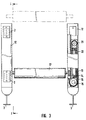
- the sun protection system comprises in the embodiment 1 to 3 angled longitudinal guide rails 1 with a sloping, possibly also horizontal upper leg 1a in the area of the roof glazing and a substantially vertical bar 1b in the area of the wall glazing.
- Two such longitudinal guide rails 1 are at a distance of the width of one Cloth web spaced using spacers 2 and 3 under the roof or attached to the wall inside. They are with C-shaped undercut grooves 4 (cf. in particular Fig. 2) provided for receiving guide rollers 5 on the Serve axes 6 of a drop rod 7.
- On the drop bar 7 is the front one free end of a sheet of cloth 8 serving as sun protection shading attached, which can be unwound from a cloth shaft 8a.
- the two spaced in parallel Guide rails for one sheet of fabric 8 each - with intermediate rails on both sides be equipped with guides for two adjoining sheets of cloth can - are in the area of the knee 9, i.e. the bend between the oblique Leg 1a and the vertical leg 1b, with side cheeks 10 for fastening a cloth deflecting rail offset parallel to the connecting axis of the apex 9 11 provided.
- the cloth web not shown in FIG. 1, lies above this 8 if the drop bar is somewhere in the area of the vertical leg 1b is on.
- each longitudinal guide rail 1 - if necessary, such a support facility is sufficient one side of - clamping longitudinal rails 12 placed, one designed as a gas spring Compression spring 13 included.
- the end 14 of this compression spring 13 is rigid in the longitudinal clamping rail 12 attached, in the area of a fixed deflection roller 15, over which a tension cable 16 is guided and in a manner not shown a tie rod 17 parallel to the drop rod 7 is connected.
- This is in similar to the drop bar with the help of guide rollers 18 in a C-shape Guide grooves 19 of the longitudinal clamping rails 12 out.
- To the Tension rods 17 are preferably attached to both sides of coupling fingers 20, which loosely reach behind the extension rod 7 in order to prevent the tension rod from moving 17 to move the drop bar 7 forward.
- the cable 16 guided over the deflection roller 15 to the tension rod 17 is via a second inner deflection roller 21 deflected at the movable inner end of the Gas spring, in the illustrated embodiment the free end of the piston 22, is attached.
- the cable 16 is preferably multiple pulley-like deflected, since the stroke length of the gas spring 13 never the total length of the Longitudinal clamping rail 12 can correspond.
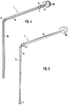
- the tension rod 17 is of those which are otherwise similar to the embodiment according to FIGS. 1 to 3 trained tension spring moved in the same guide profile, in which too the drop bar 7 runs.
- the tension rod 17 presses directly from behind onto the drop bar 7 and move it to the area of the knee 9.
- the end of the displacement path of the tension rod 17 ends due to the design the springs and the arrangement of the pulleys is fixed.
- the drop bar 7 falls in the vertical section as described above 1b of the longitudinal guide rail 1 downward and thereby pulls the cloth web 8 after her.
- the embodiment according to the Figures 4 and 5 is so much simpler in construction than that according to FIGS. 1 to 3, the embodiment according to FIGS. 1 to 3 has the advantage that you can convert existing systems by the Longitudinal clamping rails 12 with the gas springs arranged therein simply above on the slightly inclined or horizontal sections 1a of the longitudinal guide rails existing systems builds on the failure behavior of the drop bar 7 to improve in this flat area.
Landscapes
- Engineering & Computer Science (AREA)
- Architecture (AREA)
- Civil Engineering (AREA)
- Structural Engineering (AREA)
- Building Awnings And Sunshades (AREA)
- Train Traffic Observation, Control, And Security (AREA)
- Absorbent Articles And Supports Therefor (AREA)
- Curtains And Furnishings For Windows Or Doors (AREA)
- Blinds (AREA)
- Operating, Guiding And Securing Of Roll- Type Closing Members (AREA)
- Tents Or Canopies (AREA)
Abstract
Description
- Fig. 1
- einen vertikalen Längsschnitt durch eine erfindungsgemäße Sonnenschutzanlage für Innenbeschattung längs der Linie I-I in Fig. 3,
- Fig. 2
- einen vergrößerten Schnitt längs der Linie II-II in Fig. 1,
- Fig. 3
- eine Draufsicht auf die Sonnenschutzanlage nach Fig. 1 und 2, und
- Fig.4 und 5
- dem vertikalen Längsschnitt der Fig. 1 entsprechende stark schematisierte Längsschnitte durch eine Zweite Ausführungsform, bei der gesondere Spann-Längsschienen nicht vorgesehen sind und die Spannstange unmittelbar hinter der Ausfallstange in den Führungs-Längsschienen verschoben wird.
Claims (6)
- Sonnenschutzanlage, insbesondere für Wintergärten mit oberen waagrecht oder schräg geneigt verlaufenden Dachverglasungen und anstoßenden senkrechten Wandverglasungen, mit einer oberen Tuchwelle, einer am vorderen Ende der Tuchbahn befestigten, in seitlichen, an der Übergangskante der Verglasungen abgewinkelten Führungs-Längsschienen geführten Ausfallstange, sowie mit einer Spannvorrichtung mit Zug- oder Druckfedern parallel zu den Längsschienen, die mittels Seilzügen, die über Umlenkrollen geführt sind, die Ausfallstange in Ausfallrichtung spannen, dadurch gekennzeichnet, daß die Zug- oder Druckfedern (13) in Spann-Längsschienen (12) entlang der waagrechten oder schrägen oberen Abdeckflächen angeordnet sind, wobei die Seilzüge (16) mit einer zur Ausfallstange (7) parallelen, in den Spann-Längsschienen (12) geführten Spannstange (17) verbunden sind, die die Ausfallstange hintergreift, um diese in den waagrechten oder schrägen Schenkeln (1a) der Führungs-Längsschienen (1) bis in den Bereich des Knies (9) im Übergang zur im wesentlichen vertikalen Wandverglasung zu verschieben.
- Sonnenschutzanlage nach Anspruch 1, dadurch gekennzeichnet, daß die Spannstange zumindest am einen Ende mit einem die Ausfallstange (7) hintergreifenden Koppelfinger (20) versehen ist.
- Sonnenschutzanlage nach Anspruch 1 oder 2, dadurch gekennzeichnet, daß die Spann-Längsschienen (12) auf die Führungs-Längsschienen (1) aufgesetzt sind.
- Sonnenschutzanlage nach einem der Ansprüche 1 bis 3, dadurch gekennzeichnet, daß die Spann-Längsschienen (12) einstückig an den waagrechten oder schrägen Schenkeln (1a) der Führungs-Längsschinene (12) angeformt sind.
- Sonnenschutzanlage nach einem der Ansprüche 1 bis 3, dadurch gekennzeichnet, daß die Führungs-Längsschienen (1) im Kniebereich mit Seitenwangen (10) für eine zur Verbindungsachse parallel versetzte Tuchumlenkschiene (11) versehen sind.
- Sonnenschutzanlage nach Anspruch 1, dadurch gekennzeichnet, daß die Spannstange in den Führungs-Längsschienen unmittelbar hinter der Ausfallstange geführt ist und gleichzeitig die Tuchumlenkschiene im Kniebereich bildet.
Applications Claiming Priority (2)
| Application Number | Priority Date | Filing Date | Title |
|---|---|---|---|
| DE19700757 | 1997-01-11 | ||
| DE19700757A DE19700757C2 (de) | 1997-01-11 | 1997-01-11 | Gegenzugmarkise |
Publications (3)
| Publication Number | Publication Date |
|---|---|
| EP0853172A2 true EP0853172A2 (de) | 1998-07-15 |
| EP0853172A3 EP0853172A3 (de) | 2000-01-05 |
| EP0853172B1 EP0853172B1 (de) | 2004-11-10 |
Family
ID=7817182
Family Applications (1)
| Application Number | Title | Priority Date | Filing Date |
|---|---|---|---|
| EP97123025A Expired - Lifetime EP0853172B1 (de) | 1997-01-11 | 1997-12-31 | Sonnenschutzanlage |
Country Status (3)
| Country | Link |
|---|---|
| EP (1) | EP0853172B1 (de) |
| AT (1) | ATE282121T1 (de) |
| DE (2) | DE19700757C2 (de) |
Cited By (1)
| Publication number | Priority date | Publication date | Assignee | Title |
|---|---|---|---|---|
| WO2007087659A1 (de) * | 2006-02-01 | 2007-08-09 | Plaspack Netze Gmbh | Spannvorrichtung für ein von einer wickelwelle abziehbares sonnensegel |
Families Citing this family (1)
| Publication number | Priority date | Publication date | Assignee | Title |
|---|---|---|---|---|
| DE10150693A1 (de) * | 2001-10-17 | 2003-05-08 | Clauss Markisen | Gegenzugmarkise mit Führungsrollen mit Rillen |
Family Cites Families (4)
| Publication number | Priority date | Publication date | Assignee | Title |
|---|---|---|---|---|
| DE8524022U1 (de) * | 1985-08-22 | 1986-08-21 | Weinor Dieter Weiermann GmbH & Co, 5000 Köln | Abdeckvorrichtung |
| DE4139312A1 (de) * | 1991-11-29 | 1993-06-03 | Weiermann Dieter Weinor | Abdeckvorrichtung |
| US5186231A (en) * | 1992-05-01 | 1993-02-16 | Milburn Lewis | Tarpaulin deployment and retraction apparatus |
| DE9311755U1 (de) * | 1993-08-06 | 1993-10-07 | Warema Renkhoff Gmbh, 97828 Marktheidenfeld | Sonnenschutzanlage mit im oberen Bereich flach geneigten Führungsschienen |
-
1997
- 1997-01-11 DE DE19700757A patent/DE19700757C2/de not_active Expired - Fee Related
- 1997-12-31 DE DE59712071T patent/DE59712071D1/de not_active Expired - Fee Related
- 1997-12-31 EP EP97123025A patent/EP0853172B1/de not_active Expired - Lifetime
- 1997-12-31 AT AT97123025T patent/ATE282121T1/de not_active IP Right Cessation
Cited By (2)
| Publication number | Priority date | Publication date | Assignee | Title |
|---|---|---|---|---|
| WO2007087659A1 (de) * | 2006-02-01 | 2007-08-09 | Plaspack Netze Gmbh | Spannvorrichtung für ein von einer wickelwelle abziehbares sonnensegel |
| AT503120B1 (de) * | 2006-02-01 | 2007-08-15 | Plaspack Netze Gmbh | Spannvorrichtung für ein von einer wickelwelle abziehbares sonnensegel |
Also Published As
| Publication number | Publication date |
|---|---|
| ATE282121T1 (de) | 2004-11-15 |
| EP0853172A3 (de) | 2000-01-05 |
| EP0853172B1 (de) | 2004-11-10 |
| DE59712071D1 (de) | 2004-12-16 |
| DE19700757A1 (de) | 1998-07-23 |
| DE19700757C2 (de) | 2000-09-14 |
Similar Documents
| Publication | Publication Date | Title |
|---|---|---|
| EP0539788B1 (de) | Führungsstab für Fensterdekorationen oder Beschattungssysteme | |
| EP0519241B1 (de) | Zugvorrichtung vorzugsweise zum Ein- und Ausziehen eines Tuches für eine Store, sowie dazugehörige Store | |
| DE69202677T2 (de) | Motorisiertes Fensterrolle für gebogenes Fenster. | |
| DE19717654C2 (de) | Markisenhalterung | |
| DE3841139C2 (de) | Sonnenschutzanlage für flächige Glasabdeckungen, insbesondere Wintergartendächer | |
| DE3344359A1 (de) | Fenstermarkise | |
| DE4402964B4 (de) | Gelenkarmmarkise | |
| EP0853172B1 (de) | Sonnenschutzanlage | |
| DE9403006U1 (de) | Sonnenschutzvorrichtung | |
| DE3324170A1 (de) | Markisolette mit ausfallarmen | |
| DE10316785B4 (de) | Rollovorrichtung | |
| DE3624740A1 (de) | Markise | |
| DE19814577C1 (de) | Sonnenschutzanlage | |
| DE102004022352B4 (de) | Markise | |
| DE29801334U1 (de) | Rolladensicherung | |
| DE102019006789A1 (de) | Beschattungsvorrichtung | |
| DE2501478C3 (de) | Bewegliche Trennwand | |
| DE3151778C2 (de) | Fahrzeugschiebedach | |
| DE19510431C1 (de) | Schnurloser Raffvorhang | |
| CH686794A5 (de) | Store. | |
| DE3410283A1 (de) | Rollmarkise | |
| DE3302853C2 (de) | Markise mit abgeknickten Führungsschienen | |
| DE10063454B4 (de) | Vorrichtung zum Verschließen und/oder Beschatten eines Öffnungsquerschnitts bzw. einer Fläche | |
| EP1099808B1 (de) | Markise | |
| EP3933163A1 (de) | Anordnung zu einer gelenkigen verbindung eines rollpanzers eines rollladens mit einer rollladenwelle und rollladen mit einer solchen anordnung |
Legal Events
| Date | Code | Title | Description |
|---|---|---|---|
| PUAI | Public reference made under article 153(3) epc to a published international application that has entered the european phase |
Free format text: ORIGINAL CODE: 0009012 |
|
| AK | Designated contracting states |
Kind code of ref document: A2 Designated state(s): AT BE CH DE DK ES FR GB GR IT LI NL |
|
| AX | Request for extension of the european patent |
Free format text: AL;LT;LV;MK;RO;SI |
|
| PUAL | Search report despatched |
Free format text: ORIGINAL CODE: 0009013 |
|
| AK | Designated contracting states |
Kind code of ref document: A3 Designated state(s): AT BE CH DE DK ES FI FR GB GR IE IT LI LU MC NL PT SE |
|
| AX | Request for extension of the european patent |
Free format text: AL;LT;LV;MK;RO;SI |
|
| 17P | Request for examination filed |
Effective date: 20000126 |
|
| AKX | Designation fees paid |
Free format text: AT BE CH DE DK ES FR GB GR IT LI NL |
|
| 17Q | First examination report despatched |
Effective date: 20030424 |
|
| GRAP | Despatch of communication of intention to grant a patent |
Free format text: ORIGINAL CODE: EPIDOSNIGR1 |
|
| GRAS | Grant fee paid |
Free format text: ORIGINAL CODE: EPIDOSNIGR3 |
|
| GRAA | (expected) grant |
Free format text: ORIGINAL CODE: 0009210 |
|
| AK | Designated contracting states |
Kind code of ref document: B1 Designated state(s): AT BE CH DE DK ES FR GB GR IT LI NL |
|
| PG25 | Lapsed in a contracting state [announced via postgrant information from national office to epo] |
Ref country code: IT Free format text: LAPSE BECAUSE OF FAILURE TO SUBMIT A TRANSLATION OF THE DESCRIPTION OR TO PAY THE FEE WITHIN THE PRESCRIBED TIME-LIMIT;WARNING: LAPSES OF ITALIAN PATENTS WITH EFFECTIVE DATE BEFORE 2007 MAY HAVE OCCURRED AT ANY TIME BEFORE 2007. THE CORRECT EFFECTIVE DATE MAY BE DIFFERENT FROM THE ONE RECORDED. Effective date: 20041110 Ref country code: FR Free format text: LAPSE BECAUSE OF NON-PAYMENT OF DUE FEES Effective date: 20041110 |
|
| REG | Reference to a national code |
Ref country code: GB Ref legal event code: FG4D Free format text: NOT ENGLISH |
|
| REG | Reference to a national code |
Ref country code: CH Ref legal event code: NV Representative=s name: SCHMAUDER & PARTNER AG PATENTANWALTSBUERO Ref country code: CH Ref legal event code: EP |
|
| GBT | Gb: translation of ep patent filed (gb section 77(6)(a)/1977) |
Effective date: 20041110 |
|
| PGFP | Annual fee paid to national office [announced via postgrant information from national office to epo] |
Ref country code: NL Payment date: 20041205 Year of fee payment: 8 |
|
| PGFP | Annual fee paid to national office [announced via postgrant information from national office to epo] |
Ref country code: AT Payment date: 20041213 Year of fee payment: 8 |
|
| REF | Corresponds to: |
Ref document number: 59712071 Country of ref document: DE Date of ref document: 20041216 Kind code of ref document: P |
|
| PGFP | Annual fee paid to national office [announced via postgrant information from national office to epo] |
Ref country code: GB Payment date: 20041229 Year of fee payment: 8 Ref country code: CH Payment date: 20041229 Year of fee payment: 8 |
|
| PG25 | Lapsed in a contracting state [announced via postgrant information from national office to epo] |
Ref country code: BE Free format text: LAPSE BECAUSE OF NON-PAYMENT OF DUE FEES Effective date: 20041231 |
|
| PG25 | Lapsed in a contracting state [announced via postgrant information from national office to epo] |
Ref country code: GR Free format text: LAPSE BECAUSE OF FAILURE TO SUBMIT A TRANSLATION OF THE DESCRIPTION OR TO PAY THE FEE WITHIN THE PRESCRIBED TIME-LIMIT Effective date: 20050210 Ref country code: DK Free format text: LAPSE BECAUSE OF FAILURE TO SUBMIT A TRANSLATION OF THE DESCRIPTION OR TO PAY THE FEE WITHIN THE PRESCRIBED TIME-LIMIT Effective date: 20050210 |
|
| PG25 | Lapsed in a contracting state [announced via postgrant information from national office to epo] |
Ref country code: ES Free format text: LAPSE BECAUSE OF FAILURE TO SUBMIT A TRANSLATION OF THE DESCRIPTION OR TO PAY THE FEE WITHIN THE PRESCRIBED TIME-LIMIT Effective date: 20050221 |
|
| BERE | Be: lapsed |
Owner name: WEINOR, DIE MARKISE, DIETER WEIERMANN G.M.B.H. & C Effective date: 20041231 |
|
| PLBE | No opposition filed within time limit |
Free format text: ORIGINAL CODE: 0009261 |
|
| STAA | Information on the status of an ep patent application or granted ep patent |
Free format text: STATUS: NO OPPOSITION FILED WITHIN TIME LIMIT |
|
| 26N | No opposition filed |
Effective date: 20050811 |
|
| EN | Fr: translation not filed | ||
| PG25 | Lapsed in a contracting state [announced via postgrant information from national office to epo] |
Ref country code: LI Free format text: LAPSE BECAUSE OF NON-PAYMENT OF DUE FEES Effective date: 20051231 Ref country code: GB Free format text: LAPSE BECAUSE OF NON-PAYMENT OF DUE FEES Effective date: 20051231 Ref country code: CH Free format text: LAPSE BECAUSE OF NON-PAYMENT OF DUE FEES Effective date: 20051231 Ref country code: AT Free format text: LAPSE BECAUSE OF NON-PAYMENT OF DUE FEES Effective date: 20051231 |
|
| EN | Fr: translation not filed | ||
| PG25 | Lapsed in a contracting state [announced via postgrant information from national office to epo] |
Ref country code: NL Free format text: LAPSE BECAUSE OF NON-PAYMENT OF DUE FEES Effective date: 20060701 |
|
| REG | Reference to a national code |
Ref country code: CH Ref legal event code: PL |
|
| GBPC | Gb: european patent ceased through non-payment of renewal fee |
Effective date: 20051231 |
|
| NLV4 | Nl: lapsed or anulled due to non-payment of the annual fee |
Effective date: 20060701 |
|
| BERE | Be: lapsed |
Owner name: *WEINOR DIE MARKISE DIETER WEIERMANN G.M.B.H. & CO Effective date: 20041231 |
|
| PGFP | Annual fee paid to national office [announced via postgrant information from national office to epo] |
Ref country code: DE Payment date: 20081229 Year of fee payment: 12 |
|
| PG25 | Lapsed in a contracting state [announced via postgrant information from national office to epo] |
Ref country code: DE Free format text: LAPSE BECAUSE OF NON-PAYMENT OF DUE FEES Effective date: 20100701 |