EP0853172A2 - Sun protecting arrangement - Google Patents
Sun protecting arrangement Download PDFInfo
- Publication number
- EP0853172A2 EP0853172A2 EP97123025A EP97123025A EP0853172A2 EP 0853172 A2 EP0853172 A2 EP 0853172A2 EP 97123025 A EP97123025 A EP 97123025A EP 97123025 A EP97123025 A EP 97123025A EP 0853172 A2 EP0853172 A2 EP 0853172A2
- Authority
- EP
- European Patent Office
- Prior art keywords
- longitudinal
- rails
- tension
- drop
- longitudinal guide
- Prior art date
- Legal status (The legal status is an assumption and is not a legal conclusion. Google has not performed a legal analysis and makes no representation as to the accuracy of the status listed.)
- Granted
Links
Images

Classifications
-
- E—FIXED CONSTRUCTIONS
- E04—BUILDING
- E04F—FINISHING WORK ON BUILDINGS, e.g. STAIRS, FLOORS
- E04F10/00—Sunshades, e.g. Florentine blinds or jalousies; Outside screens; Awnings or baldachins
- E04F10/02—Sunshades, e.g. Florentine blinds or jalousies; Outside screens; Awnings or baldachins of flexible canopy materials, e.g. canvas ; Baldachins
- E04F10/06—Sunshades, e.g. Florentine blinds or jalousies; Outside screens; Awnings or baldachins of flexible canopy materials, e.g. canvas ; Baldachins comprising a roller-blind with means for holding the end away from a building
- E04F10/0607—Sunshades, e.g. Florentine blinds or jalousies; Outside screens; Awnings or baldachins of flexible canopy materials, e.g. canvas ; Baldachins comprising a roller-blind with means for holding the end away from a building with guiding-sections for supporting the movable end of the blind
-
- E—FIXED CONSTRUCTIONS
- E04—BUILDING
- E04F—FINISHING WORK ON BUILDINGS, e.g. STAIRS, FLOORS
- E04F10/00—Sunshades, e.g. Florentine blinds or jalousies; Outside screens; Awnings or baldachins
- E04F10/02—Sunshades, e.g. Florentine blinds or jalousies; Outside screens; Awnings or baldachins of flexible canopy materials, e.g. canvas ; Baldachins
- E04F10/06—Sunshades, e.g. Florentine blinds or jalousies; Outside screens; Awnings or baldachins of flexible canopy materials, e.g. canvas ; Baldachins comprising a roller-blind with means for holding the end away from a building
- E04F10/0644—Sunshades, e.g. Florentine blinds or jalousies; Outside screens; Awnings or baldachins of flexible canopy materials, e.g. canvas ; Baldachins comprising a roller-blind with means for holding the end away from a building with mechanisms for unrolling or balancing the blind
- E04F10/0655—Sunshades, e.g. Florentine blinds or jalousies; Outside screens; Awnings or baldachins of flexible canopy materials, e.g. canvas ; Baldachins comprising a roller-blind with means for holding the end away from a building with mechanisms for unrolling or balancing the blind acting on the movable end, e.g. front bar
-
- E—FIXED CONSTRUCTIONS
- E04—BUILDING
- E04F—FINISHING WORK ON BUILDINGS, e.g. STAIRS, FLOORS
- E04F10/00—Sunshades, e.g. Florentine blinds or jalousies; Outside screens; Awnings or baldachins
- E04F10/02—Sunshades, e.g. Florentine blinds or jalousies; Outside screens; Awnings or baldachins of flexible canopy materials, e.g. canvas ; Baldachins
- E04F10/06—Sunshades, e.g. Florentine blinds or jalousies; Outside screens; Awnings or baldachins of flexible canopy materials, e.g. canvas ; Baldachins comprising a roller-blind with means for holding the end away from a building
- E04F10/0666—Accessories
- E04F10/067—Accessories acting as intermediate support of the flexible canopy
Definitions
- the invention relates to a sun protection system, in particular for conservatories with top horizontal or sloping roof glazing and adjoining vertical wall glazing, with an upper one Cloth shaft, one attached to the front end of the cloth web, in the side the transition edge of the glazed longitudinal guide rails guided drop bar, as well as with a tensioning device with tension or compression springs parallel to the longitudinal rails, by means of cable pulls, via deflection rollers are guided, tension the drop bar in the drop direction.
- the invention is therefore based on the object of a sun protection system type mentioned so that with a simplified structure safe and clean extension of the fabric web is possible with the drop bar, without deflecting cables over the entire length of the longitudinal guide rails be used.
- the invention provides that the train or Compression springs in longitudinal clamping rails along the horizontal or inclined Upper cover surfaces are arranged, the cables with one to the drop bar parallel tension rod guided in the longitudinal tensioning rails are, which engages behind the drop bar to this in the longitudinal guide rails to the knee area in the transition to the essentially vertical Moving wall glazing.
- the tension rod can - if the longitudinal guide rails are formed separately and the clamping longitudinal rails - at least at one end with the drop bar interlocking coupling fingers be provided, so that in the two Longitudinal rails over one another sliding rods can be coupled together can.
- the invention is based on the finding that spring support for the drop movement of the drop bar only in the oblique or horizontal upper Area of glazing is required, but in the vertical area Wall glazing the drop bar then falling vertically downwards alone due to its predeterminable weight, it is sufficient to hold the awning cover when unwinding the fabric shaft, as well as if necessary wind pressure or the like. catch springy. Accordingly, only horizontal or sloping area of the roof glazing with the help of the spring-assisted Failure forces exerted on the drop bar. Once the drop bar but gets into the knee area, where it is essentially in the vertical longitudinal guide rails hanging freely down and thus their entire weight acts on the cloth, is this supportive force not necessary anymore.
- the tension rod has its end position in this knee area reached and can no longer follow the movement of the drop bar, which is free by pulling the sheet of fabric down to the lower end of the longitudinal guide rails the wall glazing can fall down.
- the tension or compression springs take along and so these tension or compression springs again tensions so that when unwinding the cloth web in the above described Way can take effect.
- the longitudinal clamping rails can be on the corresponding upper legs the longitudinal guide rails are attached or, if necessary, also in one piece to them be molded on.
- the tension rod in the longitudinal guide rails immediately behind the extension bar is guided and at the same time the cloth deflection rail in the knee area forms.
- this version one does without separate one above the other arranged longitudinal guide rails and longitudinal clamping rails. This does the system is structurally simpler and more delicate due to the lack of double guides and more elegant and in particular you save the separate cloth deflection rail.
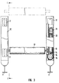
- the sun protection system comprises in the embodiment 1 to 3 angled longitudinal guide rails 1 with a sloping, possibly also horizontal upper leg 1a in the area of the roof glazing and a substantially vertical bar 1b in the area of the wall glazing.
- Two such longitudinal guide rails 1 are at a distance of the width of one Cloth web spaced using spacers 2 and 3 under the roof or attached to the wall inside. They are with C-shaped undercut grooves 4 (cf. in particular Fig. 2) provided for receiving guide rollers 5 on the Serve axes 6 of a drop rod 7.
- On the drop bar 7 is the front one free end of a sheet of cloth 8 serving as sun protection shading attached, which can be unwound from a cloth shaft 8a.
- the two spaced in parallel Guide rails for one sheet of fabric 8 each - with intermediate rails on both sides be equipped with guides for two adjoining sheets of cloth can - are in the area of the knee 9, i.e. the bend between the oblique Leg 1a and the vertical leg 1b, with side cheeks 10 for fastening a cloth deflecting rail offset parallel to the connecting axis of the apex 9 11 provided.
- the cloth web not shown in FIG. 1, lies above this 8 if the drop bar is somewhere in the area of the vertical leg 1b is on.
- each longitudinal guide rail 1 - if necessary, such a support facility is sufficient one side of - clamping longitudinal rails 12 placed, one designed as a gas spring Compression spring 13 included.
- the end 14 of this compression spring 13 is rigid in the longitudinal clamping rail 12 attached, in the area of a fixed deflection roller 15, over which a tension cable 16 is guided and in a manner not shown a tie rod 17 parallel to the drop rod 7 is connected.
- This is in similar to the drop bar with the help of guide rollers 18 in a C-shape Guide grooves 19 of the longitudinal clamping rails 12 out.
- To the Tension rods 17 are preferably attached to both sides of coupling fingers 20, which loosely reach behind the extension rod 7 in order to prevent the tension rod from moving 17 to move the drop bar 7 forward.
- the cable 16 guided over the deflection roller 15 to the tension rod 17 is via a second inner deflection roller 21 deflected at the movable inner end of the Gas spring, in the illustrated embodiment the free end of the piston 22, is attached.
- the cable 16 is preferably multiple pulley-like deflected, since the stroke length of the gas spring 13 never the total length of the Longitudinal clamping rail 12 can correspond.
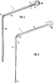
- the tension rod 17 is of those which are otherwise similar to the embodiment according to FIGS. 1 to 3 trained tension spring moved in the same guide profile, in which too the drop bar 7 runs.
- the tension rod 17 presses directly from behind onto the drop bar 7 and move it to the area of the knee 9.
- the end of the displacement path of the tension rod 17 ends due to the design the springs and the arrangement of the pulleys is fixed.
- the drop bar 7 falls in the vertical section as described above 1b of the longitudinal guide rail 1 downward and thereby pulls the cloth web 8 after her.
- the embodiment according to the Figures 4 and 5 is so much simpler in construction than that according to FIGS. 1 to 3, the embodiment according to FIGS. 1 to 3 has the advantage that you can convert existing systems by the Longitudinal clamping rails 12 with the gas springs arranged therein simply above on the slightly inclined or horizontal sections 1a of the longitudinal guide rails existing systems builds on the failure behavior of the drop bar 7 to improve in this flat area.
Landscapes
- Engineering & Computer Science (AREA)
- Architecture (AREA)
- Civil Engineering (AREA)
- Structural Engineering (AREA)
- Building Awnings And Sunshades (AREA)
- Operating, Guiding And Securing Of Roll- Type Closing Members (AREA)
- Tents Or Canopies (AREA)
- Train Traffic Observation, Control, And Security (AREA)
- Absorbent Articles And Supports Therefor (AREA)
- Blinds (AREA)
- Curtains And Furnishings For Windows Or Doors (AREA)
Abstract
Description
Die Erfindung bezieht sich auf eine Sonnenschutzanlage, insbesondere für Wintergärten mit oberen waagrecht oder schräg geneigt verlaufenden Dachverglasungen und anstoßenden senkrechten Wandverglasungen, mit einer oberen Tuchwelle, einer am vorderen Ende der Tuchbahn befestigten, in seitlichen, an der Übergangskante der Verglasungen abgewinkelten Führungs-Längsschienen geführten Ausfallstange, sowie mit einer Spannvorrichtung mit Zug- oder Druckfedern parallel zu den Längschienen, die mittels Seilzügen, die über Umlenkrollen geführt sind, die Ausfallstange in Ausfallrichtung spannen.The invention relates to a sun protection system, in particular for conservatories with top horizontal or sloping roof glazing and adjoining vertical wall glazing, with an upper one Cloth shaft, one attached to the front end of the cloth web, in the side the transition edge of the glazed longitudinal guide rails guided drop bar, as well as with a tensioning device with tension or compression springs parallel to the longitudinal rails, by means of cable pulls, via deflection rollers are guided, tension the drop bar in the drop direction.
Bei allen derartigen Sonnenschutzanlagen, man vergleiche hierzu beispielsweise die EP 0 545 062 B1, ist vorgesehen, daß jeweils eine Umlenkrolle an dem der Tuchwelle am weitesten abgelegenen Ende der Führungs-Längsschienen angeordnet ist, wodurch die Führungseinrichtungen sehr kompliziert und störanfällig werden. Es ergeben sich meterlange Seilzüge, bei denen die Gefahr eines Verklemmens einer funktionsbeeinträchtigenden Längung im Betrieb und bei unterschiedlichen Temperaturen sowie die Gefahr des Auftretens unerwünschter Geräusche an den Umlenkstellen und Umlenkrollen besonders störend sind.With all such sun protection systems, compare for example EP 0 545 062 B1, it is provided that a deflecting roller on each of the The fabric shaft is arranged at the most distant end of the longitudinal guide rails is, which makes the management devices very complicated and prone to failure will. There are meter-long cables with which there is a risk of jamming a functionally impairing elongation in operation and with different Temperatures and the risk of unwanted noise are particularly annoying at the deflection points and deflection rollers.
Der Erfindung liegt daher die Aufgabe zugrunde, eine Sonnenschutzanlage der eingangs genannten Art so auszugestalten, daß bei vereinfachtem Aufbau ein sicheres und sauberes Ausfahren der Tuchbahn mit der Ausfallstange möglich ist, ohne daß Umlenkseilzüge über die gesamte Länge der Führungs-Längsschienen eingesetzt werden.The invention is therefore based on the object of a sun protection system type mentioned so that with a simplified structure safe and clean extension of the fabric web is possible with the drop bar, without deflecting cables over the entire length of the longitudinal guide rails be used.
Zur Lösung dieser Aufgabe ist erfindungsgemäß vorgesehen, daß die Zug- oder Druckfedern in Spann-Längsschienen entlang der waagrechten oder schrägen oberen Abdeckflächen angeordnet sind, wobei die Seilzüge mit einer zur Ausfallstange parallelen, in den Spann-Längsschienen geführten Spannstange verbunden sind, die die Ausfallstange hintergreift, um diese in den Führungs-Längsschienen bis in den Kniebereich im Übergang zur im wesentlichen vertikalen Wandverglasung zu verschieben. To solve this problem, the invention provides that the train or Compression springs in longitudinal clamping rails along the horizontal or inclined Upper cover surfaces are arranged, the cables with one to the drop bar parallel tension rod guided in the longitudinal tensioning rails are, which engages behind the drop bar to this in the longitudinal guide rails to the knee area in the transition to the essentially vertical Moving wall glazing.
Die Spannstange kann - bei getrennter Ausbildung der Führungs-Längsschienen und der Spann-Längsschienen - zumindest am einen Ende mit einem die Ausfallstange hintergreifenden Koppelfinger versehen sein, damit die in den beiden Längsschienen übereinander gleitenden Stangen miteinander gekoppelt sein können.The tension rod can - if the longitudinal guide rails are formed separately and the clamping longitudinal rails - at least at one end with the drop bar interlocking coupling fingers be provided, so that in the two Longitudinal rails over one another sliding rods can be coupled together can.
Der Erfindung liegt dabei die Erkenntnis zugrunde, daß eine Federunterstützung für die Ausfallbewegung der Ausfallstange nur im schrägen oder horizontalen oberen Bereich der Verglasung erforderlich ist, daß aber im Bereich der vertikalen Wandverglasung die dann senkrecht nach unten fallende Ausfallstange allein durch ihr entsprechend vorgebbares Gewicht sowohl ausreicht, um das Markisentuch beim Abwickeln der Tuchwelle gespannt nachzuziehen, als auch ggf. Winddruck od.dgl. federnd abzufangen. Demzufolge werden nur im horizontalen oder schräg geneigten Bereich der Dachverglasung mit Hilfe der federunterstützten Spannvorrichtung Ausfallkräfte auf die Ausfallstange ausgeübt. Sobald die Ausfallstange aber in den Kniebereich gelangt, in dem sie in den im wesentlichen senkrecht nach unten gerichteten Führungs-Längsschienen frei herunterhängt und somit ihr gesamtes Gewicht auf das Tuch wirkt, ist diese Unterstützungskraft nicht mehr erforderlich. Die Spannstange hat in diesem Kniebereich ihre Endposition erreicht und kann der Bewegung der Ausfallstange nicht mehr folgen, die frei unter Nachziehen der Tuchbahn bis zum unteren Ende der Längs-Führungsschienen der Wandverglasung herunterfallen kann. Beim Wiederaufwickeln der Tuchwelle wird die Ausfallstange frei hochgezogen, bis sie wiederum an den Koppelfingern der Spannstange anstößt und dann diese entgegen der Kraft der Zug- oder Druckfedern mitnimmt und so diese Zug- oder Druckfedern wieder spannt, so daß sie beim Wiederabwickeln der Tuchbahn in der vorstehend beschriebenen Weise wirksam werden können.The invention is based on the finding that spring support for the drop movement of the drop bar only in the oblique or horizontal upper Area of glazing is required, but in the vertical area Wall glazing the drop bar then falling vertically downwards alone due to its predeterminable weight, it is sufficient to hold the awning cover when unwinding the fabric shaft, as well as if necessary wind pressure or the like. catch springy. Accordingly, only horizontal or sloping area of the roof glazing with the help of the spring-assisted Failure forces exerted on the drop bar. Once the drop bar but gets into the knee area, where it is essentially in the vertical longitudinal guide rails hanging freely down and thus their entire weight acts on the cloth, is this supportive force not necessary anymore. The tension rod has its end position in this knee area reached and can no longer follow the movement of the drop bar, which is free by pulling the sheet of fabric down to the lower end of the longitudinal guide rails the wall glazing can fall down. When rewinding the drop bar is pulled up freely until it turns on the coupling fingers of the tension rod and then this against the force the tension or compression springs take along and so these tension or compression springs again tensions so that when unwinding the cloth web in the above described Way can take effect.
Die Spann-Längsschienen können dabei auf die entsprechenden oberen Schenkel der Führungs-Längsschienen aufgesteckt oder ggf. auch einstückig an diesen angeformt sein. The longitudinal clamping rails can be on the corresponding upper legs the longitudinal guide rails are attached or, if necessary, also in one piece to them be molded on.
Schließlich liegt es auch noch im Rahmen der Erfindung, daß die Führungs-Längsschienen im Kniebereich mit Seitenwangen für eine zur Verbindungsachse parallel versetzte Tuchumlenkschiene versehen sind.Finally, it is also within the scope of the invention that the longitudinal guide rails in the knee area with side cheeks for one to the connection axis parallel fabric deflection rail are provided.
Die Versetzung der Tuchumlenkschiene gegenüber der Verbindungsachse der Kniescheitel beruht darauf, daß ja die Ausfallstange an dieser Stelle passieren muß und demzufolge die Tuchumlenkstange entsprechend zurückgesetzt sein muß.The offset of the cloth deflection rail relative to the connecting axis of the The part of the knee is based on the fact that the drop bar passes through at this point and therefore the cloth deflecting rod must be reset accordingly got to.
Gemäß einer besonders vorteilhaften Weiterbildung der Erfindung kann vorgesehen sein, daß die Spannstange in den Führungs-Längsschienen unmittelbar hinter der Ausfallstange geführt ist und gleichzeitig die Tuchumlenkschiene im Kniebereich bildet. Bei dieser Ausführung verzichtet man also auf getrennte übereinander angeordnete Führungs-Längsschienen und Spann-Längsschienen. Dies macht die Anlage baulich einfacher und wegen der fehlenden Doppelführungen zierlicher und eleganter und man spart insbesondere auch die gesonderte Tuchumlenkschiene. Die hinter der Ausfallstange in den Führungs-Längsschienen über die Gasfedern nach vorne gedrückte Spannstange nimmt die Ausfallstange bis in den Kniebereich mit, in dem sie dann aufgrund ihres Gewichts frei nach unten fällt und bleibt ihrerseits - dies ergibt sich automatisch durch die entsprechende Auslegung der Gasfedern - im Kniebereich stehen, so daß sie dann in dieser ausgefahrenen Position die Funktion der Tuchumlenkschiene gleich mit übernehmen kann.According to a particularly advantageous development of the invention can be provided be that the tension rod in the longitudinal guide rails immediately behind the extension bar is guided and at the same time the cloth deflection rail in the knee area forms. In this version, one does without separate one above the other arranged longitudinal guide rails and longitudinal clamping rails. This does the system is structurally simpler and more delicate due to the lack of double guides and more elegant and in particular you save the separate cloth deflection rail. The behind the drop bar in the longitudinal guide rails over the The tension rod, which is pushed forward by gas springs, takes the extension rod into the Knee area in which it then falls freely due to its weight and remains in turn - this automatically results from the appropriate interpretation the gas springs - stand in the knee area, so that they are then extended Position can also take over the function of the fabric deflection rail.
Weitere Vorteile, Merkmale und Einzelheiten der Erfindung ergeben sich aus der nachfolgenden Beschreibung eines Ausführungsbeispiels sowie anhand der Zeichnung. Dabei zeigen:
- Fig. 1
- einen vertikalen Längsschnitt durch eine erfindungsgemäße Sonnenschutzanlage für Innenbeschattung längs der Linie I-I in Fig. 3,
- Fig. 2
- einen vergrößerten Schnitt längs der Linie II-II in Fig. 1,
- Fig. 3
- eine Draufsicht auf die Sonnenschutzanlage nach Fig. 1 und 2, und
- Fig.4 und 5
- dem vertikalen Längsschnitt der Fig. 1 entsprechende stark schematisierte Längsschnitte durch eine Zweite Ausführungsform, bei der gesondere Spann-Längsschienen nicht vorgesehen sind und die Spannstange unmittelbar hinter der Ausfallstange in den Führungs-Längsschienen verschoben wird.
- Fig. 1
- 3 shows a vertical longitudinal section through a sun protection system according to the invention for internal shading along the line II in FIG. 3,
- Fig. 2
- 2 shows an enlarged section along the line II-II in FIG. 1,
- Fig. 3
- a plan view of the sun protection system according to FIGS. 1 and 2, and
- Fig. 4 and 5
- 1 shows a highly schematic longitudinal section corresponding to the vertical longitudinal section of FIG. 1, in which special longitudinal clamping rails are not provided and the clamping rod is shifted directly behind the extension rod in the longitudinal guide rails.
Die erfindungsgemäße Sonnenschutzanlage umfaßt beim Ausführungsbeispiel
nach den Figuren 1 bis 3 abgewinkelte Führungs-Längsschienen 1 mit einem
schrägen, ggf. auch horizontalen oberen Schenkel 1a im Bereich der Dachverglasung
und einen im wesentlichen vertikalen Schenke 1b im Bereich der Wandverglasung.
Zwei solche Führungs-Längsschienen 1 sind im Abstand der Breite einer
Tuchbahn beabstandet mit Hilfe der Abstandhalter 2 und 3 unter dem Dach bzw.
an der Wand innen befestigt. Sie sind mit C-förmig hinterschnittenen Nuten 4 (vgl.
insbesondere Fig. 2) versehen, die zur Aufnahme von Führungsrollen 5 auf den
Achsen 6 einer Ausfallstange 7 dienen. An der Ausfallstange 7 ist das vordere
freie Ende einer als Sonnenschutzabschattung dienenden Tuchbahn 8 befestigt,
die von einer Tuchwelle 8a abwickelbar ist. Die beiden parallel beabstandeten
Führungsschienen für jeweils eine Tuchbahn 8 - wobei Zwischenschienen beidseits
mit Führungen für zwei aneinanderstoßende Tuchbahnen ausgestattet sein
können - sind im Bereich des Knies 9, also der Abwinklung zwischen dem schrägen
Schenkel 1a und dem vertikalen Schenkel 1b, mit Seitenwangen 10 zum Befestigen
einer zur Verbindungsachse der Scheitel 9 parallel versetzten Tuchumlenkschiene
11 versehen. Über dieser liegt die in der Figur 1 nicht gezeigte Tuchbahn
8, wenn die Ausfallstange sich irgendwo im Bereich des vertikalen Schenkels
1b befindet, auf.The sun protection system according to the invention comprises in the
Erfindungsgemäß sind auf den schrägen Schenkel 1a jeder Führungs-Längsschiene
1 - ggf. reicht auch eine solche Unterstützungseinrichtung auf nur
einer Seite aus - Spann-Längsschienen 12 aufgesetzt, die eine als Gasfeder ausgebildete
Druckfeder 13 enthalten. Das Ende 14 dieser Druckfeder 13 ist starr in
der Spann-Längsschiene 12 befestigt, und zwar im Bereich einer festen Umlenkrolle
15, über die ein Spannseil 16 geführt und in nicht gezeigter Weise mit
einer zur Ausfallstange 7 parallelen Spannstange 17 verbunden ist. Diese ist in
ähnlicher Weise wie die Ausfallstange mit Hilfe von Führungsrollen 18 in C-förmigen
Führungsnuten 19 der Spann-Längsschienen 12 geführt. An den
Spannstangen 17 sind vorzugsweise beidseits Koppelfinger 20 befestigt, welche
die Ausfallstange 7 lose hintergreifen, um bei einer Ausfallbewegung der Spannstange
17 die Ausfallstange 7 mit nach vorne zu verschieben.According to the invention are on the
Der über die Umlenkrolle 15 zur Spannstange 17 geführte Seilzug 16 ist über eine
zweite innere Umlenkrolle 21 umgelenkt, die am beweglichen inneren Ende der
Gasfeder, im dargestellten Ausführungsbeispiel dem freien Ende des Kolbens 22,
befestigt ist. Dabei ist der Seilzug 16 vorzugsweise mehrfach flaschenzugartig
umgelenkt, da ja die Hublänge der Gasfeder 13 niemals der Gesamtlänge der
Spann-Längsschiene 12 entsprechen kann. Bei der Ausfallbewegung des Markisentuchs
8 wird im oberen schrägen Bereich die Ausfallbewegung der Ausfallstange
7 und damit das Abwickeln der Tuchwelle 8a durch die Druckfedern 13 in
den Spann-Längsschienen 12unterstützt, indem diese Druckfedern 13 über die
Seilzüge 16 die Spannstange 17 nach außen drücken, die dabei die Ausfallstange
7 - deren Gewicht in der flachen Neigung der Schenkel 1a der Führungs-Längsschienen
1 möglicherweise gar nicht ausreichen würde, um die Tuchwelle
nachzuziehen - nach vorne drückt. Sobald die Ausfallstange 7 durch die Spannstange
17 bis in den Kniebereich 9 verschoben worden ist, gelangt die Ausfallstange
7 in die Führungen der vertikalen Schenkel 1b der Führungs-Längsschienen
1, so daß ihr volles Gewicht zum Tragen kommt und sie allein
aufgrund ihres Gewichts die Tuchbahn 8 nachziehen und auch gegen Winddruck
stabilisierend spannen kann. Für die weitere Abwärtsbewegung entlang der
Wandverglasung bedarf es also keinerlei Unterstützung der Ausfahrbewegung der
Ausfallstange 7 und es erübrigen sich alle Umlenkführungen und Seilzüge im Bereich
dieser Abschnitte 1b.The
Beim Wiederaufwickeln der Tuchwelle 8a wird die Tuchbahn 8 und die daran hängende
Ausfallstange 7 nachgezogen, bis sie wieder in den Kniebereich der
Schenkel 1a und 1b gelangt. Dort stößt die Ausfallstange 7 an die Koppelfinger 20
an und bewegt die Spannstange 17 gegen die Wirkung der Druckfeder 13 längs
des schrägen Schenkels 1a, also entlang der Dachverglasung, bis in die oberste
Position im Bereich der Tuchwelle 8.When the
Bei der in den Figuren 4 und 5 in zwei unterschiedlichen Ausfahrpositionen gezeigten
zweiten Ausführungsform einer erfindungsgemäßen Sonnenschutzanlage
ist lediglich die Führungs-Längsschiene 1 vorhanden. Die Spannstange 17 wird
von den im übrigen ähnlich wie bei der Ausführungsform nach den Figuren 1 bis 3
ausgebildeten Spannfeder im gleichen Führungsprofil verschoben, in dem auch
die Ausfallstange 7 läuft. Die Spannstange 17 drückt also unmittelbar von hinten
auf die Ausfallstange 7 und verschiebt sie bis in den Bereich des Knies 9. An dieser
Stelle endet der Verschiebeweg der Spannstange 17, der durch die Auslegung
der Federn und die Anordnung der Umlenkrollen festgelegt ist. Die Ausfallstange
7 fällt in der weiter oben beschriebenen Weise im senkrechten Abschnitt
1b der Führungs-Längsschiene 1 nach unten und zieht dabei die Tuchbahn 8
hinter sich her. Die Spannschiene 17, die nur für die Verschiebung der Ausfallstange
7 im Bereich des leicht geneigten oder waagrechten oberen Abschnitts 1a
der Führungs-Längsschienen notwendig war, dient in ihrer Endstellung gemäß
Fig. 5 als Tuchumlenkschiene für die Tuchbahn 8. Die Ausführungsform nach den
Figuren 4 und 5 ist also vom Bauaufwand her erheblich einfacher als diejenige
nach den Figuren 1 bis 3, wobei die Ausführungsform nach den Figuren 1 bis 3
den Vorteil hat, daß man bestehende Anlagen umrüsten kann, indem man die
Spann-Längsschienen 12 mit den darin angeordneten Gasfedern einfach oben
auf die leicht schrägen oder waagrechten Abschnitte 1a der Führungs-Längsschienen
bestehender Anlagen aufsetzt, um das Ausfallverhalten der Ausfallstange
7 in diesem flachen Bereich zu verbessern.In the shown in Figures 4 and 5 in two different extension positions
second embodiment of a sun protection system according to the invention
only the
Claims (6)
Applications Claiming Priority (2)
| Application Number | Priority Date | Filing Date | Title |
|---|---|---|---|
| DE19700757A DE19700757C2 (en) | 1997-01-11 | 1997-01-11 | Counter awning |
| DE19700757 | 1997-01-11 |
Publications (3)
| Publication Number | Publication Date |
|---|---|
| EP0853172A2 true EP0853172A2 (en) | 1998-07-15 |
| EP0853172A3 EP0853172A3 (en) | 2000-01-05 |
| EP0853172B1 EP0853172B1 (en) | 2004-11-10 |
Family
ID=7817182
Family Applications (1)
| Application Number | Title | Priority Date | Filing Date |
|---|---|---|---|
| EP97123025A Expired - Lifetime EP0853172B1 (en) | 1997-01-11 | 1997-12-31 | Sun protecting arrangement |
Country Status (3)
| Country | Link |
|---|---|
| EP (1) | EP0853172B1 (en) |
| AT (1) | ATE282121T1 (en) |
| DE (2) | DE19700757C2 (en) |
Cited By (1)
| Publication number | Priority date | Publication date | Assignee | Title |
|---|---|---|---|---|
| WO2007087659A1 (en) * | 2006-02-01 | 2007-08-09 | Plaspack Netze Gmbh | Tensioning device for an awning which can be unwound from a winding shaft |
Families Citing this family (1)
| Publication number | Priority date | Publication date | Assignee | Title |
|---|---|---|---|---|
| DE10150693A1 (en) * | 2001-10-17 | 2003-05-08 | Clauss Markisen | Awning with guide rollers with grooves |
Citations (4)
| Publication number | Priority date | Publication date | Assignee | Title |
|---|---|---|---|---|
| DE8524022U1 (en) * | 1985-08-22 | 1986-08-21 | Weinor Dieter Weiermann GmbH & Co, 5000 Köln | Covering device |
| US5186231A (en) * | 1992-05-01 | 1993-02-16 | Milburn Lewis | Tarpaulin deployment and retraction apparatus |
| EP0545062A1 (en) * | 1991-11-29 | 1993-06-09 | WEINOR Dieter Weiermann GmbH & Co. | Covering device |
| DE9311755U1 (en) * | 1993-08-06 | 1993-10-07 | Warema Renkhoff Gmbh, 97828 Marktheidenfeld | Sun protection system with flat sloping guide rails in the upper area |
-
1997
- 1997-01-11 DE DE19700757A patent/DE19700757C2/en not_active Expired - Fee Related
- 1997-12-31 DE DE59712071T patent/DE59712071D1/en not_active Expired - Fee Related
- 1997-12-31 AT AT97123025T patent/ATE282121T1/en not_active IP Right Cessation
- 1997-12-31 EP EP97123025A patent/EP0853172B1/en not_active Expired - Lifetime
Patent Citations (4)
| Publication number | Priority date | Publication date | Assignee | Title |
|---|---|---|---|---|
| DE8524022U1 (en) * | 1985-08-22 | 1986-08-21 | Weinor Dieter Weiermann GmbH & Co, 5000 Köln | Covering device |
| EP0545062A1 (en) * | 1991-11-29 | 1993-06-09 | WEINOR Dieter Weiermann GmbH & Co. | Covering device |
| US5186231A (en) * | 1992-05-01 | 1993-02-16 | Milburn Lewis | Tarpaulin deployment and retraction apparatus |
| DE9311755U1 (en) * | 1993-08-06 | 1993-10-07 | Warema Renkhoff Gmbh, 97828 Marktheidenfeld | Sun protection system with flat sloping guide rails in the upper area |
Cited By (2)
| Publication number | Priority date | Publication date | Assignee | Title |
|---|---|---|---|---|
| WO2007087659A1 (en) * | 2006-02-01 | 2007-08-09 | Plaspack Netze Gmbh | Tensioning device for an awning which can be unwound from a winding shaft |
| AT503120B1 (en) * | 2006-02-01 | 2007-08-15 | Plaspack Netze Gmbh | CLAMPING DEVICE FOR A SUNSHINE REMOVABLE FROM A WRAPPING SHAFT |
Also Published As
| Publication number | Publication date |
|---|---|
| DE19700757A1 (en) | 1998-07-23 |
| EP0853172B1 (en) | 2004-11-10 |
| DE19700757C2 (en) | 2000-09-14 |
| DE59712071D1 (en) | 2004-12-16 |
| EP0853172A3 (en) | 2000-01-05 |
| ATE282121T1 (en) | 2004-11-15 |
Similar Documents
| Publication | Publication Date | Title |
|---|---|---|
| EP0539788B1 (en) | Guide bar for window decorations or shade systems | |
| EP0519241B1 (en) | Device for drawing the cloth of a blind in order to roll it up or down, as well as corresponding blind | |
| DE69202677T2 (en) | Motorized window roller for curved windows. | |
| DE3344359A1 (en) | WINDOW AWNINGS | |
| DE3841139C2 (en) | Sun protection system for flat glass covers, especially conservatory roofs | |
| DE3043480A1 (en) | SHUTTER | |
| EP0853172B1 (en) | Sun protecting arrangement | |
| DE9403006U1 (en) | Sun protection device | |
| DE3324170A1 (en) | Awning with drop-out arms | |
| DE19814577C1 (en) | Sun-shade arrangement with length of canvas unrolled from shaft | |
| DE10316785B4 (en) | net device | |
| DE102019006789A1 (en) | Shading device | |
| DE102004022352B4 (en) | awning | |
| DE20204939U1 (en) | Side shading for folding arm awnings | |
| DE29801334U1 (en) | Roller shutter security | |
| EP4050177B1 (en) | Awning | |
| DE2501478C3 (en) | Movable partition | |
| DE10347955B4 (en) | Extendable sunscreen | |
| DE3151778C2 (en) | Vehicle sunroof | |
| CH686794A5 (en) | Store. | |
| DE19510431C1 (en) | Cordless venetian blind | |
| DE202005007051U1 (en) | Impact-sensitive surface protecting device for greenhouse-glass roof, has covering units with sheet plates that are telescopically pushed in and pushed out with one another, where plates lie one above other in imbricate manner | |
| DE102004064169B4 (en) | Marquee e.g. for events, swivellingly stored, by means of engine and propelled winding shaft for arranging marquee covering with end of covering fastened to winding shaft | |
| DE10063454B4 (en) | Device for closing and / or shading an opening cross-section or a surface | |
| DE3302853C2 (en) | Awning with bent guide rails |
Legal Events
| Date | Code | Title | Description |
|---|---|---|---|
| PUAI | Public reference made under article 153(3) epc to a published international application that has entered the european phase |
Free format text: ORIGINAL CODE: 0009012 |
|
| AK | Designated contracting states |
Kind code of ref document: A2 Designated state(s): AT BE CH DE DK ES FR GB GR IT LI NL |
|
| AX | Request for extension of the european patent |
Free format text: AL;LT;LV;MK;RO;SI |
|
| PUAL | Search report despatched |
Free format text: ORIGINAL CODE: 0009013 |
|
| AK | Designated contracting states |
Kind code of ref document: A3 Designated state(s): AT BE CH DE DK ES FI FR GB GR IE IT LI LU MC NL PT SE |
|
| AX | Request for extension of the european patent |
Free format text: AL;LT;LV;MK;RO;SI |
|
| 17P | Request for examination filed |
Effective date: 20000126 |
|
| AKX | Designation fees paid |
Free format text: AT BE CH DE DK ES FR GB GR IT LI NL |
|
| 17Q | First examination report despatched |
Effective date: 20030424 |
|
| GRAP | Despatch of communication of intention to grant a patent |
Free format text: ORIGINAL CODE: EPIDOSNIGR1 |
|
| GRAS | Grant fee paid |
Free format text: ORIGINAL CODE: EPIDOSNIGR3 |
|
| GRAA | (expected) grant |
Free format text: ORIGINAL CODE: 0009210 |
|
| AK | Designated contracting states |
Kind code of ref document: B1 Designated state(s): AT BE CH DE DK ES FR GB GR IT LI NL |
|
| PG25 | Lapsed in a contracting state [announced via postgrant information from national office to epo] |
Ref country code: IT Free format text: LAPSE BECAUSE OF FAILURE TO SUBMIT A TRANSLATION OF THE DESCRIPTION OR TO PAY THE FEE WITHIN THE PRESCRIBED TIME-LIMIT;WARNING: LAPSES OF ITALIAN PATENTS WITH EFFECTIVE DATE BEFORE 2007 MAY HAVE OCCURRED AT ANY TIME BEFORE 2007. THE CORRECT EFFECTIVE DATE MAY BE DIFFERENT FROM THE ONE RECORDED. Effective date: 20041110 Ref country code: FR Free format text: LAPSE BECAUSE OF NON-PAYMENT OF DUE FEES Effective date: 20041110 |
|
| REG | Reference to a national code |
Ref country code: GB Ref legal event code: FG4D Free format text: NOT ENGLISH |
|
| REG | Reference to a national code |
Ref country code: CH Ref legal event code: NV Representative=s name: SCHMAUDER & PARTNER AG PATENTANWALTSBUERO Ref country code: CH Ref legal event code: EP |
|
| GBT | Gb: translation of ep patent filed (gb section 77(6)(a)/1977) |
Effective date: 20041110 |
|
| PGFP | Annual fee paid to national office [announced via postgrant information from national office to epo] |
Ref country code: NL Payment date: 20041205 Year of fee payment: 8 |
|
| PGFP | Annual fee paid to national office [announced via postgrant information from national office to epo] |
Ref country code: AT Payment date: 20041213 Year of fee payment: 8 |
|
| REF | Corresponds to: |
Ref document number: 59712071 Country of ref document: DE Date of ref document: 20041216 Kind code of ref document: P |
|
| PGFP | Annual fee paid to national office [announced via postgrant information from national office to epo] |
Ref country code: GB Payment date: 20041229 Year of fee payment: 8 Ref country code: CH Payment date: 20041229 Year of fee payment: 8 |
|
| PG25 | Lapsed in a contracting state [announced via postgrant information from national office to epo] |
Ref country code: BE Free format text: LAPSE BECAUSE OF NON-PAYMENT OF DUE FEES Effective date: 20041231 |
|
| PG25 | Lapsed in a contracting state [announced via postgrant information from national office to epo] |
Ref country code: GR Free format text: LAPSE BECAUSE OF FAILURE TO SUBMIT A TRANSLATION OF THE DESCRIPTION OR TO PAY THE FEE WITHIN THE PRESCRIBED TIME-LIMIT Effective date: 20050210 Ref country code: DK Free format text: LAPSE BECAUSE OF FAILURE TO SUBMIT A TRANSLATION OF THE DESCRIPTION OR TO PAY THE FEE WITHIN THE PRESCRIBED TIME-LIMIT Effective date: 20050210 |
|
| PG25 | Lapsed in a contracting state [announced via postgrant information from national office to epo] |
Ref country code: ES Free format text: LAPSE BECAUSE OF FAILURE TO SUBMIT A TRANSLATION OF THE DESCRIPTION OR TO PAY THE FEE WITHIN THE PRESCRIBED TIME-LIMIT Effective date: 20050221 |
|
| BERE | Be: lapsed |
Owner name: WEINOR, DIE MARKISE, DIETER WEIERMANN G.M.B.H. & C Effective date: 20041231 |
|
| PLBE | No opposition filed within time limit |
Free format text: ORIGINAL CODE: 0009261 |
|
| STAA | Information on the status of an ep patent application or granted ep patent |
Free format text: STATUS: NO OPPOSITION FILED WITHIN TIME LIMIT |
|
| 26N | No opposition filed |
Effective date: 20050811 |
|
| EN | Fr: translation not filed | ||
| PG25 | Lapsed in a contracting state [announced via postgrant information from national office to epo] |
Ref country code: LI Free format text: LAPSE BECAUSE OF NON-PAYMENT OF DUE FEES Effective date: 20051231 Ref country code: GB Free format text: LAPSE BECAUSE OF NON-PAYMENT OF DUE FEES Effective date: 20051231 Ref country code: CH Free format text: LAPSE BECAUSE OF NON-PAYMENT OF DUE FEES Effective date: 20051231 Ref country code: AT Free format text: LAPSE BECAUSE OF NON-PAYMENT OF DUE FEES Effective date: 20051231 |
|
| EN | Fr: translation not filed | ||
| PG25 | Lapsed in a contracting state [announced via postgrant information from national office to epo] |
Ref country code: NL Free format text: LAPSE BECAUSE OF NON-PAYMENT OF DUE FEES Effective date: 20060701 |
|
| REG | Reference to a national code |
Ref country code: CH Ref legal event code: PL |
|
| GBPC | Gb: european patent ceased through non-payment of renewal fee |
Effective date: 20051231 |
|
| NLV4 | Nl: lapsed or anulled due to non-payment of the annual fee |
Effective date: 20060701 |
|
| BERE | Be: lapsed |
Owner name: *WEINOR DIE MARKISE DIETER WEIERMANN G.M.B.H. & CO Effective date: 20041231 |
|
| PGFP | Annual fee paid to national office [announced via postgrant information from national office to epo] |
Ref country code: DE Payment date: 20081229 Year of fee payment: 12 |
|
| PG25 | Lapsed in a contracting state [announced via postgrant information from national office to epo] |
Ref country code: DE Free format text: LAPSE BECAUSE OF NON-PAYMENT OF DUE FEES Effective date: 20100701 |