EP0853120B1 - Sudgefäss mit Mannlochöffnung - Google Patents
Sudgefäss mit Mannlochöffnung Download PDFInfo
- Publication number
- EP0853120B1 EP0853120B1 EP19980100077 EP98100077A EP0853120B1 EP 0853120 B1 EP0853120 B1 EP 0853120B1 EP 19980100077 EP19980100077 EP 19980100077 EP 98100077 A EP98100077 A EP 98100077A EP 0853120 B1 EP0853120 B1 EP 0853120B1
- Authority
- EP
- European Patent Office
- Prior art keywords
- locking
- lid
- brewing vessel
- locking ring
- ring
- Prior art date
- Legal status (The legal status is an assumption and is not a legal conclusion. Google has not performed a legal analysis and makes no representation as to the accuracy of the status listed.)
- Expired - Lifetime
Links
- 238000007789 sealing Methods 0.000 claims description 8
- 230000035515 penetration Effects 0.000 claims 2
- 230000000295 complement effect Effects 0.000 claims 1
- 239000011521 glass Substances 0.000 description 4
- 238000010276 construction Methods 0.000 description 3
- 238000000034 method Methods 0.000 description 3
- 239000004809 Teflon Substances 0.000 description 2
- 229920006362 Teflon® Polymers 0.000 description 2
- 238000012423 maintenance Methods 0.000 description 2
- 239000004033 plastic Substances 0.000 description 2
- 230000000630 rising effect Effects 0.000 description 2
- 239000007921 spray Substances 0.000 description 2
- 230000000903 blocking effect Effects 0.000 description 1
- 238000004140 cleaning Methods 0.000 description 1
- 238000010411 cooking Methods 0.000 description 1
- 230000000994 depressogenic effect Effects 0.000 description 1
- 230000002349 favourable effect Effects 0.000 description 1
- 230000001771 impaired effect Effects 0.000 description 1
- 238000007689 inspection Methods 0.000 description 1
- 239000000463 material Substances 0.000 description 1
- 238000005507 spraying Methods 0.000 description 1
Images


Classifications
-
- C—CHEMISTRY; METALLURGY
- C12—BIOCHEMISTRY; BEER; SPIRITS; WINE; VINEGAR; MICROBIOLOGY; ENZYMOLOGY; MUTATION OR GENETIC ENGINEERING
- C12C—BEER; PREPARATION OF BEER BY FERMENTATION; PREPARATION OF MALT FOR MAKING BEER; PREPARATION OF HOPS FOR MAKING BEER
- C12C13/00—Brewing devices, not covered by a single group of C12C1/00 - C12C12/04
- C12C13/02—Brew kettles
-
- Y—GENERAL TAGGING OF NEW TECHNOLOGICAL DEVELOPMENTS; GENERAL TAGGING OF CROSS-SECTIONAL TECHNOLOGIES SPANNING OVER SEVERAL SECTIONS OF THE IPC; TECHNICAL SUBJECTS COVERED BY FORMER USPC CROSS-REFERENCE ART COLLECTIONS [XRACs] AND DIGESTS
- Y10—TECHNICAL SUBJECTS COVERED BY FORMER USPC
- Y10T—TECHNICAL SUBJECTS COVERED BY FORMER US CLASSIFICATION
- Y10T292/00—Closure fasteners
- Y10T292/20—Clamps
- Y10T292/202—Hatch fastener
Definitions
- the invention relates to a brewing vessel with at least one surrounded by a frame Manhole opening, which can be locked with a means of a Veniegelungs
- the locking device comprises a rotatable locking ring having.
- Manhole openings that can be closed by a lid are generally on brewing vessels, such as brewing pans, whirlpools, lauter tuns and the like. Common. By opening the lid, an operator through the manhole opening in the brewing vessel get in and carry out maintenance and inspection work there. After completion This work allows the operator through the manhole opening the Leave brewing vessel again. Before putting the brewing vessel into operation, the lid becomes sealed again by means of a locking device. In general is inserted in the lid of a sight glass, so that you can also without opening the Dekkels inspect the inside of the brewing vessel.
- the locking device of the lid comprises a lid on the inside slidably arranged locking ring, which is on the inside of the Dekkels fastened bolt is rotatably mounted and interacts with ramps on the the inside of the frame are arranged.
- the invention is based on the object to propose a brewing vessel in which the cover closing the manhole opening can be locked in a structurally simple manner, without any spray shadow or dead spaces arise.
- a cover with window should also by Parts of the locking device does not obstruct the view into the interior of the brewing vessel become.
- this object is achieved by that the locking ring is mounted on the outside of the frame and at least a locking pin formed with a formed in a collar of the lid Recess cooperates.
- the Locking ring consists of two screwed together rings, which is a U-shaped Form for a bearing ring, which in turn on the outer wall of the Frame lies in a correspondingly formed there annular groove.
- This way the storage of the locking ring is very simple. It will be on the outside the frame provided a radially inwardly facing annular groove in which a bearing ring, made for example of Teflon or a suitable stable plastic can be inserted.
- This bearing ring can be cut from strip-shaped material and inserted into the groove. By slipping the two the locking ring forming rings, the bearing ring is held in its groove.
- the locking ring itself takes with a likewise formed there corresponding U-shaped Also receiving the bearing ring, so that the locking ring rotatably on the Frame is supported and guided over the bearing ring.
- the Recess a pointing in the closing direction and open at the bottom inlet area has, to which a closed circumferentially facing locking portion followed.
- the recess thus forms together with the locking bolt a kind of bayonet closure, wherein when closing the lid of the Locking bolt enters the inlet area and then by turning the Locking ring of the bolt over the locking portion in an end stop position passes, in which then a firm locking of the lid is effected.
- a limit switch is arranged, which with a switching pin with the Locking ring cooperates. It is favorable that the locking ring until on a recess in closed position forms a button that the Switch pin during rotation from the closed position into the open position Reaching the opening position actuated. This construction ensures a bridging of the limit switch without the aid of tools, as with others Constructions is the case.
- This solution ensures that the switching pin not only when opening the Cover is actuated, but already when the locking ring from his Locking position is moved in the direction of the open position. As a result of that the switching pin is actuated before the opening position is reached, it is ensured in that the machine parts operated via the limit switch, such as e.g. agitator, Spraying system or the like. Be switched off reliably inside the brewing vessel, even before the lid can be opened at all. This will ensure safety considerably increased.
- the limit switch such as e.g. agitator, Spraying system or the like.
- At least one locking disk with the lid when opening and closing is arranged to rotate, which has a latching surface which in the open position of Locking ring enters into a groove formed there when opening the lid and thus blocking a reverse rotation of the locking ring.
- This locking disc thus causes after the beginning of the opening movement of the Lids, so when the lid is raised, the locking disc with a part of their Surface enters a groove on the locking ring and thus prevents the locking ring can be turned back. This will ensure that the in the opening position of the limit switch actuated locking ring is not in a Position can be rotated, in which the limit switch is released again, as long the lid is open. So first the lid has to be closed, so that the locking ring can be returned to the closed position and in doing so releases the limit switch, so that the aggregates inside the brewing vessel then continue working again.
- the locking disk has a stop lug, the maximum opening position due to contact with the underside of the locking ring certainly.
- the locking disc thus has two functions. It saves you a separately trained stop.
- a circumferential seal which is formed is that with pressure increase in the interior of the brewing vessel, the sealing force between Dekkel and seal is increased.
- Such seals ensure safety and tightness of the lid at elevated internal pressure in the interior of the brewing vessel does not let up, but on the contrary is increased.
- Gaskets are lip seals that have a sealing lip that adhere to the bottom of the lid applies and with increasing pressure more and more against the lid is pressed.
- FIG 1 can be seen in a plan view of the inventively designed Cover 2, which is applied to a brewing vessel, not shown Frame 1 rests and thus closes a manhole opening, through the open Cover a maintenance person can get into the interior of the brew vessel.
- Frame 1 rests and thus closes a manhole opening, through the open Cover a maintenance person can get into the interior of the brew vessel.
- Of the largest area of the lid is made of a pressure and heat resistant Sight glass 12 formed by the sight glass frame 11 ( Figure 2) and suitable Dichronne 13 is connected to the lid frame 14.
- the cover is pivotable about the bearing 18 via a bearing plate 28 with the frame 1 and thus connected to the brewing vessel.
- a handle 27 is used to open a handle 27 .
- the frame 1 is at her Outside with a circumferential annular groove 9, in which a bearing ring 20, for example Teflon or other durable plastic is inserted.
- the bearing ring is received immovably in the axial direction in the annular groove 9 and projects with about half of its thickness over the outer wall of the frame. With this projecting area, the bearing ring 20 engages in a correspondingly formed, of two rings 3a and 3b shot 10 a.
- the two rings 3a and 3b are, as Figure 6 reveals, connected by screws 4 together and thus form the locking ring 3, which thus axially and radially on the outer wall held the frame or the bearing ring, but rotatably mounted in the circumferential direction becomes.
- a limit switch 21 is arranged on the frame 1 by means of screws 23, with the switching pin 22 in a recess 19 a on the underside of the locking ring 3 engages (see also Figure 2).
- the way the locking ring has to travel to actuate the switch pin with the button 19 is shorter than the distance between the locking boss 15d and the lead-in area 15a of the recess 15, so that upon rotation of the ring from the locking position ( Figure 3, shown in phantom) of the switch through the button 19th is pressed before the ring with its bolt has reached the opening position, in the bolt, as shown fully in Figure 3, comes to rest in the inlet region 15a and thus opening the lid is possible.
- the limit switch 21 can still, as is not shown in detail, be covered by a housing so that it is not in any Case freely accessible and thus not contrary to the safety regulations bridgeable is.
- the two locking discs 7 are also formed with a stop lug 8, the in the open position of the cover (see Figure 6) for engagement with the underside of the Locking ring 3 comes, so that the opening position of the lid so determined is.
- the operation of the device described is now the following.
- the opening position in which the lid occupies the position shown in Figure 6, is the Latch 8 with its underside on the locking ring and prevents falling off the lid to the rear.
- the position is preferably an over-center position, so that the weight of the lid holds the lid in the open position.
- the locking ring 3 is in a position in which the bolt 6 or handle bars 5 with the inlet areas 15a are aligned on the collar 2 of the lid.
- the button 19 adjacent to the switching recess 19a presses on the switching pin 22 of the limit switch 21, so that all aggregates are shut down inside.
- the locking surfaces 7a of Detent disc 7 lie in the grooves 25 and thus prevent rotation of the locking ring.
- the lid should be closed, it can from the open position in the Closing position to be spent. Approximately occur when reaching the horizontal position the bolts or the handle bars 5 in the inlet region 15 a of the recess 15 a and come to lie in the position shown in solid line in Figure 3.In this Position has the locking disk, as Figure 5 shows, the grooves 25 are released, are so disengaged. The limit switch is still actuated. Now the operator can by grasping the two handle bars 5 the locking ring in the direction of Turn the locking position (clockwise in Figure 6). The bolts run 6 in the recesses 15 (in Figure 3 to the left) and press on the ramp 15c the lid down u.a. also against the sealing force of the seal 24 until the in FIG 3 dashed shown locking position is achieved. In this position the limit switch 21 unlocks and assumes the position to be recognized in FIG. Thus, the lid is firmly closed.
- a lock cylinder 26 can be used, so that the locking position can be kept lockable. Should be after one Cooking process inside the brew vessel the lid will open, this is only possible if the brewing vessel is essentially depressurized, because then if that Under pressure of the brewing vessel, the lid is pushed against the bolts by the force of pressure is pressed in the locking position 15d and thus opening with normal Force is not possible.
- the interior of the Frame 1 free of fittings, i. in other words, it is created by the locking mechanism inside the frame no dead spaces or hard to reach Areas where deposits could form.
- the construction is total very easy and reliable. Virtually the entire diameter of the frame 1 can be available as a display area, so that inspecting also closed lid is easily possible.
- the operating safety is considerable increased because it is ensured that the limit switch 21 is not bypassing the safety regulations can be bridged and an opening is not possible as long as the container is under even little pressure.
Landscapes
- Chemical & Material Sciences (AREA)
- Organic Chemistry (AREA)
- Engineering & Computer Science (AREA)
- General Health & Medical Sciences (AREA)
- Food Science & Technology (AREA)
- Biochemistry (AREA)
- Bioinformatics & Cheminformatics (AREA)
- General Engineering & Computer Science (AREA)
- Health & Medical Sciences (AREA)
- Genetics & Genomics (AREA)
- Life Sciences & Earth Sciences (AREA)
- Wood Science & Technology (AREA)
- Zoology (AREA)
- Pressure Vessels And Lids Thereof (AREA)
- Closures For Containers (AREA)
- Cookers (AREA)
- Alcoholic Beverages (AREA)
Description
- Figur 1
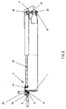
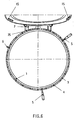
- die Draufsicht auf den Deckel für eine Mannlochöffnung bei einem nicht näher dargestellten Sudgefäß;
- Figur 2
- eine Schnittansicht entlang der Schnittlinie B-B der Figur 1, wobei der Verriegelungsbolzen 6 in die Schnittebene hineingedreht ist;
- Figur 3
- die Seitenansicht H in Figur 1;
- Figur 4
- die Seitenansicht C der Figur 5;
- Figur 5
- die Seitenansicht des geschlossenen Deckels in der linken Hälfte geschnitten;
- Figur 6
- eine Draufsicht auf das Mannloch bei geöffnetem Deckel.
Claims (10)
- Sudgefäß mit wenigstens einer von einer Zarge umgebenen Mannlochöffnung, die mit einem mittels einer Verriegelungseinrichtung verriegelbaren Deckel verschließbar ist, wobei die Vemegetungseinrichtung einen drehbaren Verriegelungsring aufweist,
dadurch gekennzeichnet, dass
der Verriegelungsring (3, 3a, 3b) an der Außenseite der Zarge (1) gelagert und wenigstens einen Verriegelungsbolzen (6) aufweist, der mit einer in einem Kragen (2a) des Deckels (2) ausgebildeten Ausnehmung (15) zusammenarbeitet. - Sudgefäß nach Anspruch 1,
dadurch gekennzeichnet, dass
der Verriegelungsring (3) aus zwei miteinander verbindbaren Ringen (3a, 3b) besteht, die eine U-förmige Aufnahme (10) für einen Lagerring (20) bilden, der seinerseits an der Außenwand der Zarge (1) in einer dort korrespondierend ausgebildeten Ringnut (9) liegt. - Sudgefäß nach Anspruch 1 oder 2,
dadurch gekennzeichnet, dass
die Ausnehmung (15) einen in Schließrichtung weisenden und unten offenen Einlaufbereich (15a) aufweist, an den sich ein geschlossener, in Umfangsrichtung weisender Verriegelungsabschnitt (15b) anschließt. - Sudgefäß nach Anspruch 3,
dadurch gekennzeichnet, dass
die mit dem Verriegelungsbolzen (6) zusammenwirkende Begrenzungsfläche (15c) der Ausnehmung (15) als zur Verriegelungsendposition leicht ansteigende Rampe ausgebildet ist, die in einer Verriegelungsvertiefung (15d) endet. - Sudgefäß nach wenigstens einem der vorangegangenen Ansprüche,
dadurch gekennzeichnet, dass
an der Außenseite der Zarge (1) ein Endschalter (21) angeordnet ist, der mit einem Schaltstift (22) mit dem Verriegelungsring zusammenwirkt. - Sudgefäß nach Anspruch 5,
dadurch gekennzeichnet, dass
der Verriegelungsring eine Schaltfläche (19) aufweist, die den Schaltstift (22) beim Verdrehen aus der Verschließposition in die Öffnungsposition vor Erreichen der Öffnungsposition betätigt. - Sudgefäß nach wenigstens einem der vorangegangenen Ansprüche,
dadurch gekennzeichnet, dass
im Bereich der Lager (18) für den Deckel (2) wenigstens eine Rastscheibe (7) mit dem Deckel beim Öffnen und Schließen drehend angeordnet ist, die eine Rastfläche (7a) aufweist, die in der Öffnungsposition des Verriegelungsrings (3) in eine dort ausgebildete Rille (25) beim Öffnen des Deckels einläuft und damit ein Rückdrehen des Verriegelungsrings blockiert. - Sudgefäß nach Anspruch 7,
dadurch gekennzeichnet, dass
die Rastscheibe (7) eine Anschlagnase (8) aufweist, die die maximale Öffnungsstellung durch Anlage an der Unterseite des Verriegelungsrings (3) bestimmt. - Sudgefäß nach wenigstens einem der vorangegangenen Ansprüche,
dadurch gekennzeichnet, dass
am deckelseitigen Rand (1a) der Zarge (1) eine umlaufende Dichtung (24) angeordnet ist, die so ausgebildet ist, dass bei Druckerhöhung im Innem des Sudgefäßes die Dichtkraft zwischen Deckel und Dichtung erhöht ist. - Sudgefäß nach wenigstens einem der vorangegangenen Ansprüche,
dadurch gekennzeichnet, dass
im Kragen des Deckels und im Verriegelungsring in Verriegelungsposition fluchtende Durchbrechungen ausgebildet sind, durch die ein Steckschloßschließzylinder (26) abschließbar eingesetzt werden kann.
Applications Claiming Priority (2)
| Application Number | Priority Date | Filing Date | Title |
|---|---|---|---|
| DE29700558U | 1997-01-14 | ||
| DE29700558U DE29700558U1 (de) | 1997-01-14 | 1997-01-14 | Sudgefäß mit Mannlochöffnung |
Publications (3)
| Publication Number | Publication Date |
|---|---|
| EP0853120A2 EP0853120A2 (de) | 1998-07-15 |
| EP0853120A3 EP0853120A3 (de) | 2002-10-16 |
| EP0853120B1 true EP0853120B1 (de) | 2005-04-27 |
Family
ID=8034545
Family Applications (1)
| Application Number | Title | Priority Date | Filing Date |
|---|---|---|---|
| EP19980100077 Expired - Lifetime EP0853120B1 (de) | 1997-01-14 | 1998-01-05 | Sudgefäss mit Mannlochöffnung |
Country Status (6)
| Country | Link |
|---|---|
| US (1) | US5957318A (de) |
| EP (1) | EP0853120B1 (de) |
| JP (1) | JP2942953B2 (de) |
| BR (1) | BR9800321A (de) |
| DE (2) | DE29700558U1 (de) |
| ES (1) | ES2241068T3 (de) |
Families Citing this family (3)
| Publication number | Priority date | Publication date | Assignee | Title |
|---|---|---|---|---|
| US20150272147A1 (en) * | 2014-03-26 | 2015-10-01 | Sharon Ericson | Uv light-blocking fermenting container system and related methods |
| EP3959151B1 (de) | 2019-04-23 | 2024-04-03 | Berry Global, Inc. | Selektiv zu öffnender verschluss für einen behälter |
| EP4403506B1 (de) * | 2023-01-17 | 2025-05-07 | Sacpro AB | Inversionseinheit mit fenster |
Family Cites Families (21)
| Publication number | Priority date | Publication date | Assignee | Title |
|---|---|---|---|---|
| US1848954A (en) * | 1932-03-08 | Cap fob eaiiiator hecks abtd the like | ||
| US2022868A (en) * | 1933-10-06 | 1935-12-03 | Nat Pressure Cooker Co | Pressure cooker |
| US2431905A (en) * | 1945-03-16 | 1947-12-02 | Robert J Anicetti | Quick locking furnace base plate |
| US2583073A (en) * | 1947-11-29 | 1952-01-22 | Jackson & Church Company | High-pressure steam kiln |
| US3076577A (en) * | 1962-01-02 | 1963-02-05 | Red Point Corp | Quick-release closure for pressure vessels |
| US3488883A (en) * | 1968-08-08 | 1970-01-13 | Welding & Steel Fabrication Co | Sealed door leveling system |
| JPS5421484B2 (de) * | 1974-01-26 | 1979-07-31 | ||
| US3951300A (en) * | 1974-07-01 | 1976-04-20 | Vereinigte Edelstahlwerke Aktiengesellschaft (Vew) | Pressure vessel |
| US4466551A (en) * | 1983-02-28 | 1984-08-21 | Leung Kam F | Closure device |
| JPS6259518A (ja) * | 1985-09-09 | 1987-03-16 | Mizusawa Ind Chem Ltd | 合成ヘクトライトの製法 |
| JP2630453B2 (ja) * | 1988-11-25 | 1997-07-16 | コニカ株式会社 | カラー画像形成装置 |
| US4944233A (en) * | 1989-06-12 | 1990-07-31 | Acf Industries, Incorporated | Hatch arrangement for covered hopper cars |
| DE9010033U1 (de) * | 1990-07-02 | 1990-10-04 | Umformtechnik Hausach GmbH, 7613 Hausach | Behälter mit Deckel |
| US5064082A (en) * | 1990-04-27 | 1991-11-12 | Elizabeth Arden Company, Division Of Conopco, Inc. | Compartmented container having a seal member and magnifying lid |
| WO1992019136A1 (en) * | 1991-04-24 | 1992-11-12 | Shamis Neal B | Closure system for covered receptacles and the like |
| US5072850A (en) * | 1991-04-25 | 1991-12-17 | Gagnon Robert M | Receptacle for foodstuffs and the like |
| DE9111870U1 (de) * | 1991-09-23 | 1991-11-14 | Anton Steinecker Entwicklungs-GmbH & Co., 8050 Freising | Sudgefäß mit einer durch einen Deckel verschließbaren Mannlochöffnung |
| JP2934811B2 (ja) * | 1994-09-05 | 1999-08-16 | 株式会社平山製作所 | 容器蓋ロック装置 |
| EP0769642B1 (de) * | 1995-10-11 | 2002-07-10 | Hirayama Manufacturing Corporation | Schlossvorrichtung für Behälter |
| KR0128775Y1 (ko) * | 1995-12-07 | 1998-10-15 | 문무영 | 전기압력솥의 압력뚜껑 자동 개폐로크장치 |
| US5727704A (en) * | 1996-07-23 | 1998-03-17 | Ideal Ideas, Inc. | Child resistant cap and safety collar ring having unique boss arrangements |
-
1997
- 1997-01-14 DE DE29700558U patent/DE29700558U1/de not_active Expired - Lifetime
-
1998
- 1998-01-05 EP EP19980100077 patent/EP0853120B1/de not_active Expired - Lifetime
- 1998-01-05 DE DE59812751T patent/DE59812751D1/de not_active Expired - Lifetime
- 1998-01-05 ES ES98100077T patent/ES2241068T3/es not_active Expired - Lifetime
- 1998-01-09 US US09/005,084 patent/US5957318A/en not_active Expired - Fee Related
- 1998-01-14 JP JP583698A patent/JP2942953B2/ja not_active Expired - Lifetime
- 1998-01-14 BR BR9800321A patent/BR9800321A/pt not_active IP Right Cessation
Also Published As
| Publication number | Publication date |
|---|---|
| EP0853120A3 (de) | 2002-10-16 |
| ES2241068T3 (es) | 2005-10-16 |
| BR9800321A (pt) | 1999-06-08 |
| DE29700558U1 (de) | 1997-03-06 |
| US5957318A (en) | 1999-09-28 |
| DE59812751D1 (de) | 2005-06-02 |
| JPH10273157A (ja) | 1998-10-13 |
| JP2942953B2 (ja) | 1999-08-30 |
| EP0853120A2 (de) | 1998-07-15 |
Similar Documents
| Publication | Publication Date | Title |
|---|---|---|
| DE69913483T2 (de) | Vorrichtung zum verriegeln/entriegeln eines dampfdruck-kochtopfs mit bajonettverschluss | |
| DE69916478T2 (de) | Sicherheitsvorrichtung zum öffnen von damfdruckkochtöpfen mit bajonettverschluss | |
| EP0139772B1 (de) | Dampfdruckkochtopf | |
| EP0499058B1 (de) | Deckel mit einem Ventilknopf für ein Kochgeschirr | |
| EP2000061B1 (de) | Überdruck-Kochtopf | |
| DE7012314U (de) | Sicherheitsvorrichtung fuer verriegelungen zwischen dichten kammern. | |
| EP3887017B1 (de) | Filtervorrichtung zur trinkwasserfilterung | |
| WO1990008729A1 (de) | Zapfkopf für keg-armaturen | |
| DE3640440C2 (de) | ||
| EP0853120A2 (de) | Sudgefäss mit Mannlochöffnung | |
| DE69103838T2 (de) | Auseinandernehmbarer Behälter, der für einen internen Druck ausgelegt ist. | |
| WO2003064897A2 (de) | Schliessvorrichtung für einen behälter | |
| EP0720829B1 (de) | Garvorrichtung sowie Deckel für Gargefäss | |
| DE2217344C2 (de) | Staubkappe und Einrichtung zum Arretieren der Sitzscheibe eines Ventils für flüssige Nahrungsmittel | |
| DE102016003038B3 (de) | Schnellverschlussdom | |
| CH619359A5 (en) | Closure safeguard on a pressure cooker | |
| DE19532707C2 (de) | Kochfeld für eine Haushaltsküche | |
| DE3731867C2 (de) | ||
| DE10315797B4 (de) | Verschlussmechanismus für ein Behältnis mit Deckel | |
| DE8815401U1 (de) | Verriegelungsvorrichtung, insbesondere für Türen von unter Druck stehenden Rotationsbehältern | |
| DE4105436C2 (de) | Sanitäre Wandarmatur | |
| DE3626746C2 (de) | ||
| CH596480A5 (en) | Rapid action closure for pressure or vacuum container | |
| CH673008A5 (de) | ||
| DE102007005037A1 (de) | Zapfvorrichtung für fassförmige Getränkebehälter |
Legal Events
| Date | Code | Title | Description |
|---|---|---|---|
| PUAI | Public reference made under article 153(3) epc to a published international application that has entered the european phase |
Free format text: ORIGINAL CODE: 0009012 |
|
| AK | Designated contracting states |
Kind code of ref document: A2 Designated state(s): AT BE CH DE DK ES FI FR GB GR IE IT LI LU MC NL PT SE |
|
| AX | Request for extension of the european patent |
Free format text: AL;LT;LV;MK;RO;SI |
|
| PUAL | Search report despatched |
Free format text: ORIGINAL CODE: 0009013 |
|
| AK | Designated contracting states |
Kind code of ref document: A3 Designated state(s): AT BE CH DE DK ES FI FR GB GR IE IT LI LU MC NL PT SE |
|
| AX | Request for extension of the european patent |
Free format text: AL;LT;LV;MK;RO;SI |
|
| RIC1 | Information provided on ipc code assigned before grant |
Free format text: 7C 12C 13/02 A, 7B 65D 90/10 B |
|
| 17P | Request for examination filed |
Effective date: 20030416 |
|
| AKX | Designation fees paid |
Designated state(s): BE DE ES GB |
|
| GRAP | Despatch of communication of intention to grant a patent |
Free format text: ORIGINAL CODE: EPIDOSNIGR1 |
|
| GRAS | Grant fee paid |
Free format text: ORIGINAL CODE: EPIDOSNIGR3 |
|
| GRAA | (expected) grant |
Free format text: ORIGINAL CODE: 0009210 |
|
| AK | Designated contracting states |
Kind code of ref document: B1 Designated state(s): BE DE ES GB |
|
| REG | Reference to a national code |
Ref country code: GB Ref legal event code: FG4D Free format text: NOT ENGLISH |
|
| GBT | Gb: translation of ep patent filed (gb section 77(6)(a)/1977) |
Effective date: 20050427 |
|
| REG | Reference to a national code |
Ref country code: IE Ref legal event code: FG4D Free format text: LANGUAGE OF EP DOCUMENT: GERMAN |
|
| REF | Corresponds to: |
Ref document number: 59812751 Country of ref document: DE Date of ref document: 20050602 Kind code of ref document: P |
|
| REG | Reference to a national code |
Ref country code: ES Ref legal event code: FG2A Ref document number: 2241068 Country of ref document: ES Kind code of ref document: T3 |
|
| PLBE | No opposition filed within time limit |
Free format text: ORIGINAL CODE: 0009261 |
|
| STAA | Information on the status of an ep patent application or granted ep patent |
Free format text: STATUS: NO OPPOSITION FILED WITHIN TIME LIMIT |
|
| 26N | No opposition filed |
Effective date: 20060130 |
|
| PGFP | Annual fee paid to national office [announced via postgrant information from national office to epo] |
Ref country code: ES Payment date: 20130207 Year of fee payment: 16 Ref country code: GB Payment date: 20130102 Year of fee payment: 16 |
|
| PGFP | Annual fee paid to national office [announced via postgrant information from national office to epo] |
Ref country code: BE Payment date: 20140114 Year of fee payment: 17 |
|
| GBPC | Gb: european patent ceased through non-payment of renewal fee |
Effective date: 20140105 |
|
| PG25 | Lapsed in a contracting state [announced via postgrant information from national office to epo] |
Ref country code: GB Free format text: LAPSE BECAUSE OF NON-PAYMENT OF DUE FEES Effective date: 20140105 |
|
| REG | Reference to a national code |
Ref country code: ES Ref legal event code: FD2A Effective date: 20150331 |
|
| PG25 | Lapsed in a contracting state [announced via postgrant information from national office to epo] |
Ref country code: ES Free format text: LAPSE BECAUSE OF NON-PAYMENT OF DUE FEES Effective date: 20140106 |
|
| PG25 | Lapsed in a contracting state [announced via postgrant information from national office to epo] |
Ref country code: BE Free format text: LAPSE BECAUSE OF NON-PAYMENT OF DUE FEES Effective date: 20150131 |
|
| PGFP | Annual fee paid to national office [announced via postgrant information from national office to epo] |
Ref country code: DE Payment date: 20151229 Year of fee payment: 19 |
|
| REG | Reference to a national code |
Ref country code: DE Ref legal event code: R119 Ref document number: 59812751 Country of ref document: DE |
|
| PG25 | Lapsed in a contracting state [announced via postgrant information from national office to epo] |
Ref country code: DE Free format text: LAPSE BECAUSE OF NON-PAYMENT OF DUE FEES Effective date: 20170801 |