EP0720829B1 - Garvorrichtung sowie Deckel für Gargefäss - Google Patents
Garvorrichtung sowie Deckel für Gargefäss Download PDFInfo
- Publication number
- EP0720829B1 EP0720829B1 EP95116953A EP95116953A EP0720829B1 EP 0720829 B1 EP0720829 B1 EP 0720829B1 EP 95116953 A EP95116953 A EP 95116953A EP 95116953 A EP95116953 A EP 95116953A EP 0720829 B1 EP0720829 B1 EP 0720829B1
- Authority
- EP
- European Patent Office
- Prior art keywords
- lid
- valve
- cooking
- holding
- closing
- Prior art date
- Legal status (The legal status is an assumption and is not a legal conclusion. Google has not performed a legal analysis and makes no representation as to the accuracy of the status listed.)
- Expired - Lifetime
Links
- 238000010411 cooking Methods 0.000 title claims abstract description 50
- 238000007789 sealing Methods 0.000 claims abstract description 5
- 238000007599 discharging Methods 0.000 claims 1
- 230000002093 peripheral effect Effects 0.000 claims 1
- 210000000078 claw Anatomy 0.000 description 4
- 239000007789 gas Substances 0.000 description 3
- 238000004140 cleaning Methods 0.000 description 1
- 238000010276 construction Methods 0.000 description 1
- 238000011109 contamination Methods 0.000 description 1
- 230000008878 coupling Effects 0.000 description 1
- 238000010168 coupling process Methods 0.000 description 1
- 238000005859 coupling reaction Methods 0.000 description 1
- 230000008034 disappearance Effects 0.000 description 1
- 230000000694 effects Effects 0.000 description 1
- 239000013013 elastic material Substances 0.000 description 1
- 230000005484 gravity Effects 0.000 description 1
- 238000010438 heat treatment Methods 0.000 description 1
- 230000003993 interaction Effects 0.000 description 1
- 238000004519 manufacturing process Methods 0.000 description 1
- 239000002184 metal Substances 0.000 description 1
- 230000002028 premature Effects 0.000 description 1
Images


Classifications
-
- A—HUMAN NECESSITIES
- A47—FURNITURE; DOMESTIC ARTICLES OR APPLIANCES; COFFEE MILLS; SPICE MILLS; SUCTION CLEANERS IN GENERAL
- A47J—KITCHEN EQUIPMENT; COFFEE MILLS; SPICE MILLS; APPARATUS FOR MAKING BEVERAGES
- A47J27/00—Cooking-vessels
- A47J27/08—Pressure-cookers; Lids or locking devices specially adapted therefor
- A47J27/0804—Locking devices
- A47J27/0813—Locking devices using a clamping ring or clamping segments
Definitions
- the invention relates to a lid for a cooking vessel according to the preamble of claim 1 and one Cooking device according to the preamble of claim 10.
- Cooking devices using increased internal pressure, steam pots in particular, is partly with Met reluctance.
- Met reluctance There is a prejudice, such Cooking vessels are complicated to use and that by Heating the food increases the pressure inside Endangerment with itself.
- the generally unfounded However, there is fear of incorrect operation and its consequences further spread the time and energy saving as well against nutritionally friendly cooking appliances.
- the steam pressure pot according to the DE 31 23 066 C2 can, however, due to the eccentric arrangement feel of the handle when handling it convey.
- the focus that is not under the handle of the cooking device causes a tilt when lifting and requires extra attention when parking.
- the cantilevered arrangement of the handles costs furthermore space for cooking and additional space.
- the lid disclosed in EP 0491 324 has similar disadvantages, which two clamping segments each articulated on a pivot axis includes the one with a pivotable about a vertical axis Locking lever are connected. The operation of this on the outer edge of the Lid arranged locking lever can only be carried out with two hands be otherwise there is a risk that the pot on the Stovetop moves or tilts. This also applies to that in DE 3327439 disclosed, at least two-part cover, in which flanged edge sections under counter edge sections of the Pot grip that they prevent the lid from lifting and the Operating handle extends radially from the center of the lid to one side extends.
- the invention is based, which alleviate the disadvantages described above and in particular through the safer and easier handling to create increased acceptance.
- the resulting compact structure without side protruding controls continue to allow easier and faster handling. It's through that two-sided attachment of the holding and operating handle One-handed operation when opening and closing the locking ring alone possible from above, and the closed cooking vessel can also be in the filled and heated condition much safer handle.
- the center of gravity directly below the breakpoint excludes unintentional tipping movements, and when it is switched off
- the lid can be easily removed by turning the Locking ring opened by means of the single handle element and then removed to the side.
- Across from Steam pressure pots with bayonet connection will increase security of the closed cooking vessel through the essentially full grip under 360 ° of the outside Edge increased by the locking ring.
- the plant of the Locking ring on a metallic surface of the cover reduces the frictional forces when turning the locking ring against a metal / rubber contact.
- the handle has two elongated, parallel, arcuate supports on the attached at both ends to the locking ring Holding sections are connected to each other, at least one of the holding sections is directed towards the center of the lid Projection and the lid associated with defined positions Symbols is already at a glance from above to recognize without a doubt whether the cooking vessel is correct is closed or still open.
- Symbols is already at a glance from above to recognize without a doubt whether the cooking vessel is correct is closed or still open.
- corresponding pictograms to the center of the lid directed projection opposite each other closed or an open cooking vessel.
- the simple and safe one-hand operability will supported by one in one of the holding sections longitudinally arranged actuator which by is accessible from above and when he clicks on an in Close position of the cover of the valve underneath acts. This allows one finger to hold the hand the cooking vessel is evaporated.
- valve connected to the sealing element elongated bodies in a cooking vessel under pressure Recess, which locks the lid against opening is also only under slight pressure Can no longer be opened.
- Accidents caused by premature Opening and escaping hot gases, which are about dirty, damp or oily lid seal possible were excluded. Only a properly ventilated one Cooking vessel can after the overpressure has been completely reduced be opened.
- valve has a spring-loaded slide, that with a control surface of at least one holding section can engage and only allows this in fully closed position of the lid closing of the valve, incorrect closing of the Cover no longer leads to a dangerous pressure build-up in the Guide inside the cooking device.
- the still open Valve leads overpressure audibly and warningly to the side.
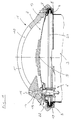
- the total designated 1 as a steam pressure pot, cooking device according to the invention a lid 2 and a Cooking vessel 3 on.
- the invention is without limitation of generality through the appropriately trained cover 2, however any cooking vessels 3 applicable, an upper, for Side, widened, annular edge 4.
- This cooking vessel 3 is better understood in FIG. 1 shown transparently.
- the cover 2 essentially comprises one circular, slightly arched base 5, in which is attached to a valve 6 with a fluid-tight seat.
- the outer circumference of the base body 5 is one Locking ring 7 with U-shaped profile rotatable on the base body 5 held.
- About a little less than half the outer circumference the base body 5 has a flange 8 which in the 2, open position of the lid 2 shown in about half the circumference of the laterally widened edge 4 can reach under.
- the cover 2 In the open position, the cover 2 is opened laterally the cooking vessel 4 pushed on and after rotation by means of handle attached to the locking ring on at least two sides 10 underneath the flange 9 of the locking ring 7 most of the remainder of the margin 4.
- the handle 10 comprises two in its central region elongated, parallel, arched supports 11, 12, which at both ends by the locking ring 7 attached holding sections 13, 14 connected to each other are.
- the holding section 14 has one towards the center of the lid directed projection 15, depending on the position assigned pictograms indicates which through the free space between the beams 11, 12 clearly visible from above are.
- An actuating member 14 is located in the holding section 14 longitudinally displaceable by its own weight in the lower one End position held.
- the actuator 16 In the closed position of the lid the actuator 16 is approximately above the Valve 6, of which it is in the interior of the pressure increase Cooking device 1 is lifted into its upper end position.
- the valve body 17 provided with the sealing element 18 is an essentially cylindrical, elongated body in the event of an increase in pressure due to initially escaping on this passing gases raised and immersed in the recess 19 released by actuating element 16.
- the actuator can be designed in a striking color, so that by its emergence a corresponding one Signal effect is achieved. His impression does that Stepping back of the valve body 17 thus opens the valve from the closed position shown enlarged in FIG. 4 and allowed by a side recess 20 and the remaining free space between valve body 17 and valve housing the side outlet of gases to the steam outlet openings 22 arranged in the holding section 14, as shown in Fig. 1.
- valve body 17 Inside the valve body 17 is preferably a Pressure relief valve 21 arranged in the known per se Way by a ball biased by a spring above a through hole through the valve body 17 is formed to the inside of the cooking device.
- valve 6 Slider 23 held laterally displaceable.
- the slide 23 has a nose-like projection 24 which is spring-loaded on control surfaces 25, 26 of the holding sections 13, 14 slides along.
- the control surfaces 25, 26 have, as in FIG. 5, the complete closing or the rest positions assigned to complete opening training depressions. Through the control surface 26 the slider 23 moved so that the otherwise the tab 27 overlapping the tab 27 upwards releases.
- the lid can have 2 more Fittings 29, such as pressure or temperature displays, include.
Landscapes
- Engineering & Computer Science (AREA)
- Food Science & Technology (AREA)
- Cookers (AREA)
- Commercial Cooking Devices (AREA)
Description
Es zeigen:
- Fig. 1
- einen Querschnitt entlang der Linie A-A aus Fig. 3 durch einen in geschlossener Stellung auf einem durchsichtigen Gargefäß angeordneten erfindungsgemäßen Deckel,
- Fig. 2
- einen Querschnitt entlang der Linie A-A aus Fig. 3 durch einen in geöffneter Stellung vom Gargefäß abgenommenen Deckel,
- Fig. 3
- eine teilweise aufgebrochene Darstellung eines Deckels in geschlossener Stellung von oben,
- Fig. 4
- einen Querschnitt in Längsrichtung durch das Ventil in seiner geschlossenen Stellung und
- Fig. 5
- eine Aufsicht von oben auf das Ventil mit einem Teil eines Halteabschnitt des Griffs.
Claims (10)
- Deckel (2) für ein Gargefäß (3), insbesondere für einen Dampfdrucktopf, mit einem umlaufenden, sich zur Seite hin erstreckenden oberen Rand (4), wobei der Deckel (2) in aufgesetzter, jedoch geöffneter Stellung zumindest einen Teil des Randes untergreift und beim Schließen mittels eines eine seitliche Umbördelung (9) aufweisenden drehbaren Schließrings (7) im wesentlichen den verbleibenden Teil des Randes untergreift, bei welchem vorzugsweise eine fluiddichte Ringdichtung (30) den Deckel (2) zum Gargefäß (3) abdichtet, gekennzeichnet durch einen Halte- und Bedienungsgriff (10), der sich in etwa über den gesamten Durchmesser des Deckels (2) erstreckt und an zwei gegenüberliegenden Seiten mit dem Schließring (7) verbunden ist.
- Deckel nach Anspruch 1, dadurch gekennzeichnet, daß der Halte- und Bedienungsgriff (10) in seinem Mittenbereich zwei längliche, sich parallel erstreckende bogenförmige Träger (11, 12) aufweist, die an ihren beiden Enden durch am Schließring (7) befestigte Halteabschnitte (13, 14) miteinander verbunden sind, wobei zumindest einer der Halteabschnitte (14) einen zur Deckelmitte gerichteten Vorsprung (15) und der Deckel (2) definierten Stellungen zugeordnete Symbole aufweist.
- Deckel nach Anspruch 1 oder 2, dadurch gekennzeichnet, daß in einem der Halteabschnitte (14) ein Betätigungsorgan (16) längsverschieblich und von oben her zugänglich angeordnet ist, das bei seinem Eindrücken auf ein in Schließstellung des Deckels darunterliegendes Ventil (6) einwirkt, um das Druckentlasten des Gargefäßes (3) zu bewirken.
- Deckel nach einem der Ansprüche 1 bis 3, dadurch gekennzeichnet, daß in dem auf der Seite des Betätigungsorgans (6) gelegenen Halteabschnitt (14) eine Dampfauslaßöffnung (22) zur Außenseite des Deckels (2) hin angeordnet ist.
- Deckel nach Anspruch 3 oder 4, dadurch gekennzeichnet, daß ein mit einem Dichtelement (18) des Ventils (6) verbundener länglicher Körper (17) bei unter Druck stehendem Gargefäß (3) das Betägigungsorgan (16) hebt.
- Deckel nach Anspruch 5, dadurch gekennzeichnet, daß der längliche Körper (17) bei unter Druck stehendem Gargefäß (3) in eine Ausnehmung (19) taucht, wodurch der Deckel (2) gegen Öffnen verriegelt ist.
- Deckel nach einem der Ansprüche 1 bis 6, dadurch gekennzeichnet, daß das Ventil (6) einen federbelasteten Schieber (23) aufweist, der mit einer Steuerfläche (25, 26) zumindest eines Halteabschnittes (13, 14) in Eingriff geraten kann und nur in vollständig geschlossener Stellung des Deckels (2) das Schließen des Ventils (6) gestattet.
- Deckel nach Anspruch 7, dadurch gekennzeichnet, daß der Schieber (23) einen nasenartigen Vorsprung aufweist und die Steuerflächen (25, 26) beider Halteabschnitte (13, 14) Raststellungen ausbilden, die jeweils einer vollständigen Öffnung und einem vollständigen Schließen des Deckels (2) zugeordnet sind.
- Deckel nach Anspruch 8, dadurch gekennzeichnet, daß in vollständig geöffneter Stellung des Schließrings (7) ein Vorsprung (28) am Halteabschnitt (13) das Schließen des Ventils (6) verhindert.
- Garvorrichtung, insbesondere Dampfdrucktopf, mit einem Gargefäß, gekennzeichnet durch einen Deckel (2) nach einem der Ansprüche von 1 bis 9.
Applications Claiming Priority (2)
| Application Number | Priority Date | Filing Date | Title |
|---|---|---|---|
| DE29500125U | 1995-01-05 | ||
| DE29500125U DE29500125U1 (de) | 1995-01-05 | 1995-01-05 | Garvorrichtung sowie Deckel für Gargefäß |
Publications (2)
| Publication Number | Publication Date |
|---|---|
| EP0720829A1 EP0720829A1 (de) | 1996-07-10 |
| EP0720829B1 true EP0720829B1 (de) | 1998-03-25 |
Family
ID=8002199
Family Applications (1)
| Application Number | Title | Priority Date | Filing Date |
|---|---|---|---|
| EP95116953A Expired - Lifetime EP0720829B1 (de) | 1995-01-05 | 1995-10-27 | Garvorrichtung sowie Deckel für Gargefäss |
Country Status (7)
| Country | Link |
|---|---|
| EP (1) | EP0720829B1 (de) |
| AT (1) | ATE164297T1 (de) |
| DE (2) | DE29500125U1 (de) |
| DK (1) | DK0720829T3 (de) |
| ES (1) | ES2116028T3 (de) |
| GR (1) | GR3026587T3 (de) |
| TR (1) | TR199501704A2 (de) |
Families Citing this family (5)
| Publication number | Priority date | Publication date | Assignee | Title |
|---|---|---|---|---|
| DE29719066U1 (de) | 1997-10-27 | 1999-03-04 | Synkrona Ag, Stans | Fernbedienbare Einrichtung für das Abdampfen von mit Überdruck betriebenen Gargefäßen |
| DE102009053352A1 (de) | 2009-11-17 | 2011-05-19 | Axel R. Dr. Hidde | Gargefäß mit Deckelmodul und Topfmodul |
| CN102697385B (zh) * | 2012-05-14 | 2016-12-14 | 谢勇 | 限压值可自动切换的电压力锅 |
| CN209346659U (zh) * | 2018-10-08 | 2019-09-06 | 佛山市顺德区美的电热电器制造有限公司 | 压力烹饪设备 |
| WO2021173730A1 (en) * | 2020-02-25 | 2021-09-02 | Rj Brands, Llc | Cooking device and system |
Family Cites Families (7)
| Publication number | Priority date | Publication date | Assignee | Title |
|---|---|---|---|---|
| AT312840B (de) * | 1970-12-02 | 1974-01-25 | Exp Metall Ind G M B H | Druckausgleichsventil an Druckkochtöpfen |
| DE2534709C3 (de) | 1975-08-04 | 1981-02-19 | Amc International Alfa Metalcraft Corporation Ag, Rotkreuz (Schweiz) | Dampfdruckkochtopf |
| DE3123066C2 (de) * | 1981-06-11 | 1983-05-19 | Alfa Institut für hauswirtschaftliche Produkt- und Verfahrens-Entwicklung GmbH, 6228 Eltville | Deckel für Dampfdruckkochtöpfe |
| DE3232907A1 (de) * | 1982-09-04 | 1984-03-08 | Boehm, Hans-Georg, Dipl.-Phys. Dr.rer.nat, 6242 Kronberg | Dampfdruckkochtopf |
| DE3327439A1 (de) * | 1983-07-29 | 1985-02-07 | Württembergische Metallwarenfabrik AG, 7340 Geislingen | Deckel fuer einen dampfdruckkochtopf |
| KR0181712B1 (ko) | 1990-05-26 | 1999-03-20 | 호르스트 슐츠 | 조리용기 |
| DE4040489A1 (de) * | 1990-12-18 | 1992-07-16 | Silit Werke | Deckel fuer kochtoepfe mit umgelegtem rand |
-
1995
- 1995-01-05 DE DE29500125U patent/DE29500125U1/de not_active Expired - Lifetime
- 1995-10-27 AT AT95116953T patent/ATE164297T1/de not_active IP Right Cessation
- 1995-10-27 DE DE59501703T patent/DE59501703D1/de not_active Expired - Fee Related
- 1995-10-27 DK DK95116953T patent/DK0720829T3/da active
- 1995-10-27 ES ES95116953T patent/ES2116028T3/es not_active Expired - Lifetime
- 1995-10-27 EP EP95116953A patent/EP0720829B1/de not_active Expired - Lifetime
- 1995-12-27 TR TR95/01704A patent/TR199501704A2/xx unknown
-
1998
- 1998-04-10 GR GR980400776T patent/GR3026587T3/el unknown
Also Published As
| Publication number | Publication date |
|---|---|
| ATE164297T1 (de) | 1998-04-15 |
| DE29500125U1 (de) | 1995-02-16 |
| GR3026587T3 (en) | 1998-07-31 |
| DE59501703D1 (de) | 1998-04-30 |
| DK0720829T3 (da) | 1998-12-07 |
| TR199501704A2 (tr) | 1996-07-21 |
| ES2116028T3 (es) | 1998-07-01 |
| EP0720829A1 (de) | 1996-07-10 |
Similar Documents
| Publication | Publication Date | Title |
|---|---|---|
| EP0499058B1 (de) | Deckel mit einem Ventilknopf für ein Kochgeschirr | |
| EP0568531B1 (de) | Kochgefäss | |
| DE69916478T2 (de) | Sicherheitsvorrichtung zum öffnen von damfdruckkochtöpfen mit bajonettverschluss | |
| DE2534709C3 (de) | Dampfdruckkochtopf | |
| DE102004056463B3 (de) | Kochgefäß | |
| EP1779753B1 (de) | Schnellkochtopf | |
| DE3400356C2 (de) | ||
| EP0032406A1 (de) | Dampfdruckkochtopf | |
| DE10014766C2 (de) | Dampfdruck-Kochtopf | |
| EP0720829B1 (de) | Garvorrichtung sowie Deckel für Gargefäss | |
| DE2705712C3 (de) | Deckelverriegelungs- und Druckentlastungseinrichtung an einem Dampfdruckkochtopf | |
| DE3010205C2 (de) | Dampfdruckkochtopf mit einem deckel, der den topf von innen her verschliesst | |
| DE8012674U1 (de) | Vorrichtung zur sicherung des deckels eines unter druck stehenden behaelters gegen die entriegelung | |
| EP0824467B1 (de) | Deckel für einen behälter | |
| DE4017067A1 (de) | Kochgefaess | |
| DE19907195C2 (de) | Isolierkanne | |
| DE4307960C2 (de) | Dampfdruckkochtopf mit Bajonettverschluß | |
| DE3123066C2 (de) | Deckel für Dampfdruckkochtöpfe | |
| EP0853120B1 (de) | Sudgefäss mit Mannlochöffnung | |
| DE2712636A1 (de) | Dampfdruckkochtopf | |
| DE2915919C3 (de) | Schnellkochtopf | |
| AT391412B (de) | Deckel fuer dampfdruckkochtoepfe | |
| AT405601B (de) | Zusatzdeckel für kochgefäss | |
| DE3011286C2 (de) | Druckkochkessel für Großküchen | |
| DE3027064A1 (de) | Dampfdruckkochtopf |
Legal Events
| Date | Code | Title | Description |
|---|---|---|---|
| PUAI | Public reference made under article 153(3) epc to a published international application that has entered the european phase |
Free format text: ORIGINAL CODE: 0009012 |
|
| AK | Designated contracting states |
Kind code of ref document: A1 Designated state(s): AT BE CH DE DK ES FR GB GR IE IT LI LU MC NL PT SE |
|
| 17P | Request for examination filed |
Effective date: 19961218 |
|
| 17Q | First examination report despatched |
Effective date: 19970128 |
|
| GRAG | Despatch of communication of intention to grant |
Free format text: ORIGINAL CODE: EPIDOS AGRA |
|
| GRAG | Despatch of communication of intention to grant |
Free format text: ORIGINAL CODE: EPIDOS AGRA |
|
| GRAH | Despatch of communication of intention to grant a patent |
Free format text: ORIGINAL CODE: EPIDOS IGRA |
|
| GRAH | Despatch of communication of intention to grant a patent |
Free format text: ORIGINAL CODE: EPIDOS IGRA |
|
| ITF | It: translation for a ep patent filed | ||
| GRAA | (expected) grant |
Free format text: ORIGINAL CODE: 0009210 |
|
| AK | Designated contracting states |
Kind code of ref document: B1 Designated state(s): AT BE CH DE DK ES FR GB GR IE IT LI LU MC NL PT SE |
|
| REF | Corresponds to: |
Ref document number: 164297 Country of ref document: AT Date of ref document: 19980415 Kind code of ref document: T |
|
| REG | Reference to a national code |
Ref country code: CH Ref legal event code: NV Representative=s name: BOVARD AG PATENTANWAELTE Ref country code: CH Ref legal event code: EP |
|
| GBT | Gb: translation of ep patent filed (gb section 77(6)(a)/1977) |
Effective date: 19980326 |
|
| ET | Fr: translation filed | ||
| REF | Corresponds to: |
Ref document number: 59501703 Country of ref document: DE Date of ref document: 19980430 |
|
| REG | Reference to a national code |
Ref country code: ES Ref legal event code: FG2A Ref document number: 2116028 Country of ref document: ES Kind code of ref document: T3 |
|
| REG | Reference to a national code |
Ref country code: IE Ref legal event code: FG4D Free format text: 79527 |
|
| REG | Reference to a national code |
Ref country code: PT Ref legal event code: SC4A Free format text: AVAILABILITY OF NATIONAL TRANSLATION Effective date: 19980325 |
|
| PG25 | Lapsed in a contracting state [announced via postgrant information from national office to epo] |
Ref country code: LU Free format text: LAPSE BECAUSE OF NON-PAYMENT OF DUE FEES Effective date: 19981027 |
|
| REG | Reference to a national code |
Ref country code: DK Ref legal event code: T3 |
|
| PLBE | No opposition filed within time limit |
Free format text: ORIGINAL CODE: 0009261 |
|
| STAA | Information on the status of an ep patent application or granted ep patent |
Free format text: STATUS: NO OPPOSITION FILED WITHIN TIME LIMIT |
|
| 26N | No opposition filed | ||
| PG25 | Lapsed in a contracting state [announced via postgrant information from national office to epo] |
Ref country code: MC Free format text: LAPSE BECAUSE OF NON-PAYMENT OF DUE FEES Effective date: 19990430 |
|
| REG | Reference to a national code |
Ref country code: GB Ref legal event code: IF02 |
|
| PGFP | Annual fee paid to national office [announced via postgrant information from national office to epo] |
Ref country code: GB Payment date: 20020924 Year of fee payment: 8 |
|
| PGFP | Annual fee paid to national office [announced via postgrant information from national office to epo] |
Ref country code: GR Payment date: 20020925 Year of fee payment: 8 |
|
| PGFP | Annual fee paid to national office [announced via postgrant information from national office to epo] |
Ref country code: PT Payment date: 20021003 Year of fee payment: 8 |
|
| PGFP | Annual fee paid to national office [announced via postgrant information from national office to epo] |
Ref country code: ES Payment date: 20021010 Year of fee payment: 8 |
|
| PGFP | Annual fee paid to national office [announced via postgrant information from national office to epo] |
Ref country code: FR Payment date: 20021017 Year of fee payment: 8 |
|
| PGFP | Annual fee paid to national office [announced via postgrant information from national office to epo] |
Ref country code: AT Payment date: 20021018 Year of fee payment: 8 |
|
| PGFP | Annual fee paid to national office [announced via postgrant information from national office to epo] |
Ref country code: SE Payment date: 20021021 Year of fee payment: 8 Ref country code: NL Payment date: 20021021 Year of fee payment: 8 Ref country code: DK Payment date: 20021021 Year of fee payment: 8 Ref country code: BE Payment date: 20021021 Year of fee payment: 8 |
|
| PGFP | Annual fee paid to national office [announced via postgrant information from national office to epo] |
Ref country code: IE Payment date: 20021024 Year of fee payment: 8 |
|
| PGFP | Annual fee paid to national office [announced via postgrant information from national office to epo] |
Ref country code: DE Payment date: 20021029 Year of fee payment: 8 Ref country code: CH Payment date: 20021029 Year of fee payment: 8 |
|
| PG25 | Lapsed in a contracting state [announced via postgrant information from national office to epo] |
Ref country code: IE Free format text: LAPSE BECAUSE OF NON-PAYMENT OF DUE FEES Effective date: 20031027 Ref country code: GB Free format text: LAPSE BECAUSE OF NON-PAYMENT OF DUE FEES Effective date: 20031027 Ref country code: AT Free format text: LAPSE BECAUSE OF NON-PAYMENT OF DUE FEES Effective date: 20031027 |
|
| PG25 | Lapsed in a contracting state [announced via postgrant information from national office to epo] |
Ref country code: SE Free format text: LAPSE BECAUSE OF NON-PAYMENT OF DUE FEES Effective date: 20031028 Ref country code: ES Free format text: LAPSE BECAUSE OF NON-PAYMENT OF DUE FEES Effective date: 20031028 |
|
| PG25 | Lapsed in a contracting state [announced via postgrant information from national office to epo] |
Ref country code: LI Free format text: LAPSE BECAUSE OF NON-PAYMENT OF DUE FEES Effective date: 20031031 Ref country code: CH Free format text: LAPSE BECAUSE OF NON-PAYMENT OF DUE FEES Effective date: 20031031 Ref country code: BE Free format text: LAPSE BECAUSE OF NON-PAYMENT OF DUE FEES Effective date: 20031031 |
|
| BERE | Be: lapsed |
Owner name: *SYNKRONA A.G. Effective date: 20031031 |
|
| PG25 | Lapsed in a contracting state [announced via postgrant information from national office to epo] |
Ref country code: PT Free format text: LAPSE BECAUSE OF NON-PAYMENT OF DUE FEES Effective date: 20040430 Ref country code: DK Free format text: LAPSE BECAUSE OF NON-PAYMENT OF DUE FEES Effective date: 20040430 |
|
| PG25 | Lapsed in a contracting state [announced via postgrant information from national office to epo] |
Ref country code: NL Free format text: LAPSE BECAUSE OF NON-PAYMENT OF DUE FEES Effective date: 20040501 Ref country code: DE Free format text: LAPSE BECAUSE OF NON-PAYMENT OF DUE FEES Effective date: 20040501 |
|
| PG25 | Lapsed in a contracting state [announced via postgrant information from national office to epo] |
Ref country code: GR Free format text: LAPSE BECAUSE OF NON-PAYMENT OF DUE FEES Effective date: 20040504 |
|
| EUG | Se: european patent has lapsed | ||
| REG | Reference to a national code |
Ref country code: DK Ref legal event code: EBP |
|
| REG | Reference to a national code |
Ref country code: CH Ref legal event code: PL |
|
| GBPC | Gb: european patent ceased through non-payment of renewal fee |
Effective date: 20031027 |
|
| PG25 | Lapsed in a contracting state [announced via postgrant information from national office to epo] |
Ref country code: FR Free format text: LAPSE BECAUSE OF NON-PAYMENT OF DUE FEES Effective date: 20040630 |
|
| NLV4 | Nl: lapsed or anulled due to non-payment of the annual fee |
Effective date: 20040501 |
|
| REG | Reference to a national code |
Ref country code: IE Ref legal event code: MM4A |
|
| REG | Reference to a national code |
Ref country code: FR Ref legal event code: ST Ref country code: PT Ref legal event code: MM4A Free format text: LAPSE DUE TO NON-PAYMENT OF FEES Effective date: 20040430 |
|
| REG | Reference to a national code |
Ref country code: ES Ref legal event code: FD2A Effective date: 20031028 |
|
| PG25 | Lapsed in a contracting state [announced via postgrant information from national office to epo] |
Ref country code: IT Free format text: LAPSE BECAUSE OF NON-PAYMENT OF DUE FEES;WARNING: LAPSES OF ITALIAN PATENTS WITH EFFECTIVE DATE BEFORE 2007 MAY HAVE OCCURRED AT ANY TIME BEFORE 2007. THE CORRECT EFFECTIVE DATE MAY BE DIFFERENT FROM THE ONE RECORDED. Effective date: 20051027 |