EP4403506B1 - Inversionseinheit mit fenster - Google Patents
Inversionseinheit mit fenster Download PDFInfo
- Publication number
- EP4403506B1 EP4403506B1 EP23151944.8A EP23151944A EP4403506B1 EP 4403506 B1 EP4403506 B1 EP 4403506B1 EP 23151944 A EP23151944 A EP 23151944A EP 4403506 B1 EP4403506 B1 EP 4403506B1
- Authority
- EP
- European Patent Office
- Prior art keywords
- window
- housing
- inversion unit
- locking mechanism
- assembly
- Prior art date
- Legal status (The legal status is an assumption and is not a legal conclusion. Google has not performed a legal analysis and makes no representation as to the accuracy of the status listed.)
- Active
Links
Images

Classifications
-
- B—PERFORMING OPERATIONS; TRANSPORTING
- B29—WORKING OF PLASTICS; WORKING OF SUBSTANCES IN A PLASTIC STATE IN GENERAL
- B29C—SHAPING OR JOINING OF PLASTICS; SHAPING OF MATERIAL IN A PLASTIC STATE, NOT OTHERWISE PROVIDED FOR; AFTER-TREATMENT OF THE SHAPED PRODUCTS, e.g. REPAIRING
- B29C63/00—Lining or sheathing, i.e. applying preformed layers or sheathings of plastics; Apparatus therefor
- B29C63/26—Lining or sheathing of internal surfaces
- B29C63/34—Lining or sheathing of internal surfaces using tubular layers or sheathings
- B29C63/36—Lining or sheathing of internal surfaces using tubular layers or sheathings being turned inside out
-
- B—PERFORMING OPERATIONS; TRANSPORTING
- B29—WORKING OF PLASTICS; WORKING OF SUBSTANCES IN A PLASTIC STATE IN GENERAL
- B29C—SHAPING OR JOINING OF PLASTICS; SHAPING OF MATERIAL IN A PLASTIC STATE, NOT OTHERWISE PROVIDED FOR; AFTER-TREATMENT OF THE SHAPED PRODUCTS, e.g. REPAIRING
- B29C67/00—Shaping techniques not covered by groups B29C39/00 - B29C65/00, B29C70/00 or B29C73/00
- B29C67/0014—Shaping techniques not covered by groups B29C39/00 - B29C65/00, B29C70/00 or B29C73/00 for shaping tubes or blown tubular films
- B29C67/0018—Turning tubes inside out
-
- B—PERFORMING OPERATIONS; TRANSPORTING
- B65—CONVEYING; PACKING; STORING; HANDLING THIN OR FILAMENTARY MATERIAL
- B65H—HANDLING THIN OR FILAMENTARY MATERIAL, e.g. SHEETS, WEBS, CABLES
- B65H75/00—Storing webs, tapes, or filamentary material, e.g. on reels
- B65H75/02—Cores, formers, supports, or holders for coiled, wound, or folded material, e.g. reels, spindles, bobbins, cop tubes, cans, mandrels or chucks
- B65H75/34—Cores, formers, supports, or holders for coiled, wound, or folded material, e.g. reels, spindles, bobbins, cop tubes, cans, mandrels or chucks specially adapted or mounted for storing and repeatedly paying-out and re-storing lengths of material provided for particular purposes, e.g. anchored hoses, power cables
- B65H75/38—Cores, formers, supports, or holders for coiled, wound, or folded material, e.g. reels, spindles, bobbins, cop tubes, cans, mandrels or chucks specially adapted or mounted for storing and repeatedly paying-out and re-storing lengths of material provided for particular purposes, e.g. anchored hoses, power cables involving the use of a core or former internal to, and supporting, a stored package of material
- B65H75/40—Cores, formers, supports, or holders for coiled, wound, or folded material, e.g. reels, spindles, bobbins, cop tubes, cans, mandrels or chucks specially adapted or mounted for storing and repeatedly paying-out and re-storing lengths of material provided for particular purposes, e.g. anchored hoses, power cables involving the use of a core or former internal to, and supporting, a stored package of material mobile or transportable
- B65H75/403—Carriage with wheels
-
- B—PERFORMING OPERATIONS; TRANSPORTING
- B65—CONVEYING; PACKING; STORING; HANDLING THIN OR FILAMENTARY MATERIAL
- B65H—HANDLING THIN OR FILAMENTARY MATERIAL, e.g. SHEETS, WEBS, CABLES
- B65H75/00—Storing webs, tapes, or filamentary material, e.g. on reels
- B65H75/02—Cores, formers, supports, or holders for coiled, wound, or folded material, e.g. reels, spindles, bobbins, cop tubes, cans, mandrels or chucks
- B65H75/34—Cores, formers, supports, or holders for coiled, wound, or folded material, e.g. reels, spindles, bobbins, cop tubes, cans, mandrels or chucks specially adapted or mounted for storing and repeatedly paying-out and re-storing lengths of material provided for particular purposes, e.g. anchored hoses, power cables
- B65H75/38—Cores, formers, supports, or holders for coiled, wound, or folded material, e.g. reels, spindles, bobbins, cop tubes, cans, mandrels or chucks specially adapted or mounted for storing and repeatedly paying-out and re-storing lengths of material provided for particular purposes, e.g. anchored hoses, power cables involving the use of a core or former internal to, and supporting, a stored package of material
- B65H75/44—Constructional details
- B65H75/4457—Arrangements of the frame or housing
- B65H75/4471—Housing enclosing the reel
-
- F—MECHANICAL ENGINEERING; LIGHTING; HEATING; WEAPONS; BLASTING
- F16—ENGINEERING ELEMENTS AND UNITS; GENERAL MEASURES FOR PRODUCING AND MAINTAINING EFFECTIVE FUNCTIONING OF MACHINES OR INSTALLATIONS; THERMAL INSULATION IN GENERAL
- F16J—PISTONS; CYLINDERS; SEALINGS
- F16J13/00—Covers or similar closure members for pressure vessels in general
- F16J13/16—Pivoted closures
- F16J13/18—Pivoted closures pivoted directly on the frame
-
- F—MECHANICAL ENGINEERING; LIGHTING; HEATING; WEAPONS; BLASTING
- F16—ENGINEERING ELEMENTS AND UNITS; GENERAL MEASURES FOR PRODUCING AND MAINTAINING EFFECTIVE FUNCTIONING OF MACHINES OR INSTALLATIONS; THERMAL INSULATION IN GENERAL
- F16L—PIPES; JOINTS OR FITTINGS FOR PIPES; SUPPORTS FOR PIPES, CABLES OR PROTECTIVE TUBING; MEANS FOR THERMAL INSULATION IN GENERAL
- F16L55/00—Devices or appurtenances for use in, or in connection with, pipes or pipe systems
- F16L55/18—Appliances for use in repairing pipes
-
- B—PERFORMING OPERATIONS; TRANSPORTING
- B65—CONVEYING; PACKING; STORING; HANDLING THIN OR FILAMENTARY MATERIAL
- B65H—HANDLING THIN OR FILAMENTARY MATERIAL, e.g. SHEETS, WEBS, CABLES
- B65H2701/00—Handled material; Storage means
- B65H2701/30—Handled filamentary material
- B65H2701/33—Hollow or hose-like material
-
- F—MECHANICAL ENGINEERING; LIGHTING; HEATING; WEAPONS; BLASTING
- F16—ENGINEERING ELEMENTS AND UNITS; GENERAL MEASURES FOR PRODUCING AND MAINTAINING EFFECTIVE FUNCTIONING OF MACHINES OR INSTALLATIONS; THERMAL INSULATION IN GENERAL
- F16L—PIPES; JOINTS OR FITTINGS FOR PIPES; SUPPORTS FOR PIPES, CABLES OR PROTECTIVE TUBING; MEANS FOR THERMAL INSULATION IN GENERAL
- F16L55/00—Devices or appurtenances for use in, or in connection with, pipes or pipe systems
- F16L55/16—Devices for covering leaks in pipes or hoses, e.g. hose-menders
- F16L55/162—Devices for covering leaks in pipes or hoses, e.g. hose-menders from inside the pipe
- F16L55/165—Devices for covering leaks in pipes or hoses, e.g. hose-menders from inside the pipe a pipe or flexible liner being inserted in the damaged section
- F16L55/1651—Devices for covering leaks in pipes or hoses, e.g. hose-menders from inside the pipe a pipe or flexible liner being inserted in the damaged section the flexible liner being everted
-
- F—MECHANICAL ENGINEERING; LIGHTING; HEATING; WEAPONS; BLASTING
- F16—ENGINEERING ELEMENTS AND UNITS; GENERAL MEASURES FOR PRODUCING AND MAINTAINING EFFECTIVE FUNCTIONING OF MACHINES OR INSTALLATIONS; THERMAL INSULATION IN GENERAL
- F16L—PIPES; JOINTS OR FITTINGS FOR PIPES; SUPPORTS FOR PIPES, CABLES OR PROTECTIVE TUBING; MEANS FOR THERMAL INSULATION IN GENERAL
- F16L55/00—Devices or appurtenances for use in, or in connection with, pipes or pipe systems
- F16L55/16—Devices for covering leaks in pipes or hoses, e.g. hose-menders
- F16L55/162—Devices for covering leaks in pipes or hoses, e.g. hose-menders from inside the pipe
- F16L55/165—Devices for covering leaks in pipes or hoses, e.g. hose-menders from inside the pipe a pipe or flexible liner being inserted in the damaged section
- F16L55/1652—Devices for covering leaks in pipes or hoses, e.g. hose-menders from inside the pipe a pipe or flexible liner being inserted in the damaged section the flexible liner being pulled into the damaged section
- F16L55/1654—Devices for covering leaks in pipes or hoses, e.g. hose-menders from inside the pipe a pipe or flexible liner being inserted in the damaged section the flexible liner being pulled into the damaged section and being inflated
Definitions
- the invention relates to the field of inversion units for pipe-relining and in particular to an inversion unit having a window that is easy to handle, in particular open and close.
- Inversion units are used to refurbish piping and plumbing systems in buildings and structures.
- the inversion units allow to reline pipes instead of removing old pipes and installing new pipes and therewith allow to provide for a smoother and quicker process of refurbishing piping and plumbing system.
- the reel is typically enclosed by a drum that is designed to be airtight when the sleeve is connected to an adapter for entering the piping system.
- the drum is pressurized with a gas, typically air, via a gas inlet. Due to the pressure in the drum and the connection to the adapter, the impregnated fabric is entering the pipe in an inverted manner.
- the inverted and impregnated fabric will therewith seal the piping once it is installed and cured.
- a window is typically provided on the drum as shown for instance in the US 2020/0263821 A1 .
- An opening formed in the drum, which opening is covered by the window is used so that the workers can reach into the drum to perform manual work in case of issues in the drum during operation or during reeling up of the impregnated fabric.
- the window in the US 2020/0263821 A1 is a lock that is screwed onto a thread of the opening of the drum.
- the size of the window in the US 2020/0263821 A1 is limited and the opening and the closing of the window takes time due to the screwing movement that is required.
- the present invention seeks to provide a larger window having a smooth and reliable locking mechanism.
- An object of the present invention is to provide an inversion unit that is easy to handle and provides for an efficient work process.
- the inventor of the present invention has discovered that it is possible to change the design of the window on the housing or drum of the inversion unit for better and smoother access to the window by using a bayonet mechanism in combination with a handle.
- a inversion unit comprising a housing, a reel for a liner partially arranged in the housing, and a base assembly.
- the housing is arranged on the base assembly, said housing comprising a gas inlet, an outlet for the liner, an opening comprising a window and a window locking mechanism being designed to be manoeuvred into an open position in which the window is open and/or unlocked and a closed position in which the window is closed and/or locked,
- the window locking mechanism is designed as a bayonet catch and comprises a motion link assembly and a matching projection assembly.
- the window locking mechanism further comprises a handle and a hinge, the handle being pivotably connected to the hinge wherein one of the motion link assembly or the matching projection assembly is arranged on the window and the other of the matching projection assembly or the motion link assembly is arranged on an edge of the opening.
- the hinge is arranged on the housing and the handle is pivotably connected to the window so that the window can be easily opened and closed in a bayonet catch manner using the handle.
- the above-described inversion unit improves the handling of the window using an efficient opening and closing mechanism embodied as the window locking mechanism.
- the above-described embodiment of the inversion unit further also covers the kinematic reversed arrangement of the motion link assembly and the matching projection assembly.
- the motion link assembly may either be arranged on an edge of the opening and the matching projection assembly on the window or the other way around.
- the window comprises a seal that is designed to seal the opening when the window locking mechanism is in the closed position.
- the seal allows to build up the gas pressure in the housing via the gas inlet in a controlled manner by sealing the inside of the housing.
- the opening may be larger than the outlet for the liner.
- the handle is designed as a lever that can be moved towards the housing for manoeuvring the window locking mechanism into the closed position and that can be moved away from the housing for manoeuvring the window locking mechanism into the open position.
- the handle in the form of a lever makes it very easy for an operator or worker to open and close the window using the window locking mechanism.
- the window can be rotated or pivotated away from the opening when the window locking mechanism is in its open position.
- the window can be moved out of the way when the window locking mechanism is in its open position.
- the opening may be substantially rectangular. This may allow to use standard components for the window and frame.
- the housing may comprise a gas outlet for better controlling the gas pressure in the housing.
- the base assembly can be disconnected from the housing and wherein the base assembly comprises a base and wheels.
- the disconnection of the inversion unit from the base assembly may improve the handling of the inversion unit in tight space(s).
- Using wheels connected to the base may improve mobility of the inversion unit and base assembly, respectively.
- the base assembly may further be provided with at least one swivelling wheel, which further improves the handling of the inversion unit and base assembly, respectively.
- the window further comprises a glass and a frame embedding the glass of the window, said frame being pivotably connected to the handle and said frame comprising the motion link assembly or matching projection assembly.
- the above may further improve the robustness of the window and the window locking mechanism.
- the frame may for example be clamped to the glass and the frame may be made of metal or the like whereby the motion link assembly and the matching projection assembly, respectively, may be integrally formed with the frame.
- the motion link assembly may be arranged in a first plane that is oriented perpendicular to a second plane defined by the window and wherein the matching projection assembly is projecting in a direction perpendicular to the first plane.
- the direction of the motion link of the motion link assembly is further oriented so that the window can slide in a linear motion once the handle is operated.
- the motion link assembly may comprise two to eight motion link elements, preferably four motion link elements.
- the motion link elements may be distributed equally on either side of the opening or window while the matching projecting assembly may comprise an equal amount of projections, which are equally distributed so that they match the motion link elements when the window is connected to the opening and when the window locking mechanism is moved into the closed position.
- Figure 1 illustrates an inversion unit 1 comprising a housing 2, a reel 4 for a liner arranged partially within the housing 2 and a base assembly 6.
- the housing 2 is formed as a drum but it may be formed as a hexagon, octagon, or any other suitable shape.
- the reel 4 comprises a manual wheel 44 that can be operated manually by a worker, for example during initial set up of the relining using the inversion unit 1, and an inner reel 46, which is illustrated later on referring to figure 6 .
- the base assembly 6 comprises a base 30 and wheels 32, 34 whereby at least some of the wheels 32, 34 are swivelling wheels 34 (c.f. figure 2 ).
- the housing 2 comprises an opening 10 coverable by a window 14.
- the window 14 comprises a frame 42, glass 41 and a seal (not visible).
- the window 14 is kept in place by a window locking mechanism 12.
- the window locking mechanism 12 is used to open and close the window 14 in a safe and secure manner.
- the window locking mechanism 12 can be moved from an open position to a closed position and back.
- FIG 2 another view of the inversion unit 1 is shown where the housing 2 and an outlet 8 of the housing 2 is well visible.
- the outlet 8 is used to dispense an impregnated liner (not shown) in an inverted manner into a pipe in order to reline the pipe.
- the impregnated liner is thereby rolled up onto the reel 4 prior to installation and then dispensed via the outlet 8 using air pressure that is provided inside the housing 2 via a gas inlet 36.
- the housing 2 further comprises a pressure sensor 22 and a gas outlet 38.
- the window locking mechanism 12 is herewith further explained in more detail.
- the window locking mechanism 12 is designed as a bayonet catch and is shown in its closed position in figures 3a and 3b.
- Figure 3a illustrates the inversion unit 1 shown in a side view with the outlet 8 and the manual wheel 44 well visible.
- the pressure sensor 22 and the window locking mechanism 12 are also well illustrated and in the closed position.
- the closed position of the window locking mechanism 12 is the typical situation during dispensing of the impregnated liner (not shown). In case there is an issue the window 14 can be opened via the window locking mechanism 12 and the inside of the housing 2 can be accessed.
- the wheels 32 and the swivelling wheels 34 of the base assembly 6 are also well visible.
- Figure 3b illustrates an enlargement of figure 3a and the window locking mechanism 12 is herewith explained in more detail referring to figure 3b .
- the window locking mechanism 12 comprises a motion link assembly 16 arranged at an opening 10 of the housing 2, a matching projection assembly 18 arranged on the frame 42 of the window 14 and a handle 20.
- the motion link assembly 16 comprises guides and a matching projection assembly 18, which comprises projections that are designed to be embedded slideably in the guides of the motion link assembly 16.
- the motion link assembly 16 and the matching projection assembly 18 are working as a bayonet catch.
- the handle 20 in the form of a lever is connected to a hinge 28, which hinge 28 is connected to the housing 2 or an edge of the opening 10.
- the hinge 28 is further pivotably connected to the frame 42 of the window 14. In the closed position of the viewing locking mechanism 12 the lever 20 is arranged close to the housing 2.
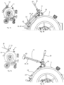
- An unlocked window 14 allows a worker to pivot the window 14 out of the way so that the inner room or inside of the housing 2 can be easily accessed. This is shown in figures 5a and 5b .
- FIGs 5a and 5b illustrate the window 14 pivoted or swivelled away from the opening 10. This leaves the four motion link elements 24 well visible. It can be seen that these motion link elements 24 comprise an entry gap where the projections 26 of the matching projection assembly 18 can enter a motion link or guide rail of the motion link elements 24 for a form-fit locking when the window 14 is manoeuvred into the corresponding position and when the lever 20 is moved towards the housing 2.
- a seal 40 may be arranged on the window 14 so that the inside of the housing 2 is properly sealed off once the window 14 and the window locking mechanism 12 is in the closed position (c.f. figures 3a and 3b ).
- the hinge 28 may be fixed to the opening 10 or it may be fixed to the housing 2.
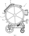
- FIG 6 a cross-sectional view of the inversion unit 1 cut through line VI - VI of figure 1 .
- Figure 6 illustrates an inner space of the housing 2 in which inner space the inner reel 46 is arranged.
- the unlocked position and the open position of the window locking mechanism may be regarded as the same, both positions; the unlocked and open position relate to positions in which the window 14 can be moved out of the way so that the inside of the housing can be accessed.
- the hinge 28 may be connected to an edge of the opening 10 or the housing 2 and it may be fixedly and rigidly connected to one or both of the edge of the opening 10 and the housing 2.
- motion link assembly 16 is shown to have four motion link elements 24, two on each side of the opening 10, and the matching projection assembly 26 has likewise four projections 26, two on each side of the opening 10. Any other symmetric or non-symmetric disposition of projections and motion links may however be used and considered feasible for the invention as explained above.
- the motion link assembly 16 and in particular the guide rails of the motion link assembly 16 may be arranged in a first plane that is oriented perpendicular to a second plane defined by the window 14.
- the matching projection assembly 18 is projecting in a direction perpendicular to the first plane so that the projections 26 can engage in the motion links 24 upon movement of the handle 20 of the window locking mechanism 12.
Landscapes
- Engineering & Computer Science (AREA)
- General Engineering & Computer Science (AREA)
- Mechanical Engineering (AREA)
- Manufacturing & Machinery (AREA)
- Wing Frames And Configurations (AREA)
Claims (11)
- Inversionseinheit, umfassend ein Gehäuse (2), eine Trommel (4) für einen teilweise im Gehäuse (2) angeordneten Liner und eine Basisbaugruppe (6), wobei das Gehäuse (2) an der Basisbaugruppe (6) angeordnet ist, wobei das Gehäuse (2) einen Gaseinlass (36), einen Auslass (8) für den Liner, eine Öffnung (10) umfassend ein Fenster (14) und einen Fensterverriegelungsmechanismus (12) zum Schließen und Öffnen des Fensters (14) umfasst, wobei der Fensterverriegelungsmechanismus (12) dazu ausgestaltet ist, in eine Öffnungsstellung manövriert zu werden, in der das Fenster (14) geöffnet und entriegelt ist, und in eine Schließstellung, in der das Fenster (14) geschlossen und verriegelt ist, dadurch gekennzeichnet, dass der Fensterverriegelungsmechanismus (12) als ein Bajonettverschluss ausgestaltet ist und eine Bewegungsverbindungsbaugruppe (16) und eine passende Vorsprungbaugruppe (18) umfasst, wobei der Fensterverriegelungsmechanismus (12) ferner einen Handgriff (20) und ein Scharnier (28) umfasst, wobei der Handgriff (20) schwenkbar mit dem Scharnier (28) verbunden ist, wobei eine der Bewegungsverbindungsbaugruppe (16) oder der passenden Vorsprungbaugruppe (18) an dem Fenster (14) angeordnet ist oder die andere der passenden Vorsprungbaugruppe (18) oder der Bewegungsverbindungsbaugruppe (16) an einem Rand der Öffnung (10) angeordnet ist, wobei das Scharnier (28) an dem Gehäuse (2) angeordnet ist und wobei der Handgriff (20) schwenkbar mit dem Fenster (14) verbunden ist, sodass das Fenster (14) unter Verwendung des Handgriffs (20) leicht bajonettverschlussartig geöffnet und geschlossen werden kann.
- Inversionseinheit nach Anspruch 1, wobei das Fenster (14) eine Dichtung (40) umfasst, die dazu ausgestaltet ist, die Öffnung (10) abzudichten, wenn sich der Fensterverriegelungsmechanismus (12) in der Schließstellung befindet.
- Inversionseinheit nach Anspruch 1 oder 2, wobei die Öffnung (10) größer ist als der Auslass (8) für den Liner.
- Inversionseinheit nach einem der vorhergehenden Ansprüche, wobei der Handgriff (20) als ein Hebel ausgestaltet ist, der zum Gehäuse (2) hin bewegt werden kann, um den Fensterverriegelungsmechanismus (12) in die Schließstellung zu manövrieren, und der von dem Gehäuse (2) weg bewegt werden kann, um den Fensterverriegelungsmechanismus (12) in eine Öffnungsstellung zu manövrieren.
- Inversionseinheit nach einem der vorhergehenden Ansprüche, wobei das Fenster (14) von der Öffnung (10) weg gedreht werden kann, wenn sich der Fensterverriegelungsmechanismus (12) in seiner Öffnungsstellung befindet.
- Inversionseinheit nach einem der vorhergehenden Ansprüche, wobei die Öffnung im Wesentlichen rechteckig ausgestaltet ist.
- Inversionseinheit nach einem der vorhergehenden Ansprüche, wobei das Gehäuse (2) ferner einen Gasauslass (38) umfasst.
- Inversionseinheit nach einem der vorhergehenden Ansprüche, wobei die Basisbaugruppe (6) von dem Gehäuse (2) getrennt werden kann, und wobei die Basisbaugruppe (6) eine Basis (30) und Räder (32) umfasst.
- Inversionseinheit nach Anspruch 8, wobei die Basisbaugruppe (32) ferner mindestens ein Schwenkrad (34) umfasst.
- Inversionseinheit nach einem der vorhergehenden Ansprüche, wobei das Fenster (14) ferner ein Glas und einen Rahmen (42) umfasst, der das Glas des Fensters (14) einbettet, wobei der Rahmen (42) schwenkbar mit dem Handgriff (20) verbunden ist und der Rahmen (42) die Bewegungsverbindungsbaugruppe (16) oder die passende Vorsprungbaugruppe (18) umfasst.
- Inversionseinheit nach einem der vorhergehenden Ansprüche, wobei die Bewegungsverbindungsbaugruppe (16) in einer ersten Ebene angeordnet ist, die senkrecht zu einer zweiten Ebene ausgerichtet ist, die durch das Fenster (14) definiert ist, und wobei die passende Vorsprungbaugruppe (18) in einer Richtung senkrecht zu der ersten Ebene vorsteht.
Priority Applications (3)
| Application Number | Priority Date | Filing Date | Title |
|---|---|---|---|
| PL23151944.8T PL4403506T3 (pl) | 2023-01-17 | 2023-01-17 | Jednostka inwersyjna z okienkiem |
| EP23151944.8A EP4403506B1 (de) | 2023-01-17 | 2023-01-17 | Inversionseinheit mit fenster |
| US18/484,208 US20240240741A1 (en) | 2023-01-17 | 2023-10-10 | Inversion unit with window |
Applications Claiming Priority (1)
| Application Number | Priority Date | Filing Date | Title |
|---|---|---|---|
| EP23151944.8A EP4403506B1 (de) | 2023-01-17 | 2023-01-17 | Inversionseinheit mit fenster |
Publications (2)
| Publication Number | Publication Date |
|---|---|
| EP4403506A1 EP4403506A1 (de) | 2024-07-24 |
| EP4403506B1 true EP4403506B1 (de) | 2025-05-07 |
Family
ID=84981920
Family Applications (1)
| Application Number | Title | Priority Date | Filing Date |
|---|---|---|---|
| EP23151944.8A Active EP4403506B1 (de) | 2023-01-17 | 2023-01-17 | Inversionseinheit mit fenster |
Country Status (3)
| Country | Link |
|---|---|
| US (1) | US20240240741A1 (de) |
| EP (1) | EP4403506B1 (de) |
| PL (1) | PL4403506T3 (de) |
Family Cites Families (4)
| Publication number | Priority date | Publication date | Assignee | Title |
|---|---|---|---|---|
| DE29700558U1 (de) * | 1997-01-14 | 1997-03-06 | Anton Steinecker Maschinenfabrik GmbH, 85356 Freising | Sudgefäß mit Mannlochöffnung |
| US6733053B2 (en) * | 2002-09-27 | 2004-05-11 | Hodge Products, Inc. | Trash container locking apparatus and method |
| US10550989B2 (en) * | 2017-08-23 | 2020-02-04 | Earth Tool Company Llc | Latch assembly for use with an inversion drum |
| US11204124B2 (en) | 2019-02-17 | 2021-12-21 | Sacpro AB | Inversion unit with expandable carrying handles and removable wheelbase |
-
2023
- 2023-01-17 EP EP23151944.8A patent/EP4403506B1/de active Active
- 2023-01-17 PL PL23151944.8T patent/PL4403506T3/pl unknown
- 2023-10-10 US US18/484,208 patent/US20240240741A1/en active Pending
Also Published As
| Publication number | Publication date |
|---|---|
| EP4403506A1 (de) | 2024-07-24 |
| US20240240741A1 (en) | 2024-07-18 |
| PL4403506T3 (pl) | 2025-06-30 |
Similar Documents
| Publication | Publication Date | Title |
|---|---|---|
| US8851104B2 (en) | Elevating fire hydrant assembly | |
| US10612672B2 (en) | Pipeline control unit | |
| US20100132806A1 (en) | Fire hydrant check valve | |
| US20090145904A1 (en) | Closure for a vessel | |
| CN105986871B (zh) | 排气清理系统、联动阀的应用以及维修方法 | |
| EP4403506A1 (de) | Inversionseinheit mit fenster | |
| US20240309954A1 (en) | Expandable pipe stopper | |
| US8322556B2 (en) | Closure for a vessel | |
| EP3606856B1 (de) | Auskleidungstrommel | |
| US20210129419A1 (en) | Mechanized inverter for pipe liners | |
| US20070215213A1 (en) | Lock valve; a method and system for securing a valve device | |
| JPH043196Y2 (de) | ||
| AU2019204935A1 (en) | A vent for a bitumen tank | |
| US11149875B2 (en) | Lock out device for air actuated valves | |
| EP2787261B1 (de) | In einer Flüssigkeitsverteilungsnetz integriertes Ventil, Netz und Energieumwandlungsinstallation mit solch einem Ventil | |
| ITMI20091491A1 (it) | Impianto mobile per la riparazione e/o la ricostruzione di tubazioni | |
| CN208935837U (zh) | 一种煤气快速切断系统 | |
| WO2017020093A1 (en) | A torque transfer bracket for a large ball valve | |
| US6598850B2 (en) | Butterfly valve locking apparatus | |
| JPH0781669B2 (ja) | 対枝管作業方法および枝管遮閉装置 | |
| EP3517819B1 (de) | Installationsvorrichtung | |
| KR102747185B1 (ko) | 배관 피팅부의 오토 가드 장치 | |
| CN223726093U (zh) | 一种天然气安全防护调压装置 | |
| US20240052609A1 (en) | Hydrant, method for disassembly of a spindle arrangement from a hydrant and method for assembly of a spindle arrangement in a hydrant | |
| US20140273798A1 (en) | Door assembly for a fluid handling system |
Legal Events
| Date | Code | Title | Description |
|---|---|---|---|
| PUAI | Public reference made under article 153(3) epc to a published international application that has entered the european phase |
Free format text: ORIGINAL CODE: 0009012 |
|
| STAA | Information on the status of an ep patent application or granted ep patent |
Free format text: STATUS: THE APPLICATION HAS BEEN PUBLISHED |
|
| AK | Designated contracting states |
Kind code of ref document: A1 Designated state(s): AL AT BE BG CH CY CZ DE DK EE ES FI FR GB GR HR HU IE IS IT LI LT LU LV MC ME MK MT NL NO PL PT RO RS SE SI SK SM TR |
|
| STAA | Information on the status of an ep patent application or granted ep patent |
Free format text: STATUS: REQUEST FOR EXAMINATION WAS MADE |
|
| 17P | Request for examination filed |
Effective date: 20241028 |
|
| RBV | Designated contracting states (corrected) |
Designated state(s): AL AT BE BG CH CY CZ DE DK EE ES FI FR GB GR HR HU IE IS IT LI LT LU LV MC ME MK MT NL NO PL PT RO RS SE SI SK SM TR |
|
| GRAP | Despatch of communication of intention to grant a patent |
Free format text: ORIGINAL CODE: EPIDOSNIGR1 |
|
| STAA | Information on the status of an ep patent application or granted ep patent |
Free format text: STATUS: GRANT OF PATENT IS INTENDED |
|
| RIC1 | Information provided on ipc code assigned before grant |
Ipc: F16J 13/18 20060101ALI20250113BHEP Ipc: B29C 67/00 20170101ALI20250113BHEP Ipc: B29C 63/36 20060101ALI20250113BHEP Ipc: F16L 55/18 20060101ALI20250113BHEP Ipc: B65H 75/44 20060101ALI20250113BHEP Ipc: B65H 75/40 20060101AFI20250113BHEP |
|
| INTG | Intention to grant announced |
Effective date: 20250127 |
|
| GRAS | Grant fee paid |
Free format text: ORIGINAL CODE: EPIDOSNIGR3 |
|
| GRAA | (expected) grant |
Free format text: ORIGINAL CODE: 0009210 |
|
| STAA | Information on the status of an ep patent application or granted ep patent |
Free format text: STATUS: THE PATENT HAS BEEN GRANTED |
|
| AK | Designated contracting states |
Kind code of ref document: B1 Designated state(s): AL AT BE BG CH CY CZ DE DK EE ES FI FR GB GR HR HU IE IS IT LI LT LU LV MC ME MK MT NL NO PL PT RO RS SE SI SK SM TR |
|
| REG | Reference to a national code |
Ref country code: GB Ref legal event code: FG4D |
|
| REG | Reference to a national code |
Ref country code: CH Ref legal event code: EP |
|
| REG | Reference to a national code |
Ref country code: DE Ref legal event code: R096 Ref document number: 602023003239 Country of ref document: DE |
|
| REG | Reference to a national code |
Ref country code: IE Ref legal event code: FG4D |
|
| REG | Reference to a national code |
Ref country code: NL Ref legal event code: MP Effective date: 20250507 |
|
| PG25 | Lapsed in a contracting state [announced via postgrant information from national office to epo] |
Ref country code: FI Free format text: LAPSE BECAUSE OF FAILURE TO SUBMIT A TRANSLATION OF THE DESCRIPTION OR TO PAY THE FEE WITHIN THE PRESCRIBED TIME-LIMIT Effective date: 20250507 Ref country code: ES Free format text: LAPSE BECAUSE OF FAILURE TO SUBMIT A TRANSLATION OF THE DESCRIPTION OR TO PAY THE FEE WITHIN THE PRESCRIBED TIME-LIMIT Effective date: 20250507 Ref country code: PT Free format text: LAPSE BECAUSE OF FAILURE TO SUBMIT A TRANSLATION OF THE DESCRIPTION OR TO PAY THE FEE WITHIN THE PRESCRIBED TIME-LIMIT Effective date: 20250908 |
|
| REG | Reference to a national code |
Ref country code: LT Ref legal event code: MG9D |
|
| PG25 | Lapsed in a contracting state [announced via postgrant information from national office to epo] |
Ref country code: GR Free format text: LAPSE BECAUSE OF FAILURE TO SUBMIT A TRANSLATION OF THE DESCRIPTION OR TO PAY THE FEE WITHIN THE PRESCRIBED TIME-LIMIT Effective date: 20250808 |
|
| PG25 | Lapsed in a contracting state [announced via postgrant information from national office to epo] |
Ref country code: NL Free format text: LAPSE BECAUSE OF FAILURE TO SUBMIT A TRANSLATION OF THE DESCRIPTION OR TO PAY THE FEE WITHIN THE PRESCRIBED TIME-LIMIT Effective date: 20250507 |
|
| REG | Reference to a national code |
Ref country code: AT Ref legal event code: MK05 Ref document number: 1792313 Country of ref document: AT Kind code of ref document: T Effective date: 20250507 |
|
| PG25 | Lapsed in a contracting state [announced via postgrant information from national office to epo] |
Ref country code: BG Free format text: LAPSE BECAUSE OF FAILURE TO SUBMIT A TRANSLATION OF THE DESCRIPTION OR TO PAY THE FEE WITHIN THE PRESCRIBED TIME-LIMIT Effective date: 20250507 |
|
| PG25 | Lapsed in a contracting state [announced via postgrant information from national office to epo] |
Ref country code: HR Free format text: LAPSE BECAUSE OF FAILURE TO SUBMIT A TRANSLATION OF THE DESCRIPTION OR TO PAY THE FEE WITHIN THE PRESCRIBED TIME-LIMIT Effective date: 20250507 |
|
| PG25 | Lapsed in a contracting state [announced via postgrant information from national office to epo] |
Ref country code: AT Free format text: LAPSE BECAUSE OF FAILURE TO SUBMIT A TRANSLATION OF THE DESCRIPTION OR TO PAY THE FEE WITHIN THE PRESCRIBED TIME-LIMIT Effective date: 20250507 |
|
| PG25 | Lapsed in a contracting state [announced via postgrant information from national office to epo] |
Ref country code: RS Free format text: LAPSE BECAUSE OF FAILURE TO SUBMIT A TRANSLATION OF THE DESCRIPTION OR TO PAY THE FEE WITHIN THE PRESCRIBED TIME-LIMIT Effective date: 20250807 |
|
| PG25 | Lapsed in a contracting state [announced via postgrant information from national office to epo] |
Ref country code: IS Free format text: LAPSE BECAUSE OF FAILURE TO SUBMIT A TRANSLATION OF THE DESCRIPTION OR TO PAY THE FEE WITHIN THE PRESCRIBED TIME-LIMIT Effective date: 20250907 |
|
| PG25 | Lapsed in a contracting state [announced via postgrant information from national office to epo] |
Ref country code: LV Free format text: LAPSE BECAUSE OF FAILURE TO SUBMIT A TRANSLATION OF THE DESCRIPTION OR TO PAY THE FEE WITHIN THE PRESCRIBED TIME-LIMIT Effective date: 20250507 |
|
| PG25 | Lapsed in a contracting state [announced via postgrant information from national office to epo] |
Ref country code: DK Free format text: LAPSE BECAUSE OF FAILURE TO SUBMIT A TRANSLATION OF THE DESCRIPTION OR TO PAY THE FEE WITHIN THE PRESCRIBED TIME-LIMIT Effective date: 20250507 Ref country code: SM Free format text: LAPSE BECAUSE OF FAILURE TO SUBMIT A TRANSLATION OF THE DESCRIPTION OR TO PAY THE FEE WITHIN THE PRESCRIBED TIME-LIMIT Effective date: 20250507 |
|
| PG25 | Lapsed in a contracting state [announced via postgrant information from national office to epo] |
Ref country code: CZ Free format text: LAPSE BECAUSE OF FAILURE TO SUBMIT A TRANSLATION OF THE DESCRIPTION OR TO PAY THE FEE WITHIN THE PRESCRIBED TIME-LIMIT Effective date: 20250507 |
|
| PG25 | Lapsed in a contracting state [announced via postgrant information from national office to epo] |
Ref country code: EE Free format text: LAPSE BECAUSE OF FAILURE TO SUBMIT A TRANSLATION OF THE DESCRIPTION OR TO PAY THE FEE WITHIN THE PRESCRIBED TIME-LIMIT Effective date: 20250507 |
|
| PG25 | Lapsed in a contracting state [announced via postgrant information from national office to epo] |
Ref country code: SK Free format text: LAPSE BECAUSE OF FAILURE TO SUBMIT A TRANSLATION OF THE DESCRIPTION OR TO PAY THE FEE WITHIN THE PRESCRIBED TIME-LIMIT Effective date: 20250507 |
|
| PG25 | Lapsed in a contracting state [announced via postgrant information from national office to epo] |
Ref country code: IT Free format text: LAPSE BECAUSE OF FAILURE TO SUBMIT A TRANSLATION OF THE DESCRIPTION OR TO PAY THE FEE WITHIN THE PRESCRIBED TIME-LIMIT Effective date: 20250507 |
|
| REG | Reference to a national code |
Ref country code: DE Ref legal event code: R097 Ref document number: 602023003239 Country of ref document: DE |
|
| PLBE | No opposition filed within time limit |
Free format text: ORIGINAL CODE: 0009261 |
|
| STAA | Information on the status of an ep patent application or granted ep patent |
Free format text: STATUS: NO OPPOSITION FILED WITHIN TIME LIMIT |
|
| REG | Reference to a national code |
Ref country code: CH Ref legal event code: L10 Free format text: ST27 STATUS EVENT CODE: U-0-0-L10-L00 (AS PROVIDED BY THE NATIONAL OFFICE) Effective date: 20260318 |
|
| PGFP | Annual fee paid to national office [announced via postgrant information from national office to epo] |
Ref country code: NO Payment date: 20260126 Year of fee payment: 4 |
|
| 26N | No opposition filed |
Effective date: 20260210 |