EP0849461B1 - Verbrennungsregler für Brennkraftmaschine - Google Patents
Verbrennungsregler für Brennkraftmaschine Download PDFInfo
- Publication number
- EP0849461B1 EP0849461B1 EP97122395A EP97122395A EP0849461B1 EP 0849461 B1 EP0849461 B1 EP 0849461B1 EP 97122395 A EP97122395 A EP 97122395A EP 97122395 A EP97122395 A EP 97122395A EP 0849461 B1 EP0849461 B1 EP 0849461B1
- Authority
- EP
- European Patent Office
- Prior art keywords
- engine
- combustion mode
- fuel
- ecu
- charge combustion
- Prior art date
- Legal status (The legal status is an assumption and is not a legal conclusion. Google has not performed a legal analysis and makes no representation as to the accuracy of the status listed.)
- Expired - Lifetime
Links
Images

Classifications
-
- F—MECHANICAL ENGINEERING; LIGHTING; HEATING; WEAPONS; BLASTING
- F02—COMBUSTION ENGINES; HOT-GAS OR COMBUSTION-PRODUCT ENGINE PLANTS
- F02D—CONTROLLING COMBUSTION ENGINES
- F02D41/00—Electrical control of supply of combustible mixture or its constituents
- F02D41/30—Controlling fuel injection
- F02D41/32—Controlling fuel injection of the low pressure type
- F02D41/34—Controlling fuel injection of the low pressure type with means for controlling injection timing or duration
-
- F—MECHANICAL ENGINEERING; LIGHTING; HEATING; WEAPONS; BLASTING
- F02—COMBUSTION ENGINES; HOT-GAS OR COMBUSTION-PRODUCT ENGINE PLANTS
- F02D—CONTROLLING COMBUSTION ENGINES
- F02D41/00—Electrical control of supply of combustible mixture or its constituents
- F02D41/30—Controlling fuel injection
- F02D41/3011—Controlling fuel injection according to or using specific or several modes of combustion
- F02D41/3064—Controlling fuel injection according to or using specific or several modes of combustion with special control during transition between modes
- F02D41/307—Controlling fuel injection according to or using specific or several modes of combustion with special control during transition between modes to avoid torque shocks
-
- F—MECHANICAL ENGINEERING; LIGHTING; HEATING; WEAPONS; BLASTING
- F02—COMBUSTION ENGINES; HOT-GAS OR COMBUSTION-PRODUCT ENGINE PLANTS
- F02D—CONTROLLING COMBUSTION ENGINES
- F02D41/00—Electrical control of supply of combustible mixture or its constituents
- F02D41/30—Controlling fuel injection
- F02D41/3011—Controlling fuel injection according to or using specific or several modes of combustion
- F02D41/3017—Controlling fuel injection according to or using specific or several modes of combustion characterised by the mode(s) being used
- F02D41/3023—Controlling fuel injection according to or using specific or several modes of combustion characterised by the mode(s) being used a mode being the stratified charge spark-ignited mode
- F02D41/3029—Controlling fuel injection according to or using specific or several modes of combustion characterised by the mode(s) being used a mode being the stratified charge spark-ignited mode further comprising a homogeneous charge spark-ignited mode
-
- Y—GENERAL TAGGING OF NEW TECHNOLOGICAL DEVELOPMENTS; GENERAL TAGGING OF CROSS-SECTIONAL TECHNOLOGIES SPANNING OVER SEVERAL SECTIONS OF THE IPC; TECHNICAL SUBJECTS COVERED BY FORMER USPC CROSS-REFERENCE ART COLLECTIONS [XRACs] AND DIGESTS
- Y02—TECHNOLOGIES OR APPLICATIONS FOR MITIGATION OR ADAPTATION AGAINST CLIMATE CHANGE
- Y02T—CLIMATE CHANGE MITIGATION TECHNOLOGIES RELATED TO TRANSPORTATION
- Y02T10/00—Road transport of goods or passengers
- Y02T10/10—Internal combustion engine [ICE] based vehicles
- Y02T10/12—Improving ICE efficiencies
-
- Y—GENERAL TAGGING OF NEW TECHNOLOGICAL DEVELOPMENTS; GENERAL TAGGING OF CROSS-SECTIONAL TECHNOLOGIES SPANNING OVER SEVERAL SECTIONS OF THE IPC; TECHNICAL SUBJECTS COVERED BY FORMER USPC CROSS-REFERENCE ART COLLECTIONS [XRACs] AND DIGESTS
- Y02—TECHNOLOGIES OR APPLICATIONS FOR MITIGATION OR ADAPTATION AGAINST CLIMATE CHANGE
- Y02T—CLIMATE CHANGE MITIGATION TECHNOLOGIES RELATED TO TRANSPORTATION
- Y02T10/00—Road transport of goods or passengers
- Y02T10/10—Internal combustion engine [ICE] based vehicles
- Y02T10/40—Engine management systems
Definitions
- the present invention relates to combustion controllers for internal combustion engines that shift combustion modes in accordance with the operating conditions of the engine.
- fuel is injected into an intake port by a fuel injector to charge the associated combustion chamber with a homogeneous mixture of fuel and air.
- An air intake passage is opened and closed by a throttle valve, which is operated in cooperation with an acceleration pedal. The opening of the throttle valve adjusts the intake air amount (and ultimately the amount of homogeneously mixed air and fuel) that is supplied to the combustion chambers of the engine. This controls engine power.
- the combustion of the air fuel mixture in such homogeneous state is normally referred to as homogeneous charge combustion.
- the throttling action of the throttle valve decreases the pressure in the intake passage. This increases energy loss due to pumping (pumping loss) when the air fuel mixture is drawn into the combustion chambers from the intake passage and thus decreases the efficiency of the engine.
- This problem can be dealt with by direct injection.
- the throttle valve In an engine that performs direct injection, the throttle valve is opened wide and fuel is injected directly into each combustion chamber. The air drawn into each combustion chamber is swirled and mixed with atomized fuel to form a stratum of a stoichiometric air-fuel mixture near the spark plug.
- stratified charge combustion increases the overall air-fuel ratio of the mixture that is burned. This improves fuel efficiency.
- Stratified charge combustion is the optimal combustion mode if the engine is in a low speed range or intermediate speed range, and the amount of fuel injection is thus small, In comparison, homogeneous charge combustion is the optimal combustion mode if the engine is in a high speed range, and the amount of fuel injection is thus great. Therefore, it is beneficial for an engine to perform both stratified charge combustion and homogeneous charge combustion.
- Japanese Unexamined Patent Publication No. 5-52145 describes an engine that shifts combustion modes (or fuel injection modes) between stratified charge combustion, homogeneous charge combustion, and semi-stratified charge combustion.
- Stratified charge combustion is performed when the load applied to the engine is light. In this mode, fuel is injected during the compression stroke. If a heavy load is applied to the engine, homogeneous charge combustion is performed. In this mode, fuel is injected during the intake stroke. If an intermediate load is applied to the engine, semi-stratified charge combustion is performed. In this mode, fuel is injected twice, once during the intake stroke and once during the compression stroke.
- the shifting of the combustion mode, or the fuel injection mode results in certain problems.
- the combustion mode is shifted from stratified charge combustion to homogeneous charge combustion, the amount of fuel injection is increased.
- the intake air is throttled by the throttle valve. This results in energy loss (pumping loss) and decreases the engine torque in a sudden manner. It is preferable for the torque to increase gradually as the engine load increases.
- the fuel injection is determined in accordance with changes in the engine load without taking pumping losses into consideration, sudden torque fluctuations will occur when switching the combustion mode.
- the present invention provides an apparatus for controlling fuel injection according to a combustion mode of an engine selected from a combustion mode group including a stratified charge combustion mode and a homogeneous charge combustion mode.
- the apparatus includes a nozzle for injecting fuel to an engine.
- a detecting means detects the driving state of the engine.
- a first computing means computes a basic amount of the injection fuel that is injected from the nozzle based on the detected driving state of the engine.
- a switching means switches the combustion mode based on the computed basic amount.
- a second computing means computes a corrected amount of the injection fuel based on the basic amount of the injection fuel.
- the corrected amount of the injection fuel suppresses a fluctuation of engine torque caused by switching of the combustion mode.
- a controlling means controls the nozzle based on the corrected amount of the injection fuel in synchronism with switching of the combustion mode.
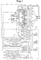
- Fig. 1 is a schematic view showing a combustion control apparatus of an automotive engine that injects fuel directly into its cylinders (direct injection type engine).
- An engine 1 has, for example, four cylinders 1a.
- the structure of the combustion chamber of each cylinder 1a is shown in Fig. 2.
- the engine 1 has a cylinder block 2 that houses the cylinders 1a.
- Each cylinder 1a accommodates a piston.
- a cylinder head 4 is arranged on top of the cylinder block 2.
- a combustion chamber 5 is defined between each piston and the cylinder head 4.
- Four valves (first intake valve 6a, second intake valve 6b, and two exhaust valves 8) are provided for each cylinder 1a.
- the first intake valve 6a is connected with a first intake port 7a while the second intake valve 6b is connected with a second intake port 7b.
- Each exhaust valve 8 is connected with an exhaust port 9.
- the first intake port 7a is a helical port that extends in a helical manner.
- the second intake port 7b extends in a generally straight manner.
- Spark plugs 10 are arranged at the middle of the cylinder head 4. High voltage is applied to each spark plug 10 by an ignitor 12 through a distributor (not shown). The ignition timing of each spark plug 10 is determined by the output timing of the high voltage sent from the ignitor 12.
- a fuel injector 11 is arranged near the inner wall of the cylinder head at the vicinity of each set of first and second intake valves 6a, 6b. The fuel injector 11 is used to inject fuel directly into the associated cylinder 1a.
- the first and second intake ports 7a, 7b of each cylinder 1a are connected to a surge tank 16 by a first intake passage 15a and a second intake passage 15b, which are defined in an intake manifold 15.
- a swirl control valve 17 is arranged in each second intake passage 15b.
- the swirl control valves 17 are connected to, for example, a step motor 19 by a common shaft 18.
- the step motor 19 is controlled by signals sent from an electronic control unit (ECU) 30.
- the swirl control valves 17 may be driven by the pressure in the associated first and second intake ports 7a, 7b instead of by the step motor 19.
- the surge tank 16 is connected to an air cleaner 21 through an intake duct 20.
- the ECU 30 sends signals to drive the step motor 22 and open and close the throttle valve 23.
- the throttle valve 23 adjusts the amount of intake air that passes through the intake duct 20 and enters the combustion chambers 5.
- a throttle sensor 25 is arranged in the vicinity of the throttle valve 23 to detect the opening angle (throttle angle TA) of the valve 23.
- the exhaust ports 9 of each cylinder 1a are connected to an exhaust manifold 14. After combustion, the exhaust gas is sent to an exhaust duct (not shown) through the exhaust manifold 14.
- a conventional exhaust gas recirculation (EGR) mechanism 51 recirculates some of the exhaust gas through an EGR passage 52.
- An EGR valve 53 is arranged in the EGR passage 52.
- the EGR passage 52 connects the downstream side of the throttle valve 23 in the intake duct 20 to the exhaust duct.
- the EGR valve 53 includes a valve seat, a valve body, and a step motor (none of which is shown). The opening area of the EGR valve 53 is altered by causing the step motor to intermittently displace the valve body with respect to the valve seat.
- EGR amount is adjusted by the opening amount of the EGR valve 53 (EGR valve opening EGRV).
- the ECU 30 is a digital computer provided with a random access memory (RAM) 32, a read only memory (ROM) 33, a central processing unit (CPU) 34, which is a microprocessor, an input port 35, and an output port 36 that are connected to one another by a bidirectional bus 31.
- RAM random access memory
- ROM read only memory
- CPU central processing unit
- An acceleration pedal 24 is connected to an acceleration sensor 26A.
- the acceleration sensor 26A generates voltage proportional to the depression degree of the acceleration pedal 24 and detects the acceleration pedal depression degree ACCP.
- the voltage output by the acceleration sensor 26A is input into the input port 35 by way of an analog to digital (A/D) converter 37.
- the acceleration pedal 24 is also provided with a complete closure switch 26B to detect when the pedal 24 is not depressed at all.
- the closure switch 26B outputs a complete closure signal of one when the acceleration pedal 24 is not depressed at all and outputs a complete closure signal of zero when the acceleration pedal 24 is depressed.
- the output voltage of the closure switch 26B is also input to the input port 35.
- a top dead center position sensor 27 generates an output pulse when, for example, the piston in cylinder the first cylinder 1a reaches the top dead center position during the intake stroke.
- the output pulse is input to the input port 35.
- a crank angle sensor 28 generates an output pulse, which is input to the input port 35, each time a crankshaft of the engine 1 is rotated by a crank angle CA of 30 degrees.
- the CPU 34 reads the output pulses sent from the top dead center position sensor 27 and the crank angle sensor 28 to compute the engine speed NE.
- the rotational angle of the shaft 18 is detected by a swirl control valve sensor 29 to measure the opening angle of the swirl control valves 17 (swirl control valve angle SCV).
- the signal output of the swirl control valve sensor 29 is input to the input port 35 by way of an A/D converter 37.
- the throttle sensor 25 detects the throttle angle TA.
- the signal output of the throttle sensor 25 is input to the input port 35 by way of an A/D converter 37.
- An intake pressure sensor 61 is provided to detect the pressure in the surge tank 16 (intake pressure PiM).
- a coolant temperature sensor 62 is provided in the engine 1 to detect the temperature of the engine coolant (coolant temperature THW). The signal outputs of the sensors 61, 62 are input to the input port 35 by way of A/D converters 37.
- the operating conditions of the engine 1 are detected by the throttle sensor 25, the acceleration sensor 26A, the complete closure switch 26B, the top dead center position sensor 27, the crank angle sensor 28, the swirl control valve sensor 29, the intake pressure sensor 61, and the coolant temperature sensor 62.
- the output port 36 is connected to the fuel injectors 11, the step motors 19, 22, the ignitor 12, and the step motor of the EGR valve 53 by way of drive circuits 38.
- the ECU 30 controls the fuel injectors 11, the step motors 19, 22, the ignitor 12, and the EGR valve 53 with control programs stored in the ROM 33 based on signals sent from the sensors 25-29 and 61-62.
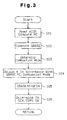
- a routine executed by the ECU 30 to control the amount of fuel injection is illustrated in the flow chart of Fig. 3.
- the ECU 30 executes this routine in an interrupting manner once for every predetermined crank angle.
- the ECU 30 When entering this routine, at step 101, the ECU 30 reads the signals that indicate the acceleration pedal depression degree ACCP. The ECU 30 also reads the signals sent from the top dead center position sensor 27 and the crank angle sensor 28 to compute the engine speed NE.
- the ECU 30 obtains the basic fuel injection amount QBASE from a basic fuel injection map (not shown) in accordance with the acceleration pedal depression degree ACCP and the engine speed NE.
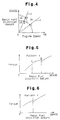
- the ECU 30 determines the appropriate combustion mode corresponding to the basic fuel injection amount QBASE and the engine speed NE by referring to a map shown in Fig. 4.
- the combustion mode is selected from stratified charge combustion, semi-stratified charge combustion, and homogeneous charge combustion.
- the map of Fig. 4 illustrates the appropriate combustion mode with respect to the basic fuel injection amount QBASE and the engine speed NE.
- the range indicated by (1) corresponds to stratified charge combustion.
- Range (1) is the area beneath the lower curve.
- the range indicated by (2) corresponds to semi-stratified charge combustion.
- Range (2) is the area between the upper and lower curves.
- the range indicated by (3) corresponds to homogeneous charge combustion.
- Range (3) is the area outside of areas (1) and (2).
- Each combustion mode range is determined based on the torque fluctuations produced in correspondence with the basic fuel injection amount QBASE.
- stratified charge combustion fuel is injected during the compression stroke.
- homogeneous charge combustion fuel is injected during the intake stroke.
- semi-stratified charge combustion fuel is injected twice, once during the compression stroke and once during the intake stroke.
- the lines denoted as ⁇ and ⁇ each show different patterns that. appear when the basic fuel injection amount QBASE is increased or decreased in a proportional manner with respect to the engine speed NE.
- Line ⁇ represents a pattern in which the increasing ratio of the engine speed NE with respect to the engine load is small, such as when the automobile is climbing a slope.
- Line ⁇ represents a pattern in which the increasing ratio of the engine speed NE is greater than that of line ⁇ .
- stratified charge combustion is performed when the basic fuel injection amount QBASE is relatively small. As the basic fuel injection amount QBASE increases, the combustion mode is shifted to semi-stratified charge combustion and then to homogeneous charge combustion.
- pattern ⁇ stratified charge combustion is performed when the basic fuel injection amount QBASE is relatively small. As the basic fuel injection amount QBASE increases, the combustion mode is shifted directly to homogenous charge combustion from stratified charge combustion. In other words, semi-stratified charge combustion is not performed.
- the sudden torque increase that occurs at combustion mode shifting point A is caused by the slight difference that always exists between the basic fuel injection amount QBASE and the amount of fuel actually burned (actual fuel injection amount). Shifting of the combustion mode results in a sudden change in the difference between the basic fuel injection amount QBASE and the actual fuel injection amount. The sudden difference change may cause torque fluctuation. At shifting point A, the sudden change in the injection amount difference becomes greater than the influence of pumping loss and causes the sudden torque increase.
- the routine shown in the flow chart of Fig. 3 suppresses torque fluctuations during the shifting of combustion modes.
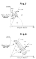
- the ECU 30 proceeds to step 104 from step 103 and obtains a fuel injection correction coefficient K based on the basic fuel injection amount QBASE and the engine speed NE.
- the ECU 30 refers to maps shown in Figs. 7 and 8.
- the correction coefficient K is used to correct the basic fuel injection amount QBASE and reduce torque fluctuations that occur, especially when the combustion mode, or fuel injection mode, is shifted. Pumping losses and the difference between the basic fuel injection amount QBASE and the actual fuel injection amount are taken into consideration by the correction coefficient K.
- the map of Fig. 7 is referred to when semi-stratified charge combustion is performed, and the map of Fig.
- the correction coefficient K varies with respect to the basic fuel injection amount QBASE and the engine speed NE as shown in each map.
- the correction coefficient K differs between engines having different characteristics. In the preferred embodiment, the correction coefficient ranges from 0.95 to 1.20.
- the value of the correction coefficient K during stratified charge combustion is fixed at one. In other words, the fuel injection amount QBASE is not corrected when the stratified charge combustion is performed.
- the range indicated by (1) corresponds to stratified charge combustion
- the range indicated by (2) corresponds to semi-stratified charge combustion
- the range indicated by (3) corresponds to homogeneous charge combustion.
- the lines denoted by ⁇ and ⁇ correspond to patterns ⁇ and ⁇ shown in Figs. 4 to 6.
- the maps of both Figs. 7 and 8 show the relationship between the engine speed NE and the basic fuel injection amount QBASE with respect to the correction coefficient K during any given condition of the engine 1 in the associated combustion mode.
- the ECU 30 actually determines the correction coefficient K from the semi-stratified charge range (2) when referring to the map of Fig. 7, and from the homogeneous charge range (3) when referring to the map of Fig. 8.
- the correction coefficient K is determined in the following manner:
- the correction coefficient K is determined in the same manner as pattern ⁇ . Therefore, as shown in Fig. 8, the basic fuel injection amount QBASE is corrected to a larger value when the engine 1 shifts from stratified charge combustion to homogeneous charge combustion at shifting point C (Fig. 6).
- the value of the correction coefficient K is larger at the boundary between the homogeneous charge combustion range (3) and the stratified charge combustion range (1) than the boundary between the homogeneous charge combustion range (3) and the semi-stratified charge combustion range (2).
- the correction coefficient K is smaller than one in the semi-stratified charge combustion range (2).
- the correction coefficient K corrects the basic fuel injection amount QBASE to a relatively large value when the engine 1 shifts from the stratified charge combustion mode (1) to the homogeneous charge combustion mode (3).
- the ECU 30 computes a target fuel injection amount QFIN by multiplying the current basic fuel injection amount QBASE with the fuel injection correction coefficient K.
- the ECU 30 then proceeds to step 106 and determines the throttle angle TA, the swirl control valve angle SCV, the EGR valve opening EGRV, and the ignition timing SA. Afterwards, the ECU 30 terminates subsequent processing.
- the target fuel injection amount QFIN which is obtained by correcting the basic fuel injection amount QBASE with the correction coefficient K, suppresses sudden torque fluctuations during both pattern ⁇ and pattern ⁇ , as shown by the dotted line in Figs. 5 and 6.
- the preferred and illustrated embodiment prevents sudden torque fluctuations by correcting the basic fuel injection amount QBASE and adjusting the actual amount of fuel injection when shifting combustion modes.
- the correction coefficient K for correcting the fuel injection amount is predetermined and not determined by feedback control. This effectively prevents torque fluctuations before they occur.
- torque fluctuations are suppressed by correcting the basic fuel injection amount QBASE.
- the combustion mode shifting point which corresponds to the engine load and the operating conditions of the engine, is not altered.
- the optimal torque curve in correspondence with the combustion mode is achieved. This improves the driving performance of the engine.
- the preferred and illustrated embodiment is applied to an engine 1 that injects fuel directly into the cylinders.
- the present invention may be applied to any other type of engine that shifts the combustion mode between stratified charge combustion and homogeneous charge combustion.
- the present invention may be applied to an engine that injects fuel toward the stems of the valve heads of the intake valves 6a, 6b.
- each fuel injector 11 injects fuel near each set of first and second intake valves 6a, 6b.
- fuel injection may be carried out by employing injectors that inject fuel directly into the associated cylinder together with injectors that inject fuel outside the combustion chambers 5.
- helical type intake ports are employed to produce swirls.
- the swirls do not necessarily have to be produced.
- parts such as the swirl control valve 17 and the step motor 19 may be eliminated.
- the preferred and illustrated embodiment is applied to a gasoline engine.
- the present invention may also be applied to other types of engines such as diesel engines.
- An engine (1) operates in a stratified charge combustion mode and a homogeneous charge combustion mode.
- a sensor detects driving state of the engine.
- An ECU electronic control unit (30) computes a basic amount of the fuel to be injected from a nozzle (11) based on the detected driving state of the engine.
- the ECU switches the combustion mode based on the computed basic amount.
- the ECU computes a corrected amount of the injection fuel based on the basic amount of the injection fuel.
- the corrected amount of the injection fuel suppresses a fluctuation of engine torque caused by switching of the combustion mode.
- the ECU controls the injection valve based on the computed corrected amount.
Claims (8)
- Gerät, das Kraftstoffeinspritzung gemäß einem Verbrennungsmodus einer Kraftmaschine (1) steuert, das eine Düse (11) zum Einspritzen von Kraftstoff zu einer Kraftmaschine (1) hat, wobei eine Grundmenge des einzuspritzenden Kraftstoffs durch eine elektronische Steuereinheit (ECU) (30) auf Grundlage eines Betriebszustands der Kraftmaschine (1) berechnet wird und wobei der Verbrennungsmodus durch die ECU(30) aus einer Verbrennungsmodusgruppe ausgewählt wird, die einen geschichteten Ladungsverbrennungsmodus und einen homogenen Ladungsverbrennungsmodus beinhaltet, wobei das Gerät
dadurch gekennzeichnet ist, dass
die ECU (30) den Verbrennungsmodus auf Grundlage der berechneten Grundmenge umschaltet, eine Korrekturmenge des Einspritzkraftstoffs auf Grundlage der Grundmenge des Einspritzkraftstoffs berechnet, wobei die korrigierte Menge des Einspritzkraftstoffs eine durch Umschalten des Verbrennungsmodus verursachte Kraftmaschinendrehmomentschwankung unterdrückt und die Einspritzdüse (11) auf Grundlage des korrigierten Einspritzkraftstoffs im Gleichlauf mit Umschalten des Verbrennungsmodus steuert. - Gerät gemäß Anspruch 1,
dadurch gekennzeichnet, dass
die ECU(30) einen Korrekturwert zum Berechnen der korrigierten Menge des Einspritzkraftstoffs auf Grundlage der Grundmenge des Einspritzkraftstoffs berechnet. - Gerät gemäß Anspruch 2,
dadurch gekennzeichnet, dass
die ECU (30) den Wert "1" für den Korrekturwert auswählt, wenn die Kraftmaschine (1) in dem geschichteten Ladungsverbrennungsmodus arbeitet und die ECU (30) einen Wert größer als "1" als den Korrekturwert setzt, wenn die Kraftmaschine (1) in dem homogenen Ladungsverbrennungsmodus arbeitet. - Gerät gemäß Anspruch 3,
dadurch gekennzeichnet, dass
die Düse (11) den Kraftstoff in Verbindung mit einem Verdichtungstakt eines Kolbens einspritzt, wenn die Kraftmaschine (1) in dem geschichteten Ladungsverbrennungsmodus arbeitet und wobei die Düse (11) den Kraftstoff in Verbindung mit einem Ansaugtakt des Kolbens einspritzt, wenn die Kraftmaschine (1) in dem homogenen Ladungsverbrennungsmodus arbeitet. - Gerät gemäß Anspruch 2,
dadurch gekennzeichnet, dass
die Verbrennungsmodusgruppe einen halbgeschichteten Ladungsverbrennungsmodus beinhaltet, wobei die ECU (30) einen Wert, der kleiner als "1" ist, als den Korrekturwert setzt, wenn die Kraftmaschine (1) in dem halbgeschichteten Ladungsverbrennungsmodus arbeitet und wobei die Düse (11) den Kraftstoff bei Teilung in zwei Portionen jeweils in Verbindung mit dem Verdichtungstakt bzw. dem Ansaugtakt des Kolbens einspritzt, wenn die Kraftmaschine (1) in dem halbgeschichteten Ladungsverbrennungsmodus arbeitet. - Gerät gemäß einem der vorangehenden Ansprüche,
dadurch gekennzeichnet, dass
die Kraftmaschine einen Lufteinlassdurchlass (15a, 15b, 16, 20) zum Einführen von Luft zu einer Verbrennungskammer (5) hat, wobei der durch die Düse eingespritzte Kraftstoff und die Luft ein Gemisch in der Verbrennungskammer (5) ausbilden. - Gerät gemäß Anspruch 7,
gekennzeichnet durch
ein Drosselventil (23), das in dem Lufteinlassdurchlass angeordnet ist, um die Luftströmung in dem Einlassdurchlass zu beschränken. - Gerät gemäß Anspruch 8,
gekennzeichnet durch
einen Elektromotor (22), der das Drosselventil (23) in Erwiederung auf eine Anweisung von der ECU(30) betätigt.
Applications Claiming Priority (3)
| Application Number | Priority Date | Filing Date | Title |
|---|---|---|---|
| JP33978396 | 1996-12-19 | ||
| JP33978396 | 1996-12-19 | ||
| JP339783/96 | 1996-12-19 |
Publications (3)
| Publication Number | Publication Date |
|---|---|
| EP0849461A2 EP0849461A2 (de) | 1998-06-24 |
| EP0849461A3 EP0849461A3 (de) | 1999-11-10 |
| EP0849461B1 true EP0849461B1 (de) | 2003-03-12 |
Family
ID=18330774
Family Applications (1)
| Application Number | Title | Priority Date | Filing Date |
|---|---|---|---|
| EP97122395A Expired - Lifetime EP0849461B1 (de) | 1996-12-19 | 1997-12-18 | Verbrennungsregler für Brennkraftmaschine |
Country Status (3)
| Country | Link |
|---|---|
| US (1) | US5896840A (de) |
| EP (1) | EP0849461B1 (de) |
| DE (1) | DE69719704T2 (de) |
Families Citing this family (26)
| Publication number | Priority date | Publication date | Assignee | Title |
|---|---|---|---|---|
| FR2758590B1 (fr) * | 1997-01-20 | 1999-04-16 | Siemens Automotive Sa | Dispositif de commande d'un moteur a combustion interne a allumage commande et injection directe |
| JP3680491B2 (ja) * | 1997-06-02 | 2005-08-10 | 日産自動車株式会社 | 内燃機関の制御装置 |
| DE69825682T2 (de) * | 1997-06-25 | 2005-01-13 | Nissan Motor Co., Ltd., Yokohama | Steuervorrichtung einer direkteinspritzenden Otto-Brennkraftmaschine |
| JPH1122531A (ja) * | 1997-06-30 | 1999-01-26 | Unisia Jecs Corp | 直噴火花点火式内燃機関の制御装置 |
| DE69832130T2 (de) * | 1997-07-04 | 2006-04-20 | Nissan Motor Co., Ltd., Yokohama | Steuerungssystem für eine Brennkraftmaschine |
| JP3508481B2 (ja) * | 1997-07-08 | 2004-03-22 | 日産自動車株式会社 | 内燃機関の制御装置 |
| DE19813378A1 (de) * | 1998-03-26 | 1999-10-07 | Bosch Gmbh Robert | Verfahren zum Betreiben einer Brennkraftmaschine |
| US5947079A (en) * | 1998-06-08 | 1999-09-07 | Ford Global Technologies, Inc. | Mode control system for direct injection spark ignition engines |
| DE19833830A1 (de) * | 1998-07-28 | 2000-02-03 | Bosch Gmbh Robert | Verfahren und Vorrichtung zur Steuerung wenigstens eines Magnetventils |
| US6978764B1 (en) | 1999-10-18 | 2005-12-27 | Ford Global Technologies, Inc. | Control method for a vehicle having an engine |
| US6470869B1 (en) * | 1999-10-18 | 2002-10-29 | Ford Global Technologies, Inc. | Direct injection variable valve timing engine control system and method |
| US6560527B1 (en) * | 1999-10-18 | 2003-05-06 | Ford Global Technologies, Inc. | Speed control method |
| US7398762B2 (en) * | 2001-12-18 | 2008-07-15 | Ford Global Technologies, Llc | Vehicle control system |
| US6712041B1 (en) * | 1999-10-18 | 2004-03-30 | Ford Global Technologies, Inc. | Engine method |
| US7299786B2 (en) | 2004-02-05 | 2007-11-27 | Ford Global Technologies Llc | Vehicle control system |
| US6390054B1 (en) | 2000-08-26 | 2002-05-21 | Ford Global Technologies, Inc. | Engine control strategy for a hybrid HCCI engine |
| DE10048238B4 (de) * | 2000-09-29 | 2014-09-18 | Daimler Ag | Verfahren zum Betrieb einer Dieselbrennkraftmaschine |
| US6736105B1 (en) | 2002-10-29 | 2004-05-18 | Ford Global Technologies, Llc | Control system for direct injection spark ignition engines with a cam profile switching device |
| US7021276B2 (en) * | 2004-03-25 | 2006-04-04 | International Engine Intellectual Property Company, Llc | Control strategy for HCCI-CD combustion in a diesel engine using two fuel injection phases |
| US6957640B1 (en) | 2004-06-23 | 2005-10-25 | International Engine Intellectual Property Company, Llc | Strategy for fueling a diesel engine by selective use of fueling maps to provide HCCI+RVT, HCCI+VVT, and CD+RVT combustion modes |
| US20050284441A1 (en) * | 2004-06-23 | 2005-12-29 | Zhengbai Liu | Strategy for fueling a diesel engine by selective use of fueling maps to provide HCCI, HCCI+CD, and CD combustion modes |
| US7461627B2 (en) * | 2006-04-27 | 2008-12-09 | International Engine Intellectual Property Company, Llc | Hybrid combustion in a diesel engine |
| US8607769B2 (en) | 2006-11-16 | 2013-12-17 | Siddhartha Gaur | Combustion controlled NOx reduction method and device |
| WO2011125208A1 (ja) * | 2010-04-08 | 2011-10-13 | トヨタ自動車株式会社 | 内燃機関の燃焼制御装置 |
| US20160305313A1 (en) * | 2015-04-14 | 2016-10-20 | Deere & Company | Vehicle Having Engine Control system With Power Boost In Response To Torque Demand |
| EP3640462B1 (de) | 2017-06-15 | 2021-01-27 | Nissan Motor Co., Ltd. | Steuerungsvorrichtung und steuerungsverfahren für motor mit direkteinspritzung |
Family Cites Families (12)
| Publication number | Priority date | Publication date | Assignee | Title |
|---|---|---|---|---|
| DE2360611A1 (de) * | 1973-12-05 | 1975-06-19 | Grapho Metronic Gmbh & Co | Farbwerk fuer druckmaschinen |
| JPS6036719A (ja) * | 1983-08-09 | 1985-02-25 | Mazda Motor Corp | 層状給気エンジン |
| EP0369480A3 (de) * | 1988-11-18 | 1991-01-02 | Toyota Jidosha Kabushiki Kaisha | Brennkraftmaschine |
| US5078107A (en) * | 1990-03-30 | 1992-01-07 | Fuji Jukogyo Kabushiki Kaisha | Fuel injection control system for an internal combustion engine |
| JPH0552145A (ja) * | 1990-12-19 | 1993-03-02 | Toyota Motor Corp | 内燃機関の制御装置 |
| JP2765305B2 (ja) * | 1991-10-25 | 1998-06-11 | トヨタ自動車株式会社 | 内燃機関 |
| US5189960A (en) * | 1991-11-18 | 1993-03-02 | Fredric Valentini | Apparatus and method for controlling temperature of printing plate on cylinder in rotary press |
| DE4332171C2 (de) * | 1993-09-22 | 2002-09-19 | Bosch Gmbh Robert | Verfahren zum Betrieb einer Viertaktbrennkraftmaschine mit Fremdzündung und Direkteinspritzung und Vorrichtung zur Durchführung des Verfahrens |
| JPH0835438A (ja) * | 1994-07-25 | 1996-02-06 | Hitachi Ltd | エンジンパワートレインの制御方法 |
| DE4442072B4 (de) * | 1994-11-25 | 2005-11-10 | Technotrans Ag | Anordnung zur Temperierung eines Feuchtmittels und eines Kühlfluids für ausgewählte Walzen einer Druckmaschine |
| JP3201936B2 (ja) * | 1995-09-29 | 2001-08-27 | 株式会社日立製作所 | 筒内噴射エンジンの制御装置 |
| DE29608045U1 (de) * | 1996-05-03 | 1996-07-25 | Technotrans Gmbh | Anordnung zur Temperierung eines Feuchtmittels und/oder ausgewählter Walzen einer Druckmaschine |
-
1997
- 1997-12-18 DE DE69719704T patent/DE69719704T2/de not_active Expired - Lifetime
- 1997-12-18 US US08/994,021 patent/US5896840A/en not_active Expired - Lifetime
- 1997-12-18 EP EP97122395A patent/EP0849461B1/de not_active Expired - Lifetime
Also Published As
| Publication number | Publication date |
|---|---|
| DE69719704T2 (de) | 2003-10-16 |
| EP0849461A3 (de) | 1999-11-10 |
| EP0849461A2 (de) | 1998-06-24 |
| DE69719704D1 (de) | 2003-04-17 |
| US5896840A (en) | 1999-04-27 |
Similar Documents
| Publication | Publication Date | Title |
|---|---|---|
| EP0849461B1 (de) | Verbrennungsregler für Brennkraftmaschine | |
| US5881693A (en) | Apparatus and method for controlling combustion in internal combustion engines | |
| US6024069A (en) | Controller for an internal combustion engine | |
| EP0843085B1 (de) | Regler für Brennkraftmaschinen mit Schichtladung | |
| US6237329B1 (en) | Combustion controller for lean burn engines | |
| US6041755A (en) | Apparatus and method for reducing torque fluctuation for lean burn combustion engine | |
| US5975045A (en) | Apparatus and method for controlling direct injection engines | |
| JP3175601B2 (ja) | 希薄燃焼エンジンの吸気量制御装置 | |
| US5848580A (en) | Apparatus and method for controlling fuel injection in internal combustion engine | |
| US5954023A (en) | Apparatus and method for controlling combustion in internal combustion engines | |
| US6176220B1 (en) | Combustion control device for internal combustion engine | |
| EP0829634B1 (de) | Verfahren und Vorrichtung zur Steuerung der Leerlaufdrehzahl einer Brennkraftmaschine mit geschichteter und homogener Ladung | |
| JP3307306B2 (ja) | 内燃機関の燃焼方式制御装置 | |
| JP3362616B2 (ja) | 成層燃焼内燃機関の燃料噴射制御装置 | |
| JP3319311B2 (ja) | 成層燃焼内燃機関の吸気制御装置 | |
| JP2000136744A (ja) | 内燃機関の制御装置 | |
| JP2000104627A (ja) | 内燃機関の排気環流制御装置 |
Legal Events
| Date | Code | Title | Description |
|---|---|---|---|
| PUAI | Public reference made under article 153(3) epc to a published international application that has entered the european phase |
Free format text: ORIGINAL CODE: 0009012 |
|
| 17P | Request for examination filed |
Effective date: 19971218 |
|
| AK | Designated contracting states |
Kind code of ref document: A2 Designated state(s): DE FR GB |
|
| AX | Request for extension of the european patent |
Free format text: AL;LT;LV;MK;RO;SI |
|
| PUAL | Search report despatched |
Free format text: ORIGINAL CODE: 0009013 |
|
| AK | Designated contracting states |
Kind code of ref document: A3 Designated state(s): AT BE CH DE DK ES FI FR GB GR IE IT LI LU MC NL PT SE |
|
| AX | Request for extension of the european patent |
Free format text: AL;LT;LV;MK;RO;SI |
|
| RIC1 | Information provided on ipc code assigned before grant |
Free format text: 6F 02D 41/34 A, 6F 02D 33/02 B, 6F 02D 11/10 B, 6F 02D 41/14 B |
|
| AKX | Designation fees paid |
Free format text: DE FR GB |
|
| GRAG | Despatch of communication of intention to grant |
Free format text: ORIGINAL CODE: EPIDOS AGRA |
|
| 17Q | First examination report despatched |
Effective date: 20020522 |
|
| GRAG | Despatch of communication of intention to grant |
Free format text: ORIGINAL CODE: EPIDOS AGRA |
|
| GRAH | Despatch of communication of intention to grant a patent |
Free format text: ORIGINAL CODE: EPIDOS IGRA |
|
| GRAH | Despatch of communication of intention to grant a patent |
Free format text: ORIGINAL CODE: EPIDOS IGRA |
|
| GRAA | (expected) grant |
Free format text: ORIGINAL CODE: 0009210 |
|
| AK | Designated contracting states |
Designated state(s): DE FR GB |
|
| REG | Reference to a national code |
Ref country code: GB Ref legal event code: FG4D |
|
| REF | Corresponds to: |
Ref document number: 69719704 Country of ref document: DE Date of ref document: 20030417 Kind code of ref document: P |
|
| ET | Fr: translation filed | ||
| PLBE | No opposition filed within time limit |
Free format text: ORIGINAL CODE: 0009261 |
|
| STAA | Information on the status of an ep patent application or granted ep patent |
Free format text: STATUS: NO OPPOSITION FILED WITHIN TIME LIMIT |
|
| 26N | No opposition filed |
Effective date: 20031215 |
|
| REG | Reference to a national code |
Ref country code: GB Ref legal event code: 746 Effective date: 20060103 |
|
| PGFP | Annual fee paid to national office [announced via postgrant information from national office to epo] |
Ref country code: GB Payment date: 20101215 Year of fee payment: 14 |
|
| PGFP | Annual fee paid to national office [announced via postgrant information from national office to epo] |
Ref country code: DE Payment date: 20101215 Year of fee payment: 14 |
|
| PGFP | Annual fee paid to national office [announced via postgrant information from national office to epo] |
Ref country code: FR Payment date: 20111219 Year of fee payment: 15 |
|
| GBPC | Gb: european patent ceased through non-payment of renewal fee |
Effective date: 20121218 |
|
| REG | Reference to a national code |
Ref country code: FR Ref legal event code: ST Effective date: 20130830 |
|
| REG | Reference to a national code |
Ref country code: DE Ref legal event code: R119 Ref document number: 69719704 Country of ref document: DE Effective date: 20130702 |
|
| PG25 | Lapsed in a contracting state [announced via postgrant information from national office to epo] |
Ref country code: DE Free format text: LAPSE BECAUSE OF NON-PAYMENT OF DUE FEES Effective date: 20130702 |
|
| PG25 | Lapsed in a contracting state [announced via postgrant information from national office to epo] |
Ref country code: GB Free format text: LAPSE BECAUSE OF NON-PAYMENT OF DUE FEES Effective date: 20121218 Ref country code: FR Free format text: LAPSE BECAUSE OF NON-PAYMENT OF DUE FEES Effective date: 20130102 |