EP0845722A2 - Méthode et appareil d'estimation et de contrÔle de perturbations non linéaires dans un système de commande à réaction - Google Patents
Méthode et appareil d'estimation et de contrÔle de perturbations non linéaires dans un système de commande à réaction Download PDFInfo
- Publication number
- EP0845722A2 EP0845722A2 EP97203676A EP97203676A EP0845722A2 EP 0845722 A2 EP0845722 A2 EP 0845722A2 EP 97203676 A EP97203676 A EP 97203676A EP 97203676 A EP97203676 A EP 97203676A EP 0845722 A2 EP0845722 A2 EP 0845722A2
- Authority
- EP
- European Patent Office
- Prior art keywords
- signal
- plant
- disturbance
- response
- error signal
- Prior art date
- Legal status (The legal status is an assumption and is not a legal conclusion. Google has not performed a legal analysis and makes no representation as to the accuracy of the status listed.)
- Granted
Links
- 238000000034 method Methods 0.000 title claims abstract description 17
- 230000004044 response Effects 0.000 claims description 38
- 230000000694 effects Effects 0.000 claims description 15
- 230000008859 change Effects 0.000 claims description 14
- 238000012937 correction Methods 0.000 claims description 2
- 230000008569 process Effects 0.000 abstract description 4
- 230000002441 reversible effect Effects 0.000 abstract description 4
- 238000010586 diagram Methods 0.000 description 8
- 230000003068 static effect Effects 0.000 description 8
- 239000002131 composite material Substances 0.000 description 7
- 238000013461 design Methods 0.000 description 7
- 230000002411 adverse Effects 0.000 description 5
- 230000010354 integration Effects 0.000 description 5
- 230000010355 oscillation Effects 0.000 description 5
- 230000003044 adaptive effect Effects 0.000 description 4
- 238000013459 approach Methods 0.000 description 4
- 230000008901 benefit Effects 0.000 description 4
- 239000000446 fuel Substances 0.000 description 2
- 238000012986 modification Methods 0.000 description 2
- 230000004048 modification Effects 0.000 description 2
- 244000186140 Asperula odorata Species 0.000 description 1
- 235000008526 Galium odoratum Nutrition 0.000 description 1
- 230000004075 alteration Effects 0.000 description 1
- 238000002485 combustion reaction Methods 0.000 description 1
- 230000000295 complement effect Effects 0.000 description 1
- 230000001010 compromised effect Effects 0.000 description 1
- 238000010276 construction Methods 0.000 description 1
- 230000008878 coupling Effects 0.000 description 1
- 238000010168 coupling process Methods 0.000 description 1
- 238000005859 coupling reaction Methods 0.000 description 1
- 230000001627 detrimental effect Effects 0.000 description 1
- 238000011161 development Methods 0.000 description 1
- 238000011156 evaluation Methods 0.000 description 1
- 230000005284 excitation Effects 0.000 description 1
- 238000010438 heat treatment Methods 0.000 description 1
- 238000012886 linear function Methods 0.000 description 1
- 238000012423 maintenance Methods 0.000 description 1
- 230000003278 mimic effect Effects 0.000 description 1
- 238000010606 normalization Methods 0.000 description 1
- 239000013589 supplement Substances 0.000 description 1
- 230000000153 supplemental effect Effects 0.000 description 1
- 230000009469 supplementation Effects 0.000 description 1
- 230000001052 transient effect Effects 0.000 description 1
- 238000013024 troubleshooting Methods 0.000 description 1
Images


Classifications
-
- G—PHYSICS
- G05—CONTROLLING; REGULATING
- G05B—CONTROL OR REGULATING SYSTEMS IN GENERAL; FUNCTIONAL ELEMENTS OF SUCH SYSTEMS; MONITORING OR TESTING ARRANGEMENTS FOR SUCH SYSTEMS OR ELEMENTS
- G05B5/00—Anti-hunting arrangements
- G05B5/01—Anti-hunting arrangements electric
-
- G—PHYSICS
- G05—CONTROLLING; REGULATING
- G05B—CONTROL OR REGULATING SYSTEMS IN GENERAL; FUNCTIONAL ELEMENTS OF SUCH SYSTEMS; MONITORING OR TESTING ARRANGEMENTS FOR SUCH SYSTEMS OR ELEMENTS
- G05B11/00—Automatic controllers
- G05B11/01—Automatic controllers electric
- G05B11/36—Automatic controllers electric with provision for obtaining particular characteristics, e.g. proportional, integral, differential
- G05B11/42—Automatic controllers electric with provision for obtaining particular characteristics, e.g. proportional, integral, differential for obtaining a characteristic which is both proportional and time-dependent, e.g. P. I., P. I. D.
-
- G—PHYSICS
- G05—CONTROLLING; REGULATING
- G05B—CONTROL OR REGULATING SYSTEMS IN GENERAL; FUNCTIONAL ELEMENTS OF SUCH SYSTEMS; MONITORING OR TESTING ARRANGEMENTS FOR SUCH SYSTEMS OR ELEMENTS
- G05B19/00—Programme-control systems
- G05B19/02—Programme-control systems electric
- G05B19/18—Numerical control [NC], i.e. automatically operating machines, in particular machine tools, e.g. in a manufacturing environment, so as to execute positioning, movement or co-ordinated operations by means of programme data in numerical form
- G05B19/19—Numerical control [NC], i.e. automatically operating machines, in particular machine tools, e.g. in a manufacturing environment, so as to execute positioning, movement or co-ordinated operations by means of programme data in numerical form characterised by positioning or contouring control systems, e.g. to control position from one programmed point to another or to control movement along a programmed continuous path
Definitions
- This invention relates to closed loop feedback control systems, and more particularly to control systems adapted to take account of "disturbances", particularly non-linear disturbances.
- Feedback control systems are well known and have many practical uses. They can be very simple, or they can be quite sophisticated and complex. Many have analog or digital computers used to perform the control function, have sensors for sensing process or plant conditions, and have outputs for controlling the process or plant. Most broadly, a feedback control system can be thought of as having a command input, a feedback (or plant) input, control elements for sensing the relationship between command and the feedback signals and producing a controller output in accordance with the error between those signals, for controlling the process. Feedback control systems can be as simple as the thermostat in a home heating system. In the automobile both the cruise control and the anti-lock braking system can include closed loop feedback control systems.
- the present invention deals with reasonably sophisticated control systems which, in addition to responding to command and feedback signals to produce a controller output as a result of differences between the command and feedback signals, are subjected to and are intended to compensate for non-linear "disturbances".
- a significant application for such control systems is for fuel control valves (or injector valves) for large industrial engines, such as turbines or multiple cylinder internal combustion engines.
- an actuator position is controlled to a particular point to allow fuel to flow at a particular rate, and the feedback system will sense an engine parameter (such as RPM, for example) and compare that with an input command signal to maintain the position of the actuator at a point which will minimize the error signal.
- the valve is stationary.
- friction is not universally considered to be a disturbance by all.
- feedback control system such as those disclosed in the present application, it is a useful concept for control purposes. Accordingly, friction will be treated as a disturbance, and in the preferred embodiment, the disturbance of interest in this application.
- the disturbance signal can be ignored and ultimately with a properly configured control loop, the control and feedback signals will ultimately drive the system to the desired position, but commonly with limit cycles due to friction. However, that is only acceptable in system which can tolerate slow response times.
- a highly responsive control which has a fast response time and resulting high bandwidth is required, it is not acceptable to simply ignore the disturbance signal and allow the disturbance to be subsumed in the control. That will typically lengthen response times to beyond acceptable limits. Instead, steps must be taken to somehow compensate or make provision for the expected non-linear disturbance. This is preferably done in a way which does not hinder overall system performance and response time, and also in a way which does not detrimentally affect the stability of the system.
- a dither signal is a noise signal, e.g. a square wave or pulse signal which is injected into the system in an effort to "overpower” the disturbance signal, and thus its effect.
- the magnitude of the dither signal is great enough to overcome the friction.
- the effect of the dither is to continuously oscillate the output signal so that the actuator is being driven (only a minuscule amount) in one direction or the other, such that if an error signal requiring valve movement is produced by the controller, the dither will have already overcome static friction.
- This technique has a number of disadvantages.
- the dither is, of course, non-adaptive, and thus the magnitude must be set to a level higher than the largest disturbance intended to be encountered. In the friction example, it must be set higher than the highest level of friction which the system is expected to encounter. Furthermore, friction is a varying non-linear force, and the dither does not have the ability to adapt to the differing friction levels. Consequently, the use of a dither approach may provide too much or too little force to overcome the frictional forces. In addition, the dither reduces system robustness, through excitation of system resonances, or by making the control response less determinant.
- the present invention provides a system and corresponding method which accomplishes closed loop control of a plant in which a plant controller responds to command inputs and feedback inputs for producing a controller output, and which takes account of non-linear disturbances in a particularly effective way.
- a state model is provided which is broadly representative of the plant, and which is driven by the controller output.
- a comparator compares a signal representative of an operating condition of the plant with a corresponding operating condition of the state model to produce an error signal representative of the differences. For example, a position signal from the plant and a state output from model representative of position are compared to detect differences between the plant and the model.
- a disturbance estimator and controller is responsive to the error signal, for producing a disturbance controller output signal which is of a pre-determined magnitude based on known non-linear characteristics of the disturbance.
- Means are provided for coupling the disturbance controller output as a supplemental input to the plant to compensate for the non-linear disturbance.
- the disturbance estimator and controller produces a two level output including a first constant component which is slightly less in magnitude than the minimum level disturbance known to exist in the system.
- a second component is a ramp added to the constant component so that the sum of those signals quickly causes the system to progress through the non-linear disturbance.
- the error signal indicates such as by reversing polarity, the point at which the output progresses through the disturbance whereupon the disturbance controller output also reverses.
- the disturbance estimator and controller adds a compensating signal to the plant control signal of a magnitude adequate to compensate for non-linear disturbances, and which continues to reverse polarity about a control point.
- the system is configured in a preferred embodiment to produce a very small limit cycle on the actuator output so that frictional effects are readily overcome but without the detrimental result of excessive wear and motion on the actuator.
- a very stable and linear control can be provided and which is overlaid with a non-linear disturbance estimator and controller in a way which does not affect the robustness of the underlying linear control.
- the basic plant control is optimized for plant conditions, and the non-linear disturbance estimator and controller is configured to account for very small actuator movements and very small errors introduced by non-linear disturbances without affecting the overall robustness of the basic plant control loop.
- the present invention will be described specifically in the context of a feedback control system for an actuator in which the non-linear disturbance to be compensated are the friction forces associated with the actuator.
- the description will also characterize the invention more broadly as adaptable to feedback control systems in general which are subject to non-linear disturbances, and in which means are provided for estimating and controlling the effect of such non-linear disturbances.
- the actuator implementation is the currently preferred embodiment, it is believed that the invention has broader aspect, and it is the intention to cover all alternatives and modifications of the present invention, both narrowly and broadly, as are encompassed within the spirit and scope of the invention as defined by the appended claims.
- FIG. 1 illustrates a schematic block diagram of an actuator using a conventional PID control, with a dither to overcome friction forces.
- a control command input 10 for example a position command signal
- a standard proportional, integral, and derivative (PID) controller 12 is connected as an input to a standard proportional, integral, and derivative (PID) controller 12.
- PID controller 12 also has a feedback signal relating to the actuator position as a feedback input on line 24.
- the output 13 of the PID controller 12 is coupled to a P, PI, or PID controller 14 depending on system performance criteria and characteristics.
- the P, PI, or PID controller 14 also has a feedback signal, in this case relating to the actuator velocity, as an input on line 22.
- a dither signal source 16 produces a dither signal which is added to the signal 15 in a summer 18, and the resulting signal 19 is the one that is coupled to the plant 20.
- the overcoming of friction including static friction can be conceptualized in the following terms. Assume that the command signal and feedback signal are such that a change in the output is required, and the system is a high performance system with fast demanded response time. The mismatch in command and feedback signals will produce an error signal of a given magnitude. If the system is already moving in the direction demanded by the error signal, the error signal will be capable of driving the plant within the design parameters of the systems to the newly required position. However, if the plant is at rest, and static friction or some other disturbance is a factor, the error signal will not be of sufficient magnitude to drive the plant to the new position within the required response time. Response and limit cycle will thus be much more sluggish, and a major part of the reason is the friction or the disturbance.
- the dither approach has utilized a dither signal to keep the system just over the edge of movement in order to compensate for static friction. If the motion is too great, the plant (for example the actuator and its seals and bearings) can be subjected to excessive wear, and oscillations, and system performance might also be compromised. If the dither signal is not of great enough magnitude, part of the disturbance will not be overcome. In any event, it is difficult to achieve and maintain a consistent level which will provide the desired performance, and the systems are generally a compromise, often less than satisfactory.
- a dither is not an ideal solution to controlling disturbances such as friction.
- friction is a varying, nonlinear force.
- the dither signal is usually a constant square wave or pulse type signal. Because the dither is non-adaptive, at various times it may provide too much or too little force to overcome friction. Further, the dither reduces system robustness. As a result, the system loses the ability to perform consistently despite changing parameter values, e.g., friction, applied voltage, flow forces, etc.
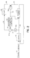
- FIG. 2 is a block diagram of a control system for an actuator, the system incorporating a disturbance estimator and controller according to the invention.
- FIG. 2 illustrates the use of a state space controller.
- a control command 10 is provided which is a source of command signals for the controller.
- the command signal will typically be a position command.
- the position command is coupled to a controller 30.
- the controller 30 also has a feedback signal provided on line 41. In this case, however, the feedback signal is from a model 40, rather than from the plant itself.
- an actuator model 40 which broadly can be characterized as a state model of the system or plant to provide output signals which are estimates of the states of the systems.
- the output 41 taken from the model 40 is intended to be position output, which is coupled back to the controller 30 for comparison with the position command signal 10 to produce a controller output signal 46.
- the controller output signal 46 directly drives the actuator model 40 and by means of a scaling element 30a produces an output signal 31 which is coupled to the plant 55 as a main controller output signal for the plant.
- the main control 30 responds to control commands for module 10 and feedback signals on line 41 to produce a controller output signal on line 46 which controls the position of the plant 55.
- the plant 55 is the actuator, and it is the position of the actuator which is controlled.
- an output of the plant 55 and state output of the actuator model 40 are compared in a comparator 56a to produce an error signal on line 42.
- the position signal on line 56 is typically taken from a transducer (such as a synchro) which measures actuator position, and thus is an actual measure of the controlled output.
- the signal on line 43 is an estimate of the position state taken from the model 40. Differences between those signals can be attributed to disturbances such as friction, and the polarity and magnitude of the signal on line 42 can be sensed to estimate the presence of a disturbance and to control for its effect.
- a disturbance estimator/controller 60 is coupled to the comparator 56a to sense the signal on line 42 and to provide an output signal adapted to compensate for the disturbance.
- the output signal is provided on line 61 and is combined with the controller output on line 31 in summer 61a to produce an output signal 32 which drives the plant 55.
- the output signal and line 61 is not a linear function of the error signal on line 42, nor is it a function which varies linearly with respect to time. Instead, the signal produced by the controller 60 is adapted to compensate for the non-linear characteristics of the disturbances.
- the disturbance output signal 60 is in the form of a two level signal including a step function having a magnitude which is slightly less than the smallest disturbance expected to be encountered, summed with a ramp signal of a magnitude adapted to progress through the disturbance level.
- the disturbance estimator and controller will drive the system in the other direction until the comparator again senses that one has passed the other. The system will continue to alternate conditions in this fashion, and the parameters are such that the movement about a steady state point is very small, and within a tolerable limit cycle.
- the disturbance estimator and controller 60 uses the error signal on line 42 to estimate the disturbance acting on the system, and to generate the force necessary to counteract the disturbance.
- the error signal is determined by comparing the actuator position signal on line 56 from and the model actuator position state on line 43.
- the counterforce generated by the disturbance estimator and controller 60 is added to the compensator signal 31 to generate a control signal 32.
- Control signal 32 is the signal that drives the actuator 55.
- the composite signal 32 which includes both a controller input and a disturbance estimator/controller input drive the plant 55, but only the controller signal 46 is coupled to the model 40.
- the error signal 42 which is derived from the comparator 56a is also connected as an input to the actuator model 40. The specific manner in which this can be accomplished is described below. For the moment, it is adequate to understand that the connection of the error signal to the model assists the model in the following the plant and thus to assist the overall control.
- FIG. 3 illustrates a separate disturbance estimator and disturbance control, and their interrelationship to the remainder of the system.
- a main controller 30 has inputs from a control command module 10 and an actuator model 40 including a system state signal on line 41, typically representative of position.
- the controller 30 produces an output signal 46 which, in this instance is passed through a summer to produce a composite signal on line 32 which drives both the actuator model 40 and the actuator 55.
- a plant feedback signal on line 56 and a model state feedback signal on line 43 are coupled to a comparator 56a to produce an error signal 42.
- the error signal 42 is a measure of the disturbance, and is coupled to the input of the disturbance estimator and controller.
- the disturbance estimator is illustrated as block 60a, and provides an output signal which is coupled to the disturbance controller 60b and also coupled to the actuator model 40.
- the disturbance estimator can consist of simply a comparator and an integrator adapted to mimic friction effects.
- the integrated output signal is then passed to the disturbance controller 60b which produces an output signal coupled to the summer for supplementation of the controller signal 46 so as to overcome the disturbance.
- the composite signal on line 32 in this case is coupled to drive both the model 40 and the actuator 55.
- the disturbance estimator 60a and controller 60b can be combined into a single module. This is particularly the case when the front end dynamics can be approximated by a simple function, such as a constant, in which case the estimator and the controller become the same elements.
- a simple function such as a constant
- the estimator and the controller become the same elements.
- FIG. 3 when the estimator is a more complex element, separate estimator and controller modules can be provided to accomplish the aims of the present invention.
- the actuator 55 can be adequately modeled and represented by a second order state diagram.
- the actuator model 40 includes two serially connected integrators 47 and 45. Feedback signals on lines 44 and 43 represent velocity and position states, respectively. It will thus be appreciated the state model 40 is a rather simple implementation, and only roughly characterizes the state of the system. However, when used as taught the present specification, the model 40 is adequate to provide a sufficient indication of actuator states to be used with the control system and with the disturbance estimator and controller to provide precise feedback control of the actuator.
- the remaining elements illustrated in FIG. 3 are representative of the control elements.
- the summer 48 combines the command signal 10, the position feedback signal from the model on line 43 and, in the present case, a scaled function of the velocity state on line 44.
- the output signal 49 of the summer 48 operates through a gain element 49a to produce an output signal on line 46 which drives both the model 40 and the plant (not illustrated in FIG. 3).
- the gains are determined in part by normalization, and in part by the desired dynamics of the system. For example in FIG. 3, the gain K c1 and K c2 establish the system dynamics.
- FIG. 4 there is shown a simplified implementation of a control system constructed in accordance with the present invention.
- An actuator model 40 is provided which includes integrators 47 and 45 connected to provide a simple state model of the system.
- the input signals through the integrators 47 and 45 are supplemented as described below.
- that signal is supplemented is by a signal on line 53 taken from the error comparator 56a.
- a signal 53 is summed with the signal 46 in a summer 50 to produce an output signal on line 54 which serves as an input for the first integrator 47.
- the signal on line 53 is representative of the error signal on line 42 multiplied by a gain constant K e1 .
- the gain K e1 is explicitly determined by establishing position bandwidth. Indeed, FIG. 6 illustrates both the general constants and the more detailed elements which determine the constants. One of ordinary skill in the art will readily appreciate how one determines the constants based on the bandwidth and factors specified above.
- the input signal 44 is supplemented by a further signal 52 taken from the plant.
- a summer 51 receives signal 44 from the integrator 47 and a further signal on line 52 from a gain element 52a which has the error signal 42 as an input.
- the gain Ke 2 of the element 52a is explicitly determined based on the same variables and methods as the gain K e1 . In this manner, the actuator model 40 is made to more accurately predict the operation and states (e.g., velocity and position) of the actuator 55.
- hysteresis switches 69, 65 for providing current signals which are summed with the controller output to produce a composite drive for the plant. Those switches are used in combination with a disturbance integrator 72 and when utilized as described will tend to produce enough force to overcome friction as quickly as possible but without adversely effecting system performance.
- the output of hysteresis switch 65 serves as a direct input to a summer 75 which provides a composite signal on the output line 32 which is connected to the actuator for driving the actuator.
- the error signal also triggers a second hysteresis switch 69 which drives an integrator 72 to produce a ramp signal which supplements the disturbance control signal on line 66.
- the effect is to produce a composite signal which is summed with the controller signal 31 to overcome the disturbance.
- the hysteresis switches 65, 69 produce output signals which are of a predetermined magnitude and independent of the magnitude of the input error signal 42. Thus, when the error signals switches to a particular polarity the hysteresis switch 65 will produce an output signal of a given magnitude.
- the output signal of the switch 65 is of a constant level and having a magnitude which is just very slightly less than the minimum disturbance known to exist in the system. That step function is supplemented by a ramp produced through the hysteresis switch 69 and disturbance integrator 72. The ramp adds an increasing ramping signal to the constant signal 65 which will quickly push the composite signal through the disturbance.
- the current signal 32 which is coupled to the actuator has three components -- the main controller component on line 31, the minimum valve set magnitude on line 66 and a ramp signal on line 73 which will combine to compensate for the disturbance.
- the disturbance is "estimated” in the sense that the output of the plant and the output of the model are continually monitored by the comparator 56a and when the plant signal passes the signal from the model, the reversal will be determined by the comparator 56a which will reverse the polarity of the error signal 42. That will be immediately sensed by the hysteresis switches 65, 69 which will change their polarity and attempt to drive the actuator in the other direction.
- the degree of "oscillation" about a stable point is sometimes characterized as a "limit cycle". It is a general design and performance goal of feedback control systems to minimize the limit cycle, or at least maintain it within an acceptable zone. What is considered an acceptable zone depends on the system. For example, with the GS10 and GS25 actuators (see below), the seals of the actuator are capable of a certain amount of flex. If the limit cycle of the actuator can be maintained within the flex region of the seals, then the wear and tear on these actuator components will be minimized and the actuator life is extended. Similarly, minimizing actuator movement about the steady state output minimizes wear and tear on other actuator components, e.g. the actuator bearings.
- Maintaining an exceptionally small limit cycle (commonly in the range of 0.02°) will tend to minimize actual error movement occasioned by the disturbance estimator and control system, so as not to adversely wear seals or bearings of the actuator.
- the of friction disturbance is readily accounted for in a highly responsive and accurate result.
- the hysteresis switch 65 produces a constant force component 66
- the integrator 72 produces a force component 73 in the form of a ramp. Force components 66 and 73 are added to the compensator signal 31 at summation point 79 to obtain the control signal 32 which is inputted into the actuator 55 (not shown).
- Control signal 32 will have sufficient current to overcome friction forces and drive the actuator 55 to the desired location. Because of the ramp force component 73, however, the control signal 32 will eventually have too much current and cause the actuator to slightly overshoot the desired steady state location.
- the sign of the error signal 42 changes. When the sign of the error signal 42 changes, the sign of the output of the hysteresis switches 69 and 65 will also change, causing the force components 66 and 73 to be exerted in the opposite direction. The actuator will then be driven in the opposite direction to reach the desired steady state location. Because of the ramp force component 73, however, the actuator will once again slightly overshoot the desired steady state location.
- the overshoot will cause the sign of the error signal 42 to change again, and the actuator will be driven in the opposite direction. Because of the ability of the hysteresis switches 69 and 65 to almost instantaneously change the sign of their output, the actuator will oscillate within an acceptable zone about the desired steady state location (i.e., a limit cycle).
- the disturbance estimator and controller of the invention can maintain this limit cycle at very small values.
- the hysteresis switch 65 provides this immediate counterforce. Depending on whether the sign of the error signal is positive or negative, the hysteresis switch 65 outputs a positive or negative constant current signal 66 to overcome the minimum amount of friction.
- the minimum amount of friction that is always present in the system is determined through experimentation. It must be noted that the outputs of the hysteresis switches 65 and 69 are always constant for any given feedback system.
- the invention also uses the hysteresis switch 69 in conjunction with the disturbance integrator 72 to provide the remaining force component necessary to overcome the friction forces actually present in the system.
- the error signal on line 42 is connected as an input to the hysteresis switch 69. Similar to hysteresis switch 65, hysteresis switch 69 outputs a positive or negative constant current 62, depending on whether the sign of the error signal 42 is positive or negative.
- the output 62 of the hysteresis switch 69 is used as the input of the integrator 72.
- the output of the integrator 72 is a current ramp 73 that, when added to the constant current produced by the hysteresis switch 65, provides sufficient current, i.e., force, to push the actuator as quickly as possible through the friction actually present in the system.
- the output 62 of the hysteresis switch 69 is connected as an input to the integrator 72 to reduce the time necessary for the integrator 72 to produce the amount of current needed to overcome friction.
- the integrator rate must be low enough to avoid oscillations caused by current control mode changes, yet high enough to avoid dropping the small signal bandwidth. In addition, the integrator rate must be less than the value which would cause current driver saturation mode oscillation.
- the integrator 72 can integrate at a constant fast rate even if the magnitude of the error signal is very small which allows maintenance of small signal bandwidth. For example, if the input of the integrator was the error signal, and the error signal was small at the time the actuator needed to overcome a large friction force, it would take the integrator a long time to produce the amount of force needed to push through the friction.
- the integrator 72 can always be integrated quickly, regardless of the magnitude of the error signal.
- the maximum rate of integration In certain applications, e.g., the GS10 or GS25 actuators manufactured by the Woodward Governor Company of Rockford, Illinois, the maximum rate of integration must be kept below a certain limit to avoid adverse effects such as voltage saturation and bandwidth loss. In these actuators, the maximum rate of integration is a function of actuator inductance. The higher the inductance, the lower the maximum rate of integration needs to be. Otherwise, the actuators will suffer from voltage saturation. In other actuators or applications, however, it may be unnecessary to limit the maximum rate of integration.
- the constant force component 66, generated by the hysteresis switch 65, and the ramp force component 73, generated by the integrator 72 and the hysteresis switch 69, are added to the compensator signal 31 at summation point 79 to obtain the control signal 32 which is input to the actuator 55. Because the ramp force component 73 will continue to increase in the desired direction, the control signal 32 will eventually have too much current and cause the actuator to slightly overshoot the desired steady state location.
- the sign of the error signal 42 changes.
- the sign of the output of the hysteresis switches 65 and 69 also change. Consequently, the constant force component 66 and the ramp force 73 will be exerted in the opposite direction as before.
- the magnitude of the ramp force 73 will continue to increase until the actuator has slightly overshot the desired location. At that time, the force components 66 and 73 will change direction again.
- the actuator oscillation about a desired location will continue indefinitely in a limited band sometimes characterized by the term limit cycle. Because of the hysteresis switch ability to almost instantaneously change the direction of their output current, however, the actuator will be able to have a small to negligible limit cycle.
- the ramp force 73 also has the added benefit of compensating for any offsets that may be present in the system. Offsets are errors present in the system due to changes in gain, static state forces, or other causes. The effect of offsets is that the system will need more current than the system model predicts it needs. Therefore, the compensator signal 31 will not be adequate to drive the actuator (if one were to ignore the effects of friction). The ramp force 73 is capable of providing this extra current without adversely affecting system performance. If there is an offset error present in the system, the sign of the error signal 42 will not change until the offset error has been overcome.
- FIG. 6 depicts the invention according to FIG. 5 with two additional linear elements.
- the two additional linear elements allow the estimator and controller to compensate for very large error signals that are not necessarily due to disturbances, e.g., when the actuator is commanded to go from one extreme position to another extreme position.
- FIG. 6 is similar to FIG. 5, and that similar components are located in similar positions.
- the gain blocks in FIG. 6 however include not only the general designator K (with its appropriate subscript), but also the factors which go to make up that gain.
- K general designator
- One skilled in the art will appreciate by the detailed notation of the factors within each of the gain blocks how one goes about determining the particular gains in a particular system. It will be seen, as described in general above, and with the gains thus defined as in FIG. 6, one skilled in the art will be able to configure a control system as described and claimed herein.
- a linear signal component 68 is added to the input of the integrator 72.
- the error signal 42 is multiplied by the gains K e1 and K d to produce a signal 68.
- the signal 68 is added to the output 62 of the hysteresis switch 69 at summation point 70 to obtain the signal 71, which is input to the integrator 72.
- the gain K e1 is the same as was described in connection with FIG. 5.
- Kd is determined by state space or classical techniques that are well known to those with ordinary skill in the art.
- the signal 68 will not contribute significantly to the rate of integration of the integrator 72 because the output of the hysteresis switch 69 will be much larger than the signal 68.
- the signal 68 will help the integrator 72 to integrate faster.
- the second modification from the FIG. 5 implementation is the addition of a third force component on line 67 to the output 73 of the integrator 72.
- the third force component on line 67 is a linear force and is generated by multiplying the error signal 42 by gains K e2 and K d .
- the gains K e2 and K d are the same as described earlier.
- the third force component on line 67 will be small and not very significant when the error signal 42 is small. When the error signal 42 is large, however, the third force component will help to push the actuator to the desired location.
- the constants K e2 and K d are determined such that the sum of the first force component and the third force component is less than the actual disturbance present in the system.
- the third force component 67 is added to the output 73 of the integrator 72 at summation point 75 to generate the signal 77. It is this new signal 77 that is added to the constant force component 66 and the compensator signal 31 at summation point 79 to generate the control signal 32.
- the third force component can be added to the first force component 66, the second force component 73, and the compensator signal 31 directly at summation point 79.
- the hysteresis switches 69 and 65 enable the invention to rapidly overcome friction forces when the error signal is very small (e.g., when the actuator is maintaining a small limit cycle about a desired steady state location), and the linear signals 67 and 68 allow the invention to rapidly reduce a very large error signal (e.g., when the actuator is commanded to move from one extreme position to another).
- FIG. 6 can be considered a basic linear controller on which a non-linear disturbance estimator and integrator is overlaid. While the linear components might be eliminated, if desirable, they illustrate certain benefits of the invention. For example, when a basic controller design originates from linear considerations, it is possible to overlay a non-linear disturbance estimator and controller on those linear elements, and have the two operate together. The elements can then be separated, when desired, and analyzed separately. For example, if trouble shooting is needed, it is possible to disable the non-linear disturbance estimator and to revert to the linear control for debugging purposes. When the control is appropriately debugged, the non-linear disturbance estimator and controller can be again overlaid to achieve the benefits of the invention.
- a state model is provided which can be very simple in construction.
- a basic controller which can be linear if desired, drives both the plant (the actuator) and the state model.
- An output of the state model is compared with a corresponding feedback signal from the plant to generate an error signal.
- the error signal is sensed by the disturbance estimator to actuate a disturbance controller in the presence of a disturbance to impose a non-linear correction on the system to accommodate for the disturbance.
- the control is relatively simple in design yet produces highly desirable control characteristics.
Landscapes
- Engineering & Computer Science (AREA)
- Physics & Mathematics (AREA)
- General Physics & Mathematics (AREA)
- Automation & Control Theory (AREA)
- Human Computer Interaction (AREA)
- Manufacturing & Machinery (AREA)
- Feedback Control In General (AREA)
- Paper (AREA)
Applications Claiming Priority (2)
| Application Number | Priority Date | Filing Date | Title |
|---|---|---|---|
| US3152696P | 1996-11-29 | 1996-11-29 | |
| US31526P | 1996-11-29 |
Publications (3)
| Publication Number | Publication Date |
|---|---|
| EP0845722A2 true EP0845722A2 (fr) | 1998-06-03 |
| EP0845722A3 EP0845722A3 (fr) | 1999-12-01 |
| EP0845722B1 EP0845722B1 (fr) | 2004-10-06 |
Family
ID=21859946
Family Applications (1)
| Application Number | Title | Priority Date | Filing Date |
|---|---|---|---|
| EP97203676A Expired - Lifetime EP0845722B1 (fr) | 1996-11-29 | 1997-11-26 | Méthode et appareil d'estimation et de contrôle de perturbations non linéaires dans un système de commande à réaction |
Country Status (6)
| Country | Link |
|---|---|
| US (1) | US6094602A (fr) |
| EP (1) | EP0845722B1 (fr) |
| JP (1) | JPH10214102A (fr) |
| CN (1) | CN1108545C (fr) |
| AT (1) | ATE278978T1 (fr) |
| DE (1) | DE69731060T2 (fr) |
Cited By (13)
| Publication number | Priority date | Publication date | Assignee | Title |
|---|---|---|---|---|
| WO2001001212A1 (fr) * | 1999-06-23 | 2001-01-04 | Saab Ab | Procede de supervision et de commande d'un dispositif au moyen d'un modele informatique |
| EP1094375A1 (fr) * | 1999-10-18 | 2001-04-25 | Yamatake Corporation | Dispositif et procédé de commande arithmétique |
| WO2002003150A2 (fr) * | 2000-06-30 | 2002-01-10 | The Dow Chemical Company | Commande multi-variable de traitement de matrice |
| EP1220064A2 (fr) * | 2000-12-28 | 2002-07-03 | Seiko Instruments Inc. | Système de commande avec évaluation de perturbation, système de commande d un compresseur de gaz et procédé de conception d'un système de commande avec évaluation de perturbation |
| EP1984858A2 (fr) * | 2006-02-14 | 2008-10-29 | Edsa Micro Corporation | Systemes et procedes pour la surveillance du systeme en temps reel et l'analyse predictive |
| US9092593B2 (en) | 2007-09-25 | 2015-07-28 | Power Analytics Corporation | Systems and methods for intuitive modeling of complex networks in a digital environment |
| US9557723B2 (en) | 2006-07-19 | 2017-01-31 | Power Analytics Corporation | Real-time predictive systems for intelligent energy monitoring and management of electrical power networks |
| CN106873506A (zh) * | 2015-11-30 | 2017-06-20 | 欧姆龙株式会社 | 校正装置、校正装置的控制方法、信息处理程序及记录介质 |
| US10867087B2 (en) | 2006-02-14 | 2020-12-15 | Wavetech Global, Inc. | Systems and methods for real-time DC microgrid power analytics for mission-critical power systems |
| US10962999B2 (en) | 2009-10-01 | 2021-03-30 | Wavetech Global Inc. | Microgrid model based automated real time simulation for market based electric power system optimization |
| CN113050429A (zh) * | 2021-03-29 | 2021-06-29 | 合肥工业大学 | 一种基于非线性建模的电控执行器精确控制方法 |
| CN114253138A (zh) * | 2021-12-16 | 2022-03-29 | 华中科技大学 | 基于动态延时pi模型的纳米定位平台补偿控制方法及系统 |
| WO2023217460A1 (fr) * | 2022-05-09 | 2023-11-16 | Asml Netherlands B.V. | Procédé de commande de système mécatronique, procédé de commande d'appareil lithographique et appareil lithographique |
Families Citing this family (44)
| Publication number | Priority date | Publication date | Assignee | Title |
|---|---|---|---|---|
| DE29903016U1 (de) * | 1999-02-19 | 2000-05-11 | Siemens AG, 80333 München | Schrittregler |
| KR100467490B1 (ko) * | 2000-07-31 | 2005-01-24 | 주식회사 대우일렉트로닉스 | 디스크 드라이브 포커싱 제어 방법 |
| GB0113627D0 (en) | 2001-06-05 | 2001-07-25 | Univ Stirling | Controller and method of controlling an apparatus |
| CN100452229C (zh) * | 2002-09-26 | 2009-01-14 | 宇田控股有限公司 | 一种光学读取头的读取速度控制装置及其方法 |
| US8463441B2 (en) | 2002-12-09 | 2013-06-11 | Hudson Technologies, Inc. | Method and apparatus for optimizing refrigeration systems |
| DE10300543B4 (de) * | 2003-01-09 | 2005-01-13 | Siemens Ag | Verfahren zur Streckenidentifikation einer Regelstrecke |
| SE0301531L (sv) | 2003-05-22 | 2004-11-23 | Abb Ab | A Control method for a robot |
| JP4015589B2 (ja) * | 2003-06-02 | 2007-11-28 | 本田技研工業株式会社 | プラントの制御装置 |
| JP4598474B2 (ja) * | 2004-10-07 | 2010-12-15 | 本田技研工業株式会社 | プラントの制御装置 |
| WO2007001252A1 (fr) * | 2005-06-13 | 2007-01-04 | Carnegie Mellon University | Appareils, systemes et procedes a commande adaptative |
| US7797082B2 (en) * | 2005-10-13 | 2010-09-14 | Honeywell International Inc. | Apparatus and method for stiction compensation in a process control system |
| US7620460B2 (en) * | 2005-10-25 | 2009-11-17 | Fisher-Rosemount Systems, Inc. | Process control with unreliable communications |
| US8719327B2 (en) * | 2005-10-25 | 2014-05-06 | Fisher-Rosemount Systems, Inc. | Wireless communication of process measurements |
| US7587252B2 (en) * | 2005-10-25 | 2009-09-08 | Fisher-Rosemount Systems, Inc. | Non-periodic control communications in wireless and other process control systems |
| US7345373B2 (en) * | 2005-11-29 | 2008-03-18 | General Electric Company | System and method for utility and wind turbine control |
| JP4518028B2 (ja) * | 2006-02-13 | 2010-08-04 | Smc株式会社 | 位置決め制御システム及びフィルタ |
| US7894473B2 (en) * | 2006-04-12 | 2011-02-22 | Honeywell International Inc. | System and method for monitoring valve status and performance in a process control system |
| DE502006003019D1 (de) * | 2006-08-31 | 2009-04-16 | Integrated Dynamics Eng Gmbh | Aktives Schwingungsisolationssystem mittels hysteresefreier pneumatischer Lagerung |
| US7787978B2 (en) * | 2006-10-03 | 2010-08-31 | Honeywell International Inc. | Apparatus and method for controller performance monitoring in a process control system |
| US8571095B2 (en) | 2006-12-19 | 2013-10-29 | Nec Corporation | Equalization filter and distortion compensating method |
| US7933701B2 (en) * | 2006-12-28 | 2011-04-26 | Caterpillar Inc. | Closed-loop motion-control system using error to modify gain |
| CN101339406B (zh) * | 2007-07-04 | 2011-05-11 | 中国科学院自动化研究所 | 一种自适应控制器及方法 |
| US8067917B2 (en) * | 2008-04-08 | 2011-11-29 | Liebert Corporation | Hysteresis mitigation and control method |
| DE102009004569B4 (de) * | 2009-01-14 | 2014-02-13 | Abb Technology Ag | Verfahren und elektronische Einrichtung zur Kompensation der Hysterese von pneumatisch angetriebenen Armaturen |
| DE102009004571A1 (de) | 2009-01-14 | 2010-07-22 | Abb Technology Ag | Verfahren und elektronische Einrichtung zum Prüfen von Ansteuerparametern eines elektro-pneumatischen Ventils bei einem pneumatischen Stellantrieb |
| DE102009004570B4 (de) * | 2009-01-14 | 2019-11-14 | Abb Schweiz Ag | Verfahren und elektronische Einrichtung zum Finden des Öffnungspunktes bei einem geregelten elektro-pneumatischen Ventil eines pneumatischen Stellantriebs |
| DE102009004572B4 (de) * | 2009-01-14 | 2010-08-19 | Abb Technology Ag | Verfahren und elektronische Einrichtung zur Kompensation des Driftverhaltens bei einem pneumatischen Stellglied während des Betriebs |
| US8587320B2 (en) | 2010-11-09 | 2013-11-19 | Honeywell International Inc. | System and method for testing a secondary servo control circuit in a redundant control configuration |
| JP5780783B2 (ja) * | 2011-03-04 | 2015-09-16 | 富士機械製造株式会社 | 干渉力補償制御装置 |
| WO2013007867A1 (fr) * | 2011-07-11 | 2013-01-17 | Metso Automation Oy | Commande sans fil pour automatisation de procédé |
| EP2573631B1 (fr) * | 2011-09-23 | 2015-10-21 | Honeywell spol s.r.o. | Contrôleur qui estime des variables manipulées retardées |
| US9298176B2 (en) | 2012-01-17 | 2016-03-29 | Fisher-Rosemount Systems, Inc. | Compensating for setpoint changes in a non-periodically updated controller |
| US10423127B2 (en) | 2012-01-17 | 2019-09-24 | Fisher-Rosemount Systems, Inc. | Velocity based control in a non-periodically updated controller |
| US11199824B2 (en) | 2012-01-17 | 2021-12-14 | Fisher-Rosemount Systems, Inc. | Reducing controller updates in a control loop |
| DE102012013384A1 (de) * | 2012-06-19 | 2013-12-19 | Robert Bosch Gmbh | Regelvorrichtung und regelverfahrenzur regelung eines von einer maschinedurchgeführten verfahrens |
| US9625902B2 (en) * | 2014-03-31 | 2017-04-18 | Bose Corporation | Method and system for detecting integrity of a control loop of a physical system |
| JP6238869B2 (ja) * | 2014-10-28 | 2017-11-29 | アズビル株式会社 | 接触制御装置 |
| US10381031B2 (en) | 2015-03-31 | 2019-08-13 | Seagate Technology Llc | Adaptive disturbance rejection using dead zone filter |
| JP6664807B2 (ja) * | 2015-08-20 | 2020-03-13 | 国立大学法人東京農工大学 | 制御装置、制御方法、及び制御プログラム |
| JP6441205B2 (ja) * | 2015-11-20 | 2018-12-19 | 東京計装株式会社 | サーボバランス式液面計の制御方法 |
| KR102353783B1 (ko) * | 2016-06-29 | 2022-01-19 | 일리노이즈 툴 워크스 인코포레이티드 | 가변 시스템 파라미터들의 실시간 보상을 갖는 시험 시스템 |
| CN108107751A (zh) * | 2017-12-29 | 2018-06-01 | 哈尔滨安天科技股份有限公司 | 一种工业仿真控制系统的仿真反馈方法及系统 |
| CN110879618B (zh) * | 2019-12-02 | 2022-07-29 | 中国科学院光电技术研究所 | 一种基于加速度和位置扰动信息的多扰动观测器三闭环稳定跟踪方法 |
| KR20230015100A (ko) * | 2021-07-22 | 2023-01-31 | 재단법인대구경북과학기술원 | 입출력 데이터 기반 제어 시스템 외란 추정 방법 및 장치 |
Citations (3)
| Publication number | Priority date | Publication date | Assignee | Title |
|---|---|---|---|---|
| US5115418A (en) * | 1989-09-25 | 1992-05-19 | Seiko Instruments Inc. | Servo control apparatus |
| US5274314A (en) * | 1993-02-12 | 1993-12-28 | Texas Instruments Incorporated | Adaptive friction compensator |
| WO1995027930A1 (fr) * | 1994-04-08 | 1995-10-19 | Siemens Aktiengesellschaft | Systeme permettant de compenser la non-linearite d'arbres de machines |
Family Cites Families (5)
| Publication number | Priority date | Publication date | Assignee | Title |
|---|---|---|---|---|
| US4038531A (en) * | 1976-05-18 | 1977-07-26 | Weyerhaeuser Company | Process control apparatus for controlling a particleboard manufacturing system |
| DE3572740D1 (en) * | 1984-04-13 | 1989-10-05 | Toshiba Kk | Process control apparatus |
| US5374884A (en) * | 1992-11-18 | 1994-12-20 | University Of Michigan, The Board Of Regents Acting . . . | Model-based position-repeatable disturbance compensation |
| DE69315318D1 (de) * | 1992-12-07 | 1998-01-02 | Koninkl Philips Electronics Nv | Steuerungseinrichtung |
| FR2702035B1 (fr) * | 1993-02-24 | 1995-05-12 | Gec Alsthom Transport Sa | Dispositif de régulation de climatisation d'un local. |
-
1997
- 1997-11-26 US US08/980,031 patent/US6094602A/en not_active Expired - Lifetime
- 1997-11-26 AT AT97203676T patent/ATE278978T1/de not_active IP Right Cessation
- 1997-11-26 EP EP97203676A patent/EP0845722B1/fr not_active Expired - Lifetime
- 1997-11-26 DE DE69731060T patent/DE69731060T2/de not_active Expired - Lifetime
- 1997-11-29 CN CN97125234A patent/CN1108545C/zh not_active Expired - Fee Related
- 1997-12-01 JP JP9364714A patent/JPH10214102A/ja active Pending
Patent Citations (3)
| Publication number | Priority date | Publication date | Assignee | Title |
|---|---|---|---|---|
| US5115418A (en) * | 1989-09-25 | 1992-05-19 | Seiko Instruments Inc. | Servo control apparatus |
| US5274314A (en) * | 1993-02-12 | 1993-12-28 | Texas Instruments Incorporated | Adaptive friction compensator |
| WO1995027930A1 (fr) * | 1994-04-08 | 1995-10-19 | Siemens Aktiengesellschaft | Systeme permettant de compenser la non-linearite d'arbres de machines |
Non-Patent Citations (1)
| Title |
|---|
| SCHAFER U ET AL: "MODEL REFERENCE POSITION CONTROL OF AN ELASTIC TWO-MASS SYSTEM WITH COMPENSATION OF COULOMB FRICTION" PROCEEDINGS OF THE AMERICAN CONTROL CONFERENCE, SAN FRANCISCO, JUNE 2 - 4, 1993, vol. 2, 2 June 1993 (1993-06-02), pages 1937-1941, XP000411154 INSTITUTE OF ELECTRICAL AND ELECTRONICS ENGINEERS * |
Cited By (23)
| Publication number | Priority date | Publication date | Assignee | Title |
|---|---|---|---|---|
| WO2001001212A1 (fr) * | 1999-06-23 | 2001-01-04 | Saab Ab | Procede de supervision et de commande d'un dispositif au moyen d'un modele informatique |
| EP1094375A1 (fr) * | 1999-10-18 | 2001-04-25 | Yamatake Corporation | Dispositif et procédé de commande arithmétique |
| US6754542B1 (en) | 1999-10-18 | 2004-06-22 | Yamatake Corporation | Control arithmetic apparatus and method |
| WO2002003150A2 (fr) * | 2000-06-30 | 2002-01-10 | The Dow Chemical Company | Commande multi-variable de traitement de matrice |
| WO2002003150A3 (fr) * | 2000-06-30 | 2002-05-02 | Dow Chemical Co | Commande multi-variable de traitement de matrice |
| EP1220064A2 (fr) * | 2000-12-28 | 2002-07-03 | Seiko Instruments Inc. | Système de commande avec évaluation de perturbation, système de commande d un compresseur de gaz et procédé de conception d'un système de commande avec évaluation de perturbation |
| EP1220064A3 (fr) * | 2000-12-28 | 2003-05-21 | Seiko Instruments Inc. | Système de commande avec évaluation de perturbation, système de commande d un compresseur de gaz et procédé de conception d'un système de commande avec évaluation de perturbation |
| US7142930B2 (en) | 2000-12-28 | 2006-11-28 | Calsonic Compressor Manufacturing Inc. | Disturbance estimated type control system, gas compressor control system and method of designing a disturbance estimated type control system |
| US8155908B2 (en) | 2006-02-14 | 2012-04-10 | Power Analytics Corporation | Systems and methods for real-time system monitoring and predictive analysis |
| EP1984858A4 (fr) * | 2006-02-14 | 2011-06-15 | Edsa Micro Corp | Systemes et procedes pour la surveillance du systeme en temps reel et l'analyse predictive |
| EP1984858A2 (fr) * | 2006-02-14 | 2008-10-29 | Edsa Micro Corporation | Systemes et procedes pour la surveillance du systeme en temps reel et l'analyse predictive |
| US10867087B2 (en) | 2006-02-14 | 2020-12-15 | Wavetech Global, Inc. | Systems and methods for real-time DC microgrid power analytics for mission-critical power systems |
| US9557723B2 (en) | 2006-07-19 | 2017-01-31 | Power Analytics Corporation | Real-time predictive systems for intelligent energy monitoring and management of electrical power networks |
| US9092593B2 (en) | 2007-09-25 | 2015-07-28 | Power Analytics Corporation | Systems and methods for intuitive modeling of complex networks in a digital environment |
| US10962999B2 (en) | 2009-10-01 | 2021-03-30 | Wavetech Global Inc. | Microgrid model based automated real time simulation for market based electric power system optimization |
| CN106873506B (zh) * | 2015-11-30 | 2019-12-06 | 欧姆龙株式会社 | 校正装置、校正装置的控制方法、信息处理程序及记录介质 |
| US10241490B2 (en) | 2015-11-30 | 2019-03-26 | Omron Corporation | Correction device, correction device controlling method, information processing program, and recording medium |
| CN106873506A (zh) * | 2015-11-30 | 2017-06-20 | 欧姆龙株式会社 | 校正装置、校正装置的控制方法、信息处理程序及记录介质 |
| CN113050429A (zh) * | 2021-03-29 | 2021-06-29 | 合肥工业大学 | 一种基于非线性建模的电控执行器精确控制方法 |
| CN113050429B (zh) * | 2021-03-29 | 2022-03-22 | 合肥工业大学 | 一种基于非线性建模的电控执行器精确控制方法 |
| CN114253138A (zh) * | 2021-12-16 | 2022-03-29 | 华中科技大学 | 基于动态延时pi模型的纳米定位平台补偿控制方法及系统 |
| CN114253138B (zh) * | 2021-12-16 | 2024-04-05 | 华中科技大学 | 基于动态延时pi模型的纳米定位平台补偿控制方法及系统 |
| WO2023217460A1 (fr) * | 2022-05-09 | 2023-11-16 | Asml Netherlands B.V. | Procédé de commande de système mécatronique, procédé de commande d'appareil lithographique et appareil lithographique |
Also Published As
| Publication number | Publication date |
|---|---|
| EP0845722B1 (fr) | 2004-10-06 |
| DE69731060T2 (de) | 2005-11-17 |
| CN1108545C (zh) | 2003-05-14 |
| JPH10214102A (ja) | 1998-08-11 |
| ATE278978T1 (de) | 2004-10-15 |
| CN1195796A (zh) | 1998-10-14 |
| EP0845722A3 (fr) | 1999-12-01 |
| DE69731060D1 (de) | 2004-11-11 |
| US6094602A (en) | 2000-07-25 |
Similar Documents
| Publication | Publication Date | Title |
|---|---|---|
| EP0845722B1 (fr) | Méthode et appareil d'estimation et de contrôle de perturbations non linéaires dans un système de commande à réaction | |
| CN101573525B (zh) | Egr阀控制装置 | |
| DeCastro | Rate-based model predictive control of turbofan engine clearance | |
| JPS6280197A (ja) | プロペラ シンクロフエ−ザ | |
| US6523522B1 (en) | Method and apparatus for operating a throttle plate motor driving a throttle plate having opposing return springs | |
| JP3362053B2 (ja) | 自動車のアクチュエータを制御する装置 | |
| CN113625547A (zh) | 一种控制器的主阀位置控制方法 | |
| JP3606142B2 (ja) | 無段変速機の変速比制御システム | |
| CN116520684A (zh) | 基于自抗扰控制和Youla参数化的控制器优化方法 | |
| US20130018502A1 (en) | Method for controlling the movement of a component or machine element inhibited by friction | |
| KR100284092B1 (ko) | 인공신경망을 이용한 유압시스템 및 그 제어방법 | |
| US20220065270A1 (en) | Double corrector for asymmetrical mechanism compensation | |
| JP2001050418A (ja) | バルブポジショナ | |
| JP3765371B2 (ja) | バルブポジショナ | |
| JP3039267B2 (ja) | バルブポジショナ | |
| JP4247699B2 (ja) | 非線形制御対象のフィードバック制御方法 | |
| US20240117779A1 (en) | Closed-loop control device for closed-loop control of a power assembly including an internal combustion engine and a generator having an operative drive connection to the internal combustion engine, closed-loop control arrangement having such a closed-loop control device, power assembly and method for closed-loop control of a power assembly | |
| JP2002341904A (ja) | プラントの制御装置 | |
| JP2010077821A (ja) | 電子ガバナの制御方法及びその制御装置 | |
| JP6564732B2 (ja) | 変速機制御装置 | |
| CN115773186A (zh) | 一种船用大功率柴油机的调速控制方法及系统 | |
| CN117193085A (zh) | 一种用于具有惯性延迟和纯延迟系统的补偿预估控制系统 | |
| RU2172419C1 (ru) | Способ управления многомерным объектом | |
| RU2172857C1 (ru) | Система автоматического регулирования газотурбинного двигателя | |
| KR20220058711A (ko) | 유량 제어용 서보 밸브의 제어 장치 및 그 제어 방법 |
Legal Events
| Date | Code | Title | Description |
|---|---|---|---|
| PUAI | Public reference made under article 153(3) epc to a published international application that has entered the european phase |
Free format text: ORIGINAL CODE: 0009012 |
|
| AK | Designated contracting states |
Kind code of ref document: A2 Designated state(s): AT BE CH DE DK ES FI FR GB GR IE IT LI LU MC NL PT SE |
|
| AX | Request for extension of the european patent |
Free format text: AL;LT;LV;MK;RO;SI |
|
| PUAL | Search report despatched |
Free format text: ORIGINAL CODE: 0009013 |
|
| AK | Designated contracting states |
Kind code of ref document: A3 Designated state(s): AT BE CH DE DK ES FI FR GB GR IE IT LI LU MC NL PT SE |
|
| AX | Request for extension of the european patent |
Free format text: AL;LT;LV;MK;RO;SI |
|
| AKX | Designation fees paid | ||
| REG | Reference to a national code |
Ref country code: DE Ref legal event code: 8566 |
|
| RAX | Requested extension states of the european patent have changed |
Free format text: AL PAYMENT 20000911;LT PAYMENT 20000911;LV PAYMENT 20000911;MK PAYMENT 20000911;RO PAYMENT 20000911;SI PAYMENT 20000911 |
|
| RBV | Designated contracting states (corrected) |
Designated state(s): AT BE CH DE DK ES FI FR GB GR IE IT LI LU MC NL PT SE |
|
| 17P | Request for examination filed |
Effective date: 20000602 |
|
| 17Q | First examination report despatched |
Effective date: 20020221 |
|
| GRAP | Despatch of communication of intention to grant a patent |
Free format text: ORIGINAL CODE: EPIDOSNIGR1 |
|
| GRAS | Grant fee paid |
Free format text: ORIGINAL CODE: EPIDOSNIGR3 |
|
| GRAA | (expected) grant |
Free format text: ORIGINAL CODE: 0009210 |
|
| AK | Designated contracting states |
Kind code of ref document: B1 Designated state(s): AT BE CH DE DK ES FI FR GB GR IE IT LI LU MC NL PT SE |
|
| AX | Request for extension of the european patent |
Extension state: AL LT LV MK RO SI |
|
| PG25 | Lapsed in a contracting state [announced via postgrant information from national office to epo] |
Ref country code: SE Free format text: LAPSE BECAUSE OF FAILURE TO SUBMIT A TRANSLATION OF THE DESCRIPTION OR TO PAY THE FEE WITHIN THE PRESCRIBED TIME-LIMIT Effective date: 20041006 Ref country code: NL Free format text: LAPSE BECAUSE OF FAILURE TO SUBMIT A TRANSLATION OF THE DESCRIPTION OR TO PAY THE FEE WITHIN THE PRESCRIBED TIME-LIMIT Effective date: 20041006 Ref country code: LI Free format text: LAPSE BECAUSE OF FAILURE TO SUBMIT A TRANSLATION OF THE DESCRIPTION OR TO PAY THE FEE WITHIN THE PRESCRIBED TIME-LIMIT Effective date: 20041006 Ref country code: IT Free format text: LAPSE BECAUSE OF FAILURE TO SUBMIT A TRANSLATION OF THE DESCRIPTION OR TO PAY THE FEE WITHIN THE PRE;WARNING: LAPSES OF ITALIAN PATENTS WITH EFFECTIVE DATE BEFORE 2007 MAY HAVE OCCURRED AT ANY TIME BEFORE 2007. THE CORRECT EFFECTIVE DATE MAY BE DIFFERENT FROM THE ONE RECORDED.SCRIBED TIME-LIMIT Effective date: 20041006 Ref country code: FR Free format text: LAPSE BECAUSE OF NON-PAYMENT OF DUE FEES Effective date: 20041006 Ref country code: FI Free format text: LAPSE BECAUSE OF FAILURE TO SUBMIT A TRANSLATION OF THE DESCRIPTION OR TO PAY THE FEE WITHIN THE PRESCRIBED TIME-LIMIT Effective date: 20041006 Ref country code: CH Free format text: LAPSE BECAUSE OF FAILURE TO SUBMIT A TRANSLATION OF THE DESCRIPTION OR TO PAY THE FEE WITHIN THE PRESCRIBED TIME-LIMIT Effective date: 20041006 Ref country code: BE Free format text: LAPSE BECAUSE OF FAILURE TO SUBMIT A TRANSLATION OF THE DESCRIPTION OR TO PAY THE FEE WITHIN THE PRESCRIBED TIME-LIMIT Effective date: 20041006 Ref country code: AT Free format text: LAPSE BECAUSE OF FAILURE TO SUBMIT A TRANSLATION OF THE DESCRIPTION OR TO PAY THE FEE WITHIN THE PRESCRIBED TIME-LIMIT Effective date: 20041006 |
|
| REG | Reference to a national code |
Ref country code: GB Ref legal event code: FG4D |
|
| REG | Reference to a national code |
Ref country code: CH Ref legal event code: EP |
|
| REG | Reference to a national code |
Ref country code: IE Ref legal event code: FG4D |
|
| REF | Corresponds to: |
Ref document number: 69731060 Country of ref document: DE Date of ref document: 20041111 Kind code of ref document: P |
|
| PG25 | Lapsed in a contracting state [announced via postgrant information from national office to epo] |
Ref country code: LU Free format text: LAPSE BECAUSE OF NON-PAYMENT OF DUE FEES Effective date: 20041126 Ref country code: IE Free format text: LAPSE BECAUSE OF NON-PAYMENT OF DUE FEES Effective date: 20041126 |
|
| PG25 | Lapsed in a contracting state [announced via postgrant information from national office to epo] |
Ref country code: MC Free format text: LAPSE BECAUSE OF NON-PAYMENT OF DUE FEES Effective date: 20041130 |
|
| PG25 | Lapsed in a contracting state [announced via postgrant information from national office to epo] |
Ref country code: GR Free format text: LAPSE BECAUSE OF FAILURE TO SUBMIT A TRANSLATION OF THE DESCRIPTION OR TO PAY THE FEE WITHIN THE PRESCRIBED TIME-LIMIT Effective date: 20050106 Ref country code: DK Free format text: LAPSE BECAUSE OF FAILURE TO SUBMIT A TRANSLATION OF THE DESCRIPTION OR TO PAY THE FEE WITHIN THE PRESCRIBED TIME-LIMIT Effective date: 20050106 |
|
| PG25 | Lapsed in a contracting state [announced via postgrant information from national office to epo] |
Ref country code: ES Free format text: LAPSE BECAUSE OF FAILURE TO SUBMIT A TRANSLATION OF THE DESCRIPTION OR TO PAY THE FEE WITHIN THE PRESCRIBED TIME-LIMIT Effective date: 20050117 |
|
| LTIE | Lt: invalidation of european patent or patent extension |
Effective date: 20041006 |
|
| NLV1 | Nl: lapsed or annulled due to failure to fulfill the requirements of art. 29p and 29m of the patents act | ||
| REG | Reference to a national code |
Ref country code: CH Ref legal event code: PL |
|
| PLBE | No opposition filed within time limit |
Free format text: ORIGINAL CODE: 0009261 |
|
| STAA | Information on the status of an ep patent application or granted ep patent |
Free format text: STATUS: NO OPPOSITION FILED WITHIN TIME LIMIT |
|
| REG | Reference to a national code |
Ref country code: IE Ref legal event code: MM4A |
|
| 26N | No opposition filed |
Effective date: 20050707 |
|
| EN | Fr: translation not filed | ||
| PG25 | Lapsed in a contracting state [announced via postgrant information from national office to epo] |
Ref country code: PT Free format text: LAPSE BECAUSE OF NON-PAYMENT OF DUE FEES Effective date: 20050306 |
|
| PGFP | Annual fee paid to national office [announced via postgrant information from national office to epo] |
Ref country code: GB Payment date: 20151127 Year of fee payment: 19 Ref country code: DE Payment date: 20151127 Year of fee payment: 19 |
|
| REG | Reference to a national code |
Ref country code: DE Ref legal event code: R119 Ref document number: 69731060 Country of ref document: DE |
|
| GBPC | Gb: european patent ceased through non-payment of renewal fee |
Effective date: 20161126 |
|
| PG25 | Lapsed in a contracting state [announced via postgrant information from national office to epo] |
Ref country code: DE Free format text: LAPSE BECAUSE OF NON-PAYMENT OF DUE FEES Effective date: 20170601 Ref country code: GB Free format text: LAPSE BECAUSE OF NON-PAYMENT OF DUE FEES Effective date: 20161126 |