EP0843229A2 - Automatische Wartungsanforderung über das weltweite Netz - Google Patents
Automatische Wartungsanforderung über das weltweite Netz Download PDFInfo
- Publication number
- EP0843229A2 EP0843229A2 EP97307545A EP97307545A EP0843229A2 EP 0843229 A2 EP0843229 A2 EP 0843229A2 EP 97307545 A EP97307545 A EP 97307545A EP 97307545 A EP97307545 A EP 97307545A EP 0843229 A2 EP0843229 A2 EP 0843229A2
- Authority
- EP
- European Patent Office
- Prior art keywords
- peripheral device
- network
- packet
- process steps
- status information
- Prior art date
- Legal status (The legal status is an assumption and is not a legal conclusion. Google has not performed a legal analysis and makes no representation as to the accuracy of the status listed.)
- Ceased
Links
Images


Classifications
-
- G—PHYSICS
- G06—COMPUTING; CALCULATING OR COUNTING
- G06F—ELECTRIC DIGITAL DATA PROCESSING
- G06F11/00—Error detection; Error correction; Monitoring
- G06F11/07—Responding to the occurrence of a fault, e.g. fault tolerance
- G06F11/0703—Error or fault processing not based on redundancy, i.e. by taking additional measures to deal with the error or fault not making use of redundancy in operation, in hardware, or in data representation
- G06F11/0706—Error or fault processing not based on redundancy, i.e. by taking additional measures to deal with the error or fault not making use of redundancy in operation, in hardware, or in data representation the processing taking place on a specific hardware platform or in a specific software environment
- G06F11/0733—Error or fault processing not based on redundancy, i.e. by taking additional measures to deal with the error or fault not making use of redundancy in operation, in hardware, or in data representation the processing taking place on a specific hardware platform or in a specific software environment in a data processing system embedded in an image processing device, e.g. printer, facsimile, scanner
-
- G—PHYSICS
- G03—PHOTOGRAPHY; CINEMATOGRAPHY; ANALOGOUS TECHNIQUES USING WAVES OTHER THAN OPTICAL WAVES; ELECTROGRAPHY; HOLOGRAPHY
- G03G—ELECTROGRAPHY; ELECTROPHOTOGRAPHY; MAGNETOGRAPHY
- G03G15/00—Apparatus for electrographic processes using a charge pattern
- G03G15/50—Machine control of apparatus for electrographic processes using a charge pattern, e.g. regulating differents parts of the machine, multimode copiers, microprocessor control
- G03G15/5075—Remote control machines, e.g. by a host
- G03G15/5079—Remote control machines, e.g. by a host for maintenance
-
- G—PHYSICS
- G06—COMPUTING; CALCULATING OR COUNTING
- G06F—ELECTRIC DIGITAL DATA PROCESSING
- G06F11/00—Error detection; Error correction; Monitoring
- G06F11/07—Responding to the occurrence of a fault, e.g. fault tolerance
- G06F11/0703—Error or fault processing not based on redundancy, i.e. by taking additional measures to deal with the error or fault not making use of redundancy in operation, in hardware, or in data representation
- G06F11/0706—Error or fault processing not based on redundancy, i.e. by taking additional measures to deal with the error or fault not making use of redundancy in operation, in hardware, or in data representation the processing taking place on a specific hardware platform or in a specific software environment
- G06F11/0748—Error or fault processing not based on redundancy, i.e. by taking additional measures to deal with the error or fault not making use of redundancy in operation, in hardware, or in data representation the processing taking place on a specific hardware platform or in a specific software environment in a remote unit communicating with a single-box computer node experiencing an error/fault
-
- G—PHYSICS
- G06—COMPUTING; CALCULATING OR COUNTING
- G06F—ELECTRIC DIGITAL DATA PROCESSING
- G06F11/00—Error detection; Error correction; Monitoring
- G06F11/30—Monitoring
- G06F11/32—Monitoring with visual or acoustical indication of the functioning of the machine
- G06F11/324—Display of status information
- G06F11/328—Computer systems status display
-
- G—PHYSICS
- G03—PHOTOGRAPHY; CINEMATOGRAPHY; ANALOGOUS TECHNIQUES USING WAVES OTHER THAN OPTICAL WAVES; ELECTROGRAPHY; HOLOGRAPHY
- G03G—ELECTROGRAPHY; ELECTROPHOTOGRAPHY; MAGNETOGRAPHY
- G03G15/00—Apparatus for electrographic processes using a charge pattern
- G03G15/55—Self-diagnostics; Malfunction or lifetime display
-
- G—PHYSICS
- G03—PHOTOGRAPHY; CINEMATOGRAPHY; ANALOGOUS TECHNIQUES USING WAVES OTHER THAN OPTICAL WAVES; ELECTROGRAPHY; HOLOGRAPHY
- G03G—ELECTROGRAPHY; ELECTROPHOTOGRAPHY; MAGNETOGRAPHY
- G03G2215/00—Apparatus for electrophotographic processes
- G03G2215/00025—Machine control, e.g. regulating different parts of the machine
- G03G2215/00109—Remote control of apparatus, e.g. by a host
- G03G2215/00113—Plurality of apparatus configured in groups each with its own host
-
- G—PHYSICS
- G06—COMPUTING; CALCULATING OR COUNTING
- G06F—ELECTRIC DIGITAL DATA PROCESSING
- G06F11/00—Error detection; Error correction; Monitoring
- G06F11/22—Detection or location of defective computer hardware by testing during standby operation or during idle time, e.g. start-up testing
- G06F11/2294—Detection or location of defective computer hardware by testing during standby operation or during idle time, e.g. start-up testing by remote test
Definitions
- the present invention concerns techniques by which a network peripheral device may send an automatic service request over the world wide web or other network and means for implementing such techniques.
- a peripheral device such as a network copier required manufacturer's servicing
- the user was required to first notice the condition necessitating service, such as inoperability or an error message displayed by the peripheral device, by physically inspecting the device. Then, the user had to notify the manufacturer's technical support or servicing department, for example by placing a telephone call or faxing a service request form. This latter step often involved locating and providing various types of information to the manufacturer's technical support department, and presented a significant potential for error in communicating the information accurately.
- a peripheral device requiring service would initiate a modem connection to the service organization and then would communicate servicing request information via the modem connection.
- a method has several drawbacks.
- Second, using the modem connection technique generally only allows a service organization, such as technical support, to receive service requests over periods during which it maintains a server connected to a modem at a preestablished telephone number.
- a network peripheral device means a peripheral device together with a network board for communicating over a network.
- the service request can be a request for technical maintenance and service or might be a request, for example, to a sales organization ordering a part. Additionally, the service request might be triggered completely internally to the peripheral device making the request or might be triggered based on some external input or instruction.
- the present invention simultaneously automates the service request procedure, unlike modem connection methods, the present invention permits the service organization to receive data while connected to the internet, regardless of where its server is located geographically. As a result, the present invention permits the service organization to implement flexible methods of business operation which presently might not be easily obtainable with a modem connection method.
- the invention communicates status information to a remote service organization from a network peripheral device connected to a network router.
- a condition of the network peripheral device is detected.
- status information is automatically obtained, the status information corresponding to the detected condition.
- a packet is automatically transmitted to the remote service organization via the network, the packet containing the status information.
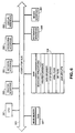
- Figure 1 is a diagram of a network architecture of an embodiment of the present invention.
- Figure 2 is a diagram showing the physical layout of components on a network board of an embodiment of the present invention.
- Figure 3 is a functional block diagram of the network board.
- Figure 4 is a perspective view showing the outward appearance of a workstation of an embodiment of the present invention.
- Figure 5 is a block diagram of a user's workstation.
- Figure 6 is a block diagram of a technical support operator's workstation.
- Figure 7 is a copier home page as displayed by an Internet browser.
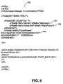
- Figure 8 is an HTML file corresponding to the copier home page of Figure 7.
- Figure 9 is an HTML file corresponding to a Tab Frame of the copier home page of Figure 7.
- Figure 10 is an "Administration" web page as displayed by a browser.
- Figure 11 is an HTML file corresponding to the "Administration" web page of Figure 10.
- Figure 12 is a Technical Support server home page as displayed by a browser.
- Figure 13 is a flowchart for describing process steps to create an SNMP client in a workstation and to reboot a copier via the SNMP client.
- Figure 14 is a flowchart for describing process steps to send copier information to a technical support organization.
- Figure 15 is a flowchart for describing process steps to send copier information to a technical support organization.
- Figure 16 depicts a Web page for providing servicing information generated by a network copier in response to a service organization request.
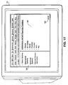
- Figure 17 depicts a Web page showing maintenance and diagnostic functions available to be executed by a network copier.
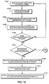
- Figure 18 is a flowchart for describing a method for performing remote maintenance and servicing of a network copier over the internet.
- Figure 19 depicts a service request page automatically generated by a network copier in response to a detected condition.
- Figure 20 is a flowchart for describing a method by which a network peripheral device may send an automatic service request over an IP-network.
- Figure 1 is a diagram of a network architecture which can be used to implement an embodiment of the present invention. Included in Figure 1 is Network Interface Board (NIB) 14, an example of which is described in U.S. Patent Application No. 08/409,034, filed March 23, 1995, entitled "Network Interface Board For Digital Copier".
- the NIB 14 is coupled to a copier 11 having an open architecture through a Multi-Device Controller (MDC) 12.
- MDC Multi-Device Controller
- the copier 11 is a Canon GP-55 or other copier capable of establishing a robust interface with NIB 14.
- the NIB 14 is also coupled to a local area network (LAN) 15 through a LAN interface, for example, an Ethernet interface 10Base-2 with a Coax connector or 10Base-T with an RJ-45 connector.
- LAN local area network
- the present invention may utilize a LAN conforming to a Token-ring architecture.
- Plural workstations such as workstations 9 and 16, are also connected to the LAN 15, and under control of the network operating system these workstations are able to communicate with the NIB 14.
- One of the workstations, such as workstation 9, may be designated for use as the network administrator.
- workstations 9 and 16 may each comprise a standard workstation capable of generating data files, transmitting them onto the LAN 15, receiving files from the LAN 15, and displaying and/or processing such files.
- a workstation may also have a printer connected directly to it.
- Printers 10 and 17 are connected to the LAN 15 respectively through a Network Expansion Device (NED) 13 and a Network Expansion Board (NEB) 18 (examples of which are described in co-pending U.S. Patent Application No. 08/489,116, filed June 9, 1995, entitled "Outputting a Network Device Log File”), respectively.
- Other unshown peripherals may also be connected to the LAN 15.
- a LAN services a fairly localized group of users such as a group of users on one floor or contiguous floors in a building.
- WAN wide area network
- ISDN integrated services digital network
- FIG. 1 shows that LAN 15 is connected to the World Wide Web 6 via a router 7. Accordingly, LAN 15 must support data packets transmitted according to the TCP/IP network protocol (IP-packets).
- IP-packets includes a destination field indicating the network address of the intended recipient, a source field indicating the network address of the sender, a data field, a field indicating the length of the data field, and a checksum field for error detection.
- IP-packets TCP/IP network protocol
- Each IP-packet includes a destination field indicating the network address of the intended recipient, a source field indicating the network address of the sender, a data field, a field indicating the length of the data field, and a checksum field for error detection.
- the router 7 primarily provides the LAN 15 with Web monitoring functions, routing IP-packets intended for devices on LAN 15 to the LAN 15 and discarding all others, and placing IP-packets generated by devices on LAN 15 onto the Web 6.
- router 2 Also connected to the Web 6 are router 2 which provides workstations 1 and 3 with access to the Web 6 and router 5 which provides workstations 4 and 8 with access to the Web 6.
- workstations 1 and 3 are connected to a Technical Support organization LAN 19 and workstations 4 and 8 are connected to a Sales organization LAN 20.
- the workstation 4 is, located at the Sales center responsible for providing accessories to the GP-55 copier 11.
- a preferred embodiment of the present invention is described below in the context of IP communications among workstations 1 and 9, each of which includes a network expansion board (not shown) for generating IP-packets, and copier 11 which utilizes NIB 14 to generate IP-packets.
- the present invention is not limited to using the foregoing hardware.
- the invention could also be implemented by using a network expansion device, such as NED 13, a network expansion board, such as NEB 18, provided a robust peripheral to network board interface can be established.
- other peripheral devices could be substituted for copier 11, and a variety of processing devices could be substituted for workstations 1 and 9.
- the NIB 14 is an interactive network device which couples the copier 11 to the LAN 15, making the copier 11 a responsive and interactive network member.
- the NIB 14 receives copy data, status requests, and control commands from the LAN 15, transmits copy data, status requests, and control commands to the copier 11 for execution, and transmits status information back to the LAN 15.
- the NIB 14 can perform not only remote copying services and copy server functionalities, but can also offer to network members whatever status and control features are available from the peripheral interface.
- FIG. 2 is a view showing the physical layout of components on the network interface board 14.
- the NIB 14 includes, all mounted on a PCB (printed circuit board) 21, ac microprocessor 22 such as an Intel 80486-DX2 microprocessor for controlling all functions on the NIB 14, a PC-AT chipset 24 which includes logic circuitry specific to the NIB 14 for controlling and monitoring various functions on the NIB 14, such as monitoring address and data buses and issuing chip select commands, a network controller 25 such as an Ethernet controller for managing access to the local area network, and three network connectors 26, 27 and 29 for connecting to any of the standard network wiring such as T-base 10, T-base 10 and AUI.
- the microprocessor 22 is provided with a minimum of 4 MB of dynamic RAM (DRAM) via the SIMM sockets 30, which can accept up to 64 MB of DRAM.
- a dual port RAM 31 is provided to communicate with the MDC 12 via a connector 32.
- the microprocessor 22 is also provided with access to EPROM 34 for persistent storage.
- Two option slots 35 and 36 respectively, which are controlled by a PCMCIA interface controller 37 are provided for PCMCIA type 2 expansions by which it is possible to equip the NIB 14 with a variety of additional peripherals such as a modem, an ArcNet interface, and the like.
- VRAM video RAM
- SIMM socket 40 Access to the MDC's video bus is provided via a video bus connector 38 which is controlled by a video interface gate array 39.
- Gate array 39 has access to a minimum of 1 MB of video RAM (VRAM) which is expandable up to 32 MB of DRAM via a SIMM socket 40.
- VRAM video RAM
- Status lights 41 are provided for a user to monitor internal status flags of the NIB 14.
- two data interface ports are provided: a bi-directional parallel port 42 so as to permit connection to a bi-directional data device such as a stand-alone computer, and an RS-232 serial port 44 so as to support serial communication such as for debug purposes.
- FIG. 3 illustrates examples of blocks of code, or software modules, that are utilized by the NIB 14.
- the XP module 51 provides a standardized interface between the copier 11 and the NIB 14.
- a MLID (Multi Link Interface Driver) 68 is a piece of code (Media Support Module, or MSM) linked together with a piece of customized code (Hardware support Module, or HSM) that is the lowest level of connection to the LAN 15.
- the LSL (Link Support Layer) 63 is a piece of code that acts as a multiplexer between the low level MLID 68 and the TCP/IP protocol stack 56, the Novell IPX protocol stack 57, the Appletalk protocol stack 59 and the NetBIOS protocol stack 60 above it.
- the Protocol Independent Interface (PII) module 61 provides a single interface for communication via the various supported protocols. Because the NIB 14 supports multiple protocol stacks, this module exists as long as the NIB 14 is running. Flash server 62 is used to reprogram EPROM 34. PII module 61 works in conjunction with flash server 62 to monitor and support the various protocol stacks.
- PII Protocol Independent Interface
- the NIB 14 also supports a Hyper Text Transfer Protocol ("HTTP") server 64 which enables workstations 9 and 16 of the LAN 15 to access the NIB using a web browser which supports World Wide Web protocol. Accordingly, the NIB 14 also contains files which may be passed to such a web browser according to HTTP protocol, such as Hyper Text Markup Language (“HTML”) files, JAVA applets, or Graphics Interchange Format (“GIF”) files.
- HTTP Hyper Text Markup Language
- JAVA applets are platform-independent segments of executable code which are designed to run behind an applet-enabled web browser on a workstation using a JAVA Virtual Machine (“JVM").
- the NIB 14 provides the copier 11 with a Simple Network Management Protocol ("SNMP") agent 55.
- SNMP agents are widely used to exchange monitoring and control data between network peripherals and network workstations.
- the agent 55 returns information contained in a Management Information Base 54, which is a data structure that defines what information can be obtained from the copier 11 and what aspects of the copier 11 can be controlled.
- the NIB 14 includes an PJL/RPC interpreter 52 to interface between the SNMP agent 55 and the XP interface 51.
- Figure 4 is a view showing the outward appearance of a representative embodiment of a workstation utilizing the present invention.
- a workstation 9 such as a MacIntosh or an IBM PC or PC-compatible computer having a windowing environment, such as Microsoft Windows.
- a display screen 70 such as a color monitor, a keyboard 77 for entering user commands, and a pointing device 76, such as a mouse, for pointing to and for manipulating objects displayed on the screen 70.
- the workstation 9 includes a mass storage device such as a computer disk 74 for storing data files.
- the workstation communicates to other external devices via a facsimile/modem interface 71.
- Such external devices might include an internet service provider for providing alternate connection means to Web 6.
- a printer 75 is provided for hardcopy output.
- FIG. 5 is a detailed block diagram showing the internal construction of the workstation 9.
- the workstation 9 includes a central processing unit (CPU) 81 interfaced with a computer bus 80. Also interfaced with the computer bus 80 is a printer interface 82, a network interface 84, a fax/modem interface 85, a display interface 86, a keyboard interface 90, a mouse interface 91, a main memory 87, and a fixed disk 74.
- Disk 74 stores a JAVA-enabled web browser, a Windows Operating System and various Windows applications. The web browser communicates to the LAN 15 and to the World Wide Web 6 through a network interface 72.
- the main memory 87 interfaces with the computer bus 80 so as to provide random access memory storage for use by the CPU 81 while executing stored process steps such as those of the web browser. More specifically, the CPU 81 loads those process steps from the disk 74 into the main memory 82 and executes those stored process steps out of the main memory 82.
- Figure 6 is a block diagram of the Technical Support workstation 1.
- the workstation of Figure 6 is comprised of the same general components as the workstation of Figure 5 with the exception of the data stored on the disk 109.
- the disk 109 contains an HTTP server, HTML files, GIF files and JAVA applets, in addition to a Web browser.
- Figure 7 is a home page 120 of the HTTP server 64 located on the NIB 14, as displayed by a browser on the display 70.
- the page 120 includes a Tab Frame 121, a Viewer Frame 122 and an External Link Frame 124.
- the Tab Frame 121 includes icons 126 representing other HTML pages which are available from the HTTP server 64. As will be discussed below, the Tab Frame 121 is a fixed component of the copier web pages, therefore the Tab Frame icons 126 are available from any page provided by the HTTP server 64.
- the External Link Frame 124 includes icons 125 which provide access to the HTTP servers located within workstations 1 and 4. Like the Tab Frame icons 126, these icons 125 are available from any page provided by the HTTP server 64.
- Figure 8 is a hardcopy of an HTML file 130 corresponding to the copier home page 120.
- the file contains hypertext tags 131, 132 and 134, which are links to HTML files corresponding to the Tab Frame 121, the Viewer Frame 122 and the External Link Frame 124, respectively.
- Figure 9 is a hardcopy of an HTML file 140 corresponding to the Tab Frame 121.
- the file 140 contains a tag 141 directing a browser to display the user options, which will be confined to the left side of the browser display area, as defined by the home page HTML file 130.
- the file 140 contains an applet tag 142, which refers to a JAVA applet located on the HTTP server 64.
- the browser when processing the file 140, requests the applet from the HTTP server 64 upon encountering the applet tag 142.
- the Tab Frame applet waits for user action on the Tab Frame 121 and responds with appropriate actions.
- Figure 10 is an "Administration" HTML page 150 downloaded from the HTTP server 64, as displayed within a browser.
- Current configuration settings are displayed in fields such as fields 152, 154 and 155 using an applet downloaded from the HTTP server 64.
- the settings are obtained by an SNMP client within the workstation from an SNMP agent 68 within the HTTP server 64.
- the page 150 contains icons 151 which, when selected, cause administrative functions to be executed within the copier 11.
- Figure 11 is an HTML file 160 corresponding to the "Administration" web page 150.
- the file contains applet tags 161, 162 and 164, which, when encountered by a browser, cause corresponding applets to be downloaded from the HTTP server 64 and executed. Upon execution, these applets present icons 151 to a user and monitor the icons 151 for user selection. If an icon 151 is selected, the corresponding applet, which has been waiting for such a selection, executes the corresponding administrative function within the copier.
- Figure 12 is a home page of a Technical Support server 1 as displayed by a browser.
- the page 170 contains fields 171 and 172 which may be completed dynamically via JAVA applets downloaded from the Technical support server 1 or from the HTTP server 68. Alternatively, these fields may be completed manually by a user. In any case, the data in these fields is converted to CGI format and sent in an IP packet to the Technical Support server 1 upon user selection of "submit" icon 174.
- Figure 13 is a flowchart for describing process steps to create an SNMP client in a workstation and to reboot a copier via the SNMP client.
- the process steps of Figure 13 provide communication between a web browser capable of initiating execution of a platform-independent segment of executable code and a peripheral having an HTTP server and an SNMP agent.
- a first IP-packet is transferred to the HTTP server, and, in response, an HTML file is transmitted to the web browser.
- the HTML file contains a reference to a platform-independent segment of executable code. Upon processing the HTML file, this code segment is requested from the HTTP server.
- execution of the code segment is initiated in order to create an SNMP client.
- Execution of the code segment also causes an IP-packet to be sent from the SNMP client to the SNMP agent in the peripheral.
- IP-packet information concerning the peripheral is transferred from the SNMP agent to the SNMP client.
- a web browser executing within a workstation 9 obtains an IP address of an HTTP server 64 corresponding to a network copier 11.
- the web browser may be any JAVA-enabled browser, such as Netscape's Navigator® 3.0, Microsoft's Internet Explorer® 3.0 or the like.
- the IP address may be obtained in several ways.
- a user may input the IP address directly into the appropriate area of the browser's graphical user interface.
- the browser may obtain the IP address using a name which corresponds to a World Wide Web home page located within the HTTP server 64 of the network copier 11.
- the name is sent in an IP packet from the web browser to a domain name server, which returns the home page's IP address to the web browser.
- step S1302 the web browser sends an IP packet containing the returned IP address to the router 7, which routs the packet to the HTTP server 64.
- the HTTP server 64 sends an HTML file to the browser in step S1304.
- step S1305 the web browser processes and displays the HTML file in accordance with hypertext tags contained in the file.
- the hypertext tags provide page formatting information to the browser which defines text areas, graphics areas or JAVA client areas.
- the browser upon processing HTML file 130, the browser is instructed by hypertext tag 131 to display a second HTML file 140 at the left side of the displayed page 120.
- This HTML file 140 represents Tab Frame 121.
- hypertext tag 132 instructs the browser to display a third HTML file on the right side of the displayed page 120.
- the third HTML file represents the Viewer Frame 122 and is dynamically created by the HTTP server 64 so that it presents the current status of the copier when displayed.
- a browser In the case that a browser encounters a graphics tag which designates an image to be displayed, the browser retrieves the image according to the location provided in the tag and displays the image in the browser display area designated by the tag. Similarly, in the case that a browser encounters a JAVA applet tag, the browser retrieves the segment of JAVA applet code according to the location provided in the tag and, also according to the tag, reserves a client area of the display area in which the JAVA applet may display data. The browser then initiates a JAVA Virtual Machine ("JVM”) to execute the applet.
- JVM JAVA Virtual Machine
- step S1306 because the browser encounters a JAVA applet tag 142 while processing the HTML file 140 corresponding to the Tab Frame 121, the browser sends an IP packet to the HTTP server 64 requesting the referenced applet. Accordingly, in step S1307, the HTTP server 64 returns the applet to the browser.
- the browser in step S1309, initiates a JAVA Virtual Machine in order to execute the JAVA applet.
- the applet is executed in step S1310, thereby creating an SNMP client in the workstation 9 and waiting for user selection of one of the icons 126 displayed in the Tab Frame 121.
- step S1311 the user, using the mouse 76, selects the "Admin" icon displayed in the Tab Frame 121.
- the "Admin” icon is a hypertext link to the "Admin” page located on the HTTP server 64. Therefore, the browser, in step S1312, sends an IP packet to the HTTP server 64 requesting the "Admin" page's HTML file 160, shown in Figure 10. The server 64 sends the HTML file 160 to the browser in step S1314.
- step S1315 the browser processes the HTML file 160 according to its hypertext tags, which instruct the browser to display the file in the Viewer Area 122.
- the browser also reserves client areas 152, 154 and 155 according to the HTML file's applet tags 165.
- the browser requests the referenced applet from the HTTP server 64 in step S1316.
- the HTTP server transfers the applet to the browser in step S1317.
- step S1319 the JVM executes the applet to obtain information from the copier 11 using the SNMP client created in step S1310.
- the JVM instructs the SNMP client to send an IP packet requesting copier information to the SNMP agent 68 within the network copier 11.
- the SNMP client then sends the IP packet to the SNMP agent 68 using the IP address obtained in step S1301.
- the SNMP agent has a different socket number than that of the HTTP server 64. Accordingly, the SNMP client simply sends the IP packet to the IP address obtained in step S1301, along with a reference to the SNMP agent's socket.
- the SNMP agent 68 In response to the IP packet, the SNMP agent 68 returns the requested copier information, using SNMP protocol, to the SNMP client. The JVM then displays the information in the appropriate areas 152, 154 and 155 of the "Admin" page 150.
- step S1320 after the "Admin" page 150 and corresponding copier information have been displayed, the user selects the "Reboot The Copier” icon 151.
- the "Reboot” and “Upgrade Firmware” icons 151 are not hypertext links, rather, these icons are displayed by JAVA applets 161, 162 and 164. Accordingly, in step S1321, once selected the applet which displays the "Reboot” icon 151 is executed so as to cause the SNMP client to instruct the SNMP agent 68 to reboot the copier 11.
- step S1424 the user, using the mouse 76, selects the "Support" icon displayed in the External Link Frame 124 of the "Admin" page 151.
- step S1425 the browser sends an IP packet to a Technical Support server 1 requesting the server's home page 170.
- the Technical Support server's IP address is obtained either directly from the currently displayed HTML file or according to the Technical Support server's domain name, as described above with respect to step S1201.
- step S1426 the Technical Support server 1 returns an HTML file to the browser, which in turn displays a home page 170 corresponding to the HTML file.
- the home page 170 contains HTML tags which instruct the browser to display, in step S1427, the page 170 within the Viewer Frame 122 of the browser display.
- the page 170 contains user input fields 171 and 172.
- step S1429 If, in step S1429, the browser encounters any applet tags within the Technical Support HTML file, flow proceeds to step S1430, in which the browser retrieves the referenced applets from the Technical Support server 1.
- step S1431 the JVM executes the applets in order to obtain copier information via the SNMP protocol and to fill in the appropriate copier information fields 171 and 172 the page 170 with the copier information.
- PhaserLink requires an HTTP server to rescript an HTML file in accordance with copier status each time a page corresponding to the file is summoned by a browser.
- step S1431 Flow proceeds from step S1431 to step S1432. If, in step S1429, no applet tags are encountered, flow also proceeds to step S1432.
- step S1432 the user manually inputs data into user input fields 171 and 172.
- the web browser converts this data into CGI format in step S1434.
- step S1435 the browser sends a new IP packet to the Technical Support server which is identical to the packet sent in step S1425 except that the new packet also contains the CGI-formatted data.
- the process steps of Figure 14 terminate in step S1436.
- step S1524 flow proceeds from step S1321 to step S1524, wherein the "Support" icon 125 displayed in the External Link Frame 124 is not a hypertext link to a Technical support server 1, rather, the icon is displayed by a JAVA applet retrieved from the HTTP server 64 upon processing the External Link Frame HTML file.
- step S1524 the user selects this icon 125.
- the JVM instructs the browser to access a Technical support server in step S1525.
- the browser issues an IP packet in order to obtain the Technical Support server's home page 170.
- the Technical Support server's IP address may be obtained through either method described above with respect to step S1425.
- step S1527 the Technical Support server 1 returns an HTML file which defines the Technical Support server's home page 170.
- the HTML file instructs the web browser to display the home page 170 in the Viewer Frame 122 of the browser display.
- the home page 170 also contains areas for inputting copier information.
- step S1529 the JVM executes the "Support" applet in order to obtain copier information from the SNMP agent 68 via the SNMP client, as described in view of step S1319.
- step S1530 the JVM executes the applet so as to input the copier information into the appropriate areas of the page 170.
- PhaserLink requires an HTTP server to rescript an HTML file in accordance with copier status each time the file is requested by a browser.
- step S1531 the user manually inputs user information into user input areas of the page 170.
- step S1532 the user selects a "Submit” icon (not shown) in the home page 170.
- the applet instructs the browser to convert the information input into the page 170 into CGI format in step S1534.
- step S1535 the browser sends an IP packet to the Technical Support server 1.
- the IP packet is identical to the packet sent to the server 1 in step S1526 except that the packet also contains the CGI-formatted information.
- the applet may be used to obtain any data via the SNMP agent and to convert that data into CGI format for delivery to the Technical Support server, whether or not the data is displayed to the user.
- Figure 16 depicts a Web page for providing servicing information generated by a network copier in response to a service organization request.
- General servicing information 180 is provided for the service technician's review.
- links 181 through 184 can be selected by the technician to bring up additional copier servicing pages. For example, in the event link 184 is selected, the page depicted in Figure 17 is retrieved.
- Figure 17 depicts a Web page showing maintenance and diagnostic functions available to be executed by a copier 11.
- buttons 190 are selected and then the send button 192 is selected, network copier 11 performs the corresponding diagnostic or maintenance functions.
- the corresponding page can be retrieved.
- Figure 18 is a flowchart illustrating a process steps for performing remote maintenance and servicing of copier 11 over the internet by a service technician working at workstation 1.
- a first IP-packet sent from a remote service organization is received by a network peripheral device via the IP-network, the first IP-packet including a request for servicing information from the network peripheral device.
- a second IP-packet is sent automatically upon receipt of the first IP-packet from the networks peripheral device to the remote service organization via the IP-network, the second IP-packet including the requested peripheral servicing information.
- a third IP-packet sent from the remote service organization to the network peripheral device via the IP-network is received by the network peripheral device, the third IP-packet including an instruction to execute a peripheral servicing function.
- the peripheral servicing function is executed by the network peripheral device automatically in response to the third IP-packet.
- a service technician operating workstation 1 initiates contact with copier 11 by causing workstation 1 to prepare and send an IP-packet to NIB 14 coupled to copier 11.
- the IP-packet contains a request for servicing information from network copier 11.
- the service technician runs a Web browser on workstation 1, and NIB 14, connected to copier 11, includes an HTTP server which is setup to provide HTML files related to maintenance communications. Accordingly, the service technician can initiate contact with copier 11 by merely entering the address of the maintenance and servicing Web page of copier 11 into the browser and executing the browser. Similarly, it is expected that data will be returned in HTML file format. However, it is to be understood that the data format used is not limited to HTML.
- the IP-packet is sent from workstation 1 to NIB 14 successively via router 2, world wide web 6, router 7 and LAN 15, as described in more detail above.
- NIB 14 then unpacks the IP-packet and passes the data contained in it to copier 11 via XP interface 51.
- step S1802 copier 11 receives and evaluates the request to determine what data is required to be sent.
- step S1804 based on the evaluation in step S1802, copier 11 then retrieves and outputs the data to NIB 14.
- NIB 14 in turn, then includes the received data in an HTML file using one of the stored HTTP files 65 and its HTTP server 64, and includes the HTML file in an IP-packet.
- the generated IP-packet which includes in its destination field the address of workstation 1, is then sent from NIB 14 to workstation 1 successively via LAN 15, router 7, World Wide Web 6 and router 2.
- step S1805 the IP-packet is received by workstation 1.
- the HTML page, including the data provided by copier 11, within the packet is then displayed by the Web browser according to the instructions sent.
- the initial contact would typically have constituted a request to view a general servicing information page of copier 11 illustrated in Figure 16.
- the Web page 100 contains general servicing information 180 and links 181 through 184 to other pages.
- the service technician evaluates the displayed data to determine how to proceed next.
- step S1806 if the service technician determines that additional servicing information is required, flow returns to step S1801 to request such additional information.
- the specific servicing information requested might depend upon the service technician's original motivation for initiating contact with copier 11 and any previous information obtained from copier 11. For example, the technician might request more general information when initially performing scheduled maintenance than when the technician has been alerted to the existence of a specific problem.
- Such requests for additional servicing information could be initiated, for example, by using mouse 76 to click on any of links 181 through 184 to select the desired page, which in turn might contain links to other pages. If no additional servicing information is required at this time, flow proceeds to step S1807.
- step S1807 the service technician determines whether any diagnostic or maintenance functions should be run on copier 11. If, for example, either: (i) no problem exists, (ii) the identified problems have been corrected, or (iii) the problem requires a site visit and all relevant available data has already been obtained, the technician will generally decide not to instruct execution of any additional functions. In that event, the process ceases. However, if one or more maintenance or diagnostic functions are desired to be executed, flow proceeds to step S1809.
- step S1809 the service technician clicks on link 184 to retrieve the available function page illustrated in Figure 17, showing the maintenance and diagnostic functions available for copier 11.
- workstation 1 Upon clicking on any of buttons 190 and then send button 102, workstation 1 sends to copier 11 an IP-packet containing instructions to execute the series of functions selected in the order selected.
- step S1810 copier 11 receives the data contained in the IP-packet and executes the functions described.
- step S1811 copier 11 obtains information relating to the functions performed, and then copier 11 in connection with NIB 14 sends that information via an IP-packet containing HTML page update instructions to workstation 1. Thereafter, flow proceeds to step S1805 where the service technician evaluates the information, and determines whether additional servicing information is required or additional maintenance or diagnostic functions should be run.
- various data formats other than HTML might be used to implement the internet communications between workstation 1 and copier 11 described above.
- the network peripheral could send only the relevant data, relying on the receiving station to format the information for display.
- workstation 1 could instead execute software specifically designed for communicating with copier 11.
- graphical formatting instructions and menus of information available from copier 11 are provided in part or in whole by means of software internal to workstation 1, rather than exclusively by copier 11, as described in the steps above. Accordingly, in this case it is unnecessary to perform the steps or portions of steps described above for requesting or sending any such menu or formatting instructions.
- step S1802 and S1810 additionally include the substep of evaluating the password provided to determine whether it is valid.
- an additional step could be included when any packet is sent from workstation 1 to copier 11.
- the validity of the password is evaluated in router 7 in order to screen whether the IP-packet should even be passed along to LAN 15.
- Figure 19 depicts a service request page automatically generated by a network copier in response to a detected condition.
- the page includes information 201 concerning the nature of the problem and user information.
- the page includes a link 202 to other pages containing additional information that can be retrieved from the network copier.
- Figure 20 is a flowchart illustrating a method by which network copier 11 sends an automatic service request to a service organization operating workstation 1.
- a condition of the network peripheral device is detected. Then, in response to the detected condition, status information is automatically obtained, the status information corresponding to the detected condition. Finally, upon obtaining the status information, an IP-packet is automatically transmitted to the remote service organization via the IP-network, the IP-packet containing the status information.
- network copier 11 detects a condition for which service is required.
- service might include, for example, technical service and maintenance or service from a sales organization, such as delivery of new part.
- the condition might consist of an operational problem, such as a motor failure, discovered during self-diagnostic testing or during normal operations.
- the condition might consist of an event triggered by exceeding a threshold quantity of usage, such as exceeding a threshold number of pages printed without performing scheduled maintenance.
- the condition might be triggered by a particular user input, such as pressing a button instructing copier 11 to place a purchase order request.
- step S2002 in response to the detected condition information specifically relating to the detected condition together with copier configuration and/or status information is output from copier 11 to NEB 14 via XP interface 51.
- the information relating to the detected condition is generated solely within copier 11, it will of course be understood other techniques might instead be employed in which NEB 14 plays an active role in querying copier 11 for such information.
- NIB 14 receives the information from copier 11 and retrieves from EPROM 34 information regarding the user and a contact person for the user.
- NIB 14 inserts the obtained information into an HTML file selected from HTTP files 65, which also includes a link back to copier 11. Then, NIB 14 creates and sends an IP-packet including the HTML file and with the destination field designating the service organization. The IP-packet is transmitted to workstation 1 successively via LAN 15, router 7, World Wide Web 6 and router 2, as described above in more detail.
- step S2006 the IP-packet is received by workstation 1.
- a browser executing on workstation 1 displays the page according to the received instructions.
- Figure 19 illustrates the received Web page.
- the page includes relevant information 201 concerning the user and the detected condition.
- the servicer organization can automatically obtain additional pages from the network copier.
- step S2007 NIB 14 prepares and sends an e-mail message to workstation 9 in order to advise the network administrator that a service request has been submitted.
Priority Applications (1)
| Application Number | Priority Date | Filing Date | Title |
|---|---|---|---|
| EP05076491A EP1591840A1 (de) | 1996-11-15 | 1997-09-25 | Automatische Wartungsanforderung über das weltweite Netz |
Applications Claiming Priority (2)
| Application Number | Priority Date | Filing Date | Title |
|---|---|---|---|
| US749638 | 1996-11-15 | ||
| US08/749,638 US6003078A (en) | 1996-11-15 | 1996-11-15 | Automatic service requests over the world wide web |
Related Child Applications (1)
| Application Number | Title | Priority Date | Filing Date |
|---|---|---|---|
| EP05076491A Division EP1591840A1 (de) | 1996-11-15 | 1997-09-25 | Automatische Wartungsanforderung über das weltweite Netz |
Publications (2)
| Publication Number | Publication Date |
|---|---|
| EP0843229A2 true EP0843229A2 (de) | 1998-05-20 |
| EP0843229A3 EP0843229A3 (de) | 1998-07-08 |
Family
ID=25014566
Family Applications (2)
| Application Number | Title | Priority Date | Filing Date |
|---|---|---|---|
| EP97307545A Ceased EP0843229A3 (de) | 1996-11-15 | 1997-09-25 | Automatische Wartungsanforderung über das weltweite Netz |
| EP05076491A Ceased EP1591840A1 (de) | 1996-11-15 | 1997-09-25 | Automatische Wartungsanforderung über das weltweite Netz |
Family Applications After (1)
| Application Number | Title | Priority Date | Filing Date |
|---|---|---|---|
| EP05076491A Ceased EP1591840A1 (de) | 1996-11-15 | 1997-09-25 | Automatische Wartungsanforderung über das weltweite Netz |
Country Status (3)
| Country | Link |
|---|---|
| US (1) | US6003078A (de) |
| EP (2) | EP0843229A3 (de) |
| JP (2) | JP3639699B2 (de) |
Cited By (19)
| Publication number | Priority date | Publication date | Assignee | Title |
|---|---|---|---|---|
| FR2793443A1 (fr) * | 1999-05-11 | 2000-11-17 | Sagem | Machine de bureau a approvisionnement automatique en produit consommable |
| EP1085441A2 (de) * | 1999-09-16 | 2001-03-21 | Xerox Corporation | Verfahren und Apparat zum Bestellen eines Ersatzteils |
| EP1085442A2 (de) * | 1999-09-16 | 2001-03-21 | Xerox Corporation | Verfahren und Apparat zum Unterstützen eines Benutzers |
| WO2002015059A2 (en) * | 2000-08-17 | 2002-02-21 | Atlas Copco Airpower, Naamloze Vennootschap | System and method for facilitating transactions involving distribution of equipment and post-installation supply and/or service of the equipment |
| EP1207434A2 (de) | 2000-11-15 | 2002-05-22 | Heidelberger Druckmaschinen Aktiengesellschaft | Verfahren zum Übertragen von Daten einer Druckmaschine und Diagnosevorrichtung |
| GB2369462A (en) * | 2000-11-22 | 2002-05-29 | Tenzen Plc | A method and system for brokering a communication session between a manufacturing machine and a support service |
| WO2002077718A1 (de) * | 2001-03-21 | 2002-10-03 | Toshiba Tec Germany Imaging Systems Gmbh | Verfahren und system zum service-management oder/und zur service-unterstützung oder/und generierung von service-berichten |
| WO2003009066A1 (en) * | 2001-07-20 | 2003-01-30 | Hewlett-Packard Company | Systems and methods for providing restricted web site access to users of certain brands of printing device replaceable components |
| GB2364147B (en) * | 1999-11-17 | 2003-04-30 | Dell Products Lp | Method and system for communicating between supplier and customer devices |
| WO2003038710A2 (en) * | 2001-11-02 | 2003-05-08 | Toshiba Tec Kabushiki Kaisha | Method, system and computer program product for coping with the changes in hardware via remote maitenance management |
| WO2003038711A2 (en) * | 2001-11-02 | 2003-05-08 | Toshiba Tec Kabushiki Kaisha | Method and system for providing backup data for studying product failures via a remote maintenance service |
| EP1333398A2 (de) * | 2002-01-25 | 2003-08-06 | Xerox Corporation | Verfahren und System zum Einkauf eines Verbrauchsmaterials für eine Vorrichtung |
| EP1338928A1 (de) * | 2002-02-26 | 2003-08-27 | Xerox Corporation | Verfahren und Vorrichtung zur Bereitstellung einer Datenaufzeichnung in einem modularen Apparat |
| EP1363218A1 (de) * | 2002-05-16 | 2003-11-19 | Ricoh Company, Ltd. | System, Vorrichtung und Verfahren zur Erstellung und Bereitstellung von Information über Kundengeräte |
| GB2395311A (en) * | 2002-10-09 | 2004-05-19 | Hewlett Packard Development Co | Centralized monitoring and management of peripherals |
| US6985877B1 (en) | 1999-09-16 | 2006-01-10 | Xerox Corporation | Method for supply ordering |
| EP1862964A3 (de) * | 2006-06-01 | 2008-01-23 | Ricoh Company, Ltd. | System und Verfahren zur Sequenzsteuerung sowie Aufzeichnungsmedium |
| US7475026B2 (en) | 2002-12-06 | 2009-01-06 | Dell Products L.P. | Method for information handling system consumables automated ordering |
| US7660539B2 (en) | 2007-07-11 | 2010-02-09 | Dell Products, L.P. | Printer consumable ordering direct from printer |
Families Citing this family (95)
| Publication number | Priority date | Publication date | Assignee | Title |
|---|---|---|---|---|
| US5956487A (en) * | 1996-10-25 | 1999-09-21 | Hewlett-Packard Company | Embedding web access mechanism in an appliance for user interface functions including a web server and web browser |
| US6542928B1 (en) * | 1998-06-02 | 2003-04-01 | Micron Technology, Inc. | Automatic configuration of testers and hosts on a computer network |
| US6832247B1 (en) * | 1998-06-15 | 2004-12-14 | Hewlett-Packard Development Company, L.P. | Method and apparatus for automatic monitoring of simple network management protocol manageable devices |
| US6230198B1 (en) * | 1998-09-10 | 2001-05-08 | International Business Machines Corporation | Server-to-server event logging |
| US6487590B1 (en) * | 1998-10-30 | 2002-11-26 | Lucent Technologies Inc. | Method for controlling a network element from a remote workstation |
| US7370102B1 (en) | 1998-12-15 | 2008-05-06 | Cisco Technology, Inc. | Managing recovery of service components and notification of service errors and failures |
| US6718376B1 (en) | 1998-12-15 | 2004-04-06 | Cisco Technology, Inc. | Managing recovery of service components and notification of service errors and failures |
| US6654801B2 (en) | 1999-01-04 | 2003-11-25 | Cisco Technology, Inc. | Remote system administration and seamless service integration of a data communication network management system |
| US6871224B1 (en) | 1999-01-04 | 2005-03-22 | Cisco Technology, Inc. | Facility to transmit network management data to an umbrella management system |
| JP2000347976A (ja) * | 1999-04-01 | 2000-12-15 | Seiko Epson Corp | 機器管理システム、管理サーバ及びコンピュータ読取可能な記録媒体 |
| US6832250B1 (en) | 1999-04-13 | 2004-12-14 | Lexmark International, Inc. | Usage-based billing and management system and method for printers and other assets |
| WO2000062233A1 (en) * | 1999-04-13 | 2000-10-19 | Lexmark International, Inc. | Usage-based billing and management system and method for printers and other assets |
| US6981207B1 (en) * | 2000-01-11 | 2005-12-27 | Ecora Software Corporation | Automatic documentation of configurable systems by outputting explanatory information of configuration parameters in a narrative format and configuration parameters differences |
| US9959115B2 (en) * | 2000-01-11 | 2018-05-01 | Ecora.Com Corp. | Method and system for automatic documentation of configurable systems |
| CN1365479A (zh) * | 2000-02-14 | 2002-08-21 | 佳能株式会社 | 借助信息处理器的回收方法和订购方法或销售方法 |
| US7281040B1 (en) * | 2000-03-07 | 2007-10-09 | Cisco Technology, Inc. | Diagnostic/remote monitoring by email |
| JP4290309B2 (ja) * | 2000-03-13 | 2009-07-01 | シャープ株式会社 | 情報通信装置,情報通信方法および遠隔管理システム |
| US7653717B2 (en) * | 2000-03-23 | 2010-01-26 | Minolta Co., Ltd. | Equipment management apparatus, equipment management system, and equipment management method |
| JP4132570B2 (ja) * | 2000-05-02 | 2008-08-13 | 株式会社リコー | 画像端末装置 |
| US6751525B1 (en) * | 2000-06-08 | 2004-06-15 | Beverage Works, Inc. | Beverage distribution and dispensing system and method |
| US6799085B1 (en) * | 2000-06-08 | 2004-09-28 | Beverage Works, Inc. | Appliance supply distribution, dispensing and use system method |
| US7083071B1 (en) | 2000-06-08 | 2006-08-01 | Beverage Works, Inc. | Drink supply canister for beverage dispensing apparatus |
| US7754025B1 (en) | 2000-06-08 | 2010-07-13 | Beverage Works, Inc. | Dishwasher having a door supply housing which holds dish washing supply for multiple wash cycles |
| US7117239B1 (en) | 2000-07-28 | 2006-10-03 | Axeda Corporation | Reporting the state of an apparatus to a remote computer |
| JP2002073954A (ja) * | 2000-08-24 | 2002-03-12 | Nec Corp | コンピュータ周辺装置の販売促進システムおよび販売促進方法 |
| US7171442B1 (en) | 2000-09-18 | 2007-01-30 | Canon Kabushiki Kaisha | Printer maintenance scheme for a network centric printing system |
| EP2187317B1 (de) * | 2000-09-20 | 2012-12-05 | ARKRAY, Inc. | Klientenstützsystem, das eine Seite des Handbuches in Übereinstimmung mit dem Status eines Klienten erbittet |
| US8108543B2 (en) | 2000-09-22 | 2012-01-31 | Axeda Corporation | Retrieving data from a server |
| US7185014B1 (en) | 2000-09-22 | 2007-02-27 | Axeda Corporation | Retrieving data from a server |
| US20030037287A1 (en) * | 2000-09-25 | 2003-02-20 | Masakatsu Nakamura | Electronic apparatus, data communication device, management system of electronic apparatus, and management method of electronic apparatus |
| US7260597B1 (en) * | 2000-11-02 | 2007-08-21 | Sony Corporation | Remote manual, maintenance, and diagnostic services for networked electronic devices |
| US7321867B1 (en) * | 2000-11-09 | 2008-01-22 | Ricoh Company, Ltd. | System and method for transmitting information regarding supplies and suppliers for image forming equipment |
| US7181508B1 (en) * | 2000-11-09 | 2007-02-20 | Oki Data Americas, Inc. | System and method for communicating, monitoring and configuring a device operatively connected to a network |
| US6937999B1 (en) * | 2000-11-10 | 2005-08-30 | Hewlett-Packard Development Company L.P. | Reorder-assistance functionality levels |
| US7043523B2 (en) * | 2000-12-13 | 2006-05-09 | Hewlett-Packard Development Company, L.P. | Self-adjusting consumable order-assistance system and method |
| US20020078200A1 (en) * | 2000-12-18 | 2002-06-20 | Helms Janine L. | Printer configuration service through a firewall |
| JP4378050B2 (ja) * | 2000-12-27 | 2009-12-02 | キヤノン株式会社 | 情報管理装置及び情報管理方法 |
| EP1237329B1 (de) * | 2001-01-17 | 2007-08-29 | Canon Kabushiki Kaisha | Verfahren und Vorrichtung zur Meldung des Zustandes einer Netzwerkvorrichtung |
| US7002703B2 (en) * | 2001-01-18 | 2006-02-21 | Hewlett-Packard Development Company, L.P. | Automatic download to print job retention |
| JP4541579B2 (ja) * | 2001-02-28 | 2010-09-08 | キヤノン株式会社 | 印刷システム、ネットワークインターフェース装置、印刷装置、データ提供方法及び記憶媒体 |
| JP2002321392A (ja) * | 2001-03-02 | 2002-11-05 | Oce Technologies Bv | プリンタおよびインクカートリッジの構成方法 |
| US7552216B2 (en) * | 2001-03-27 | 2009-06-23 | Lexmark International, Inc. | Method of sharing a printer |
| US20030110412A1 (en) * | 2001-06-19 | 2003-06-12 | Xerox Corporation | System and method for automated printer diagnostics |
| US20030046122A1 (en) * | 2001-08-29 | 2003-03-06 | Seymour Richard S. | Systems and methods for managing printing device replaceable components for multiple organizations |
| US20030051019A1 (en) * | 2001-09-07 | 2003-03-13 | Tom Oswald | Repository system and method for controlling an embedded device |
| US20030055958A1 (en) * | 2001-09-20 | 2003-03-20 | Russell Richard Francis | Method for automatically creating network printer ports on a workstation |
| US7742999B2 (en) * | 2001-10-25 | 2010-06-22 | Aol Inc. | Help center and print center applications |
| JP2003140737A (ja) | 2001-10-30 | 2003-05-16 | Fujitsu Ten Ltd | サポートシステム |
| US20030103233A1 (en) * | 2001-12-05 | 2003-06-05 | Christian Struble | Methods and apparatus for retrieving information for imaging apparatus |
| US7254601B2 (en) | 2001-12-20 | 2007-08-07 | Questra Corporation | Method and apparatus for managing intelligent assets in a distributed environment |
| US8539340B2 (en) * | 2002-01-04 | 2013-09-17 | Hewlett-Packard Development Company, L.P. | Method to serve real-time data in embedded web server |
| US20040260803A1 (en) * | 2002-03-04 | 2004-12-23 | Seiko Epson Corporation | Apparatus maintenance method, server computer for apparatus maintenance system, and electronic apparatus |
| US7672853B2 (en) * | 2002-03-29 | 2010-03-02 | Siebel Systems, Inc. | User interface for processing requests for approval |
| US7529680B2 (en) * | 2002-03-29 | 2009-05-05 | Siebel Systems, Inc. | Screening electronic service requests |
| US7178149B2 (en) | 2002-04-17 | 2007-02-13 | Axeda Corporation | XML scripting of soap commands |
| JP4458326B2 (ja) * | 2002-07-30 | 2010-04-28 | キヤノン株式会社 | 情報処理装置、情報処理方法、制御プログラム |
| JP3647830B2 (ja) * | 2002-08-29 | 2005-05-18 | パナソニック コミュニケーションズ株式会社 | ネットワーク通信装置 |
| GB0222210D0 (en) * | 2002-09-25 | 2002-10-30 | Koninkl Philips Electronics Nv | Order management |
| JP2004206463A (ja) * | 2002-12-25 | 2004-07-22 | Sharp Corp | リモートメンテナンスシステム |
| US7966418B2 (en) | 2003-02-21 | 2011-06-21 | Axeda Corporation | Establishing a virtual tunnel between two computer programs |
| US7856406B2 (en) * | 2003-04-28 | 2010-12-21 | Onforce, Inc. | System and method for managing accounts payable and accounts receivable |
| US20040220848A1 (en) * | 2003-04-28 | 2004-11-04 | Leventhal Jeffrey P. | System and method for managing requests for services |
| JP2005038016A (ja) | 2003-07-15 | 2005-02-10 | Canon Inc | データ処理装置、データ処理方法、データ処理プログラム、及び画像形成装置 |
| JP4827388B2 (ja) | 2003-07-31 | 2011-11-30 | キヤノン株式会社 | 通信システム、情報処理装置、印刷制御方法、及びプログラム |
| US20050050182A1 (en) * | 2003-08-26 | 2005-03-03 | Xerox Corporation | Peripheral device diagnostic method and architecture |
| JP4371790B2 (ja) * | 2003-12-03 | 2009-11-25 | キヤノン株式会社 | 画像形成システムおよび表示制御方法およびコンピュータが読み取り可能なプログラムを格納した記憶媒体およびプログラム |
| US20050154611A1 (en) * | 2004-01-13 | 2005-07-14 | Sgl Carbon, Ag | Product support method for industrial processes |
| US20050203755A1 (en) * | 2004-03-09 | 2005-09-15 | International Business Machines Corporation | Method, system and program for integrated service management |
| US20050235283A1 (en) * | 2004-04-15 | 2005-10-20 | Wilson Christopher S | Automatic setup of parameters in networked devices |
| US7681007B2 (en) * | 2004-04-15 | 2010-03-16 | Broadcom Corporation | Automatic expansion of hard disk drive capacity in a storage device |
| US20050235063A1 (en) * | 2004-04-15 | 2005-10-20 | Wilson Christopher S | Automatic discovery of a networked device |
| US8117534B1 (en) * | 2004-06-09 | 2012-02-14 | Oracle America, Inc. | Context translation |
| US7701596B2 (en) * | 2004-06-28 | 2010-04-20 | Lexmark International, Inc. | Image forming device diagnostics using served applets |
| US7760713B2 (en) | 2004-10-15 | 2010-07-20 | Tran Bao Q | Camera-phone barcode scanning support |
| US7991039B2 (en) | 2004-11-30 | 2011-08-02 | Graftech International Holdings Inc. | Electric arc furnace monitoring system and method |
| US8370479B2 (en) | 2006-10-03 | 2013-02-05 | Axeda Acquisition Corporation | System and method for dynamically grouping devices based on present device conditions |
| US20080120164A1 (en) * | 2006-11-17 | 2008-05-22 | Avaya Technology Llc | Contact center agent work awareness algorithm |
| US8065397B2 (en) | 2006-12-26 | 2011-11-22 | Axeda Acquisition Corporation | Managing configurations of distributed devices |
| US8478861B2 (en) | 2007-07-06 | 2013-07-02 | Axeda Acquisition Corp. | Managing distributed devices with limited connectivity |
| US8804941B2 (en) * | 2007-07-13 | 2014-08-12 | Plumchoice, Inc. | Systems and methods for hybrid delivery of remote and local technical support via a centralized service |
| JP4936547B2 (ja) * | 2007-10-19 | 2012-05-23 | キヤノン株式会社 | 監視システム、監視方法、画像処理装置、依頼処理方法、記憶媒体、プログラム |
| US20090187413A1 (en) * | 2008-01-18 | 2009-07-23 | Timothy Abels | Service delivery platform for automated and remote information technology management |
| US8538788B1 (en) | 2008-04-02 | 2013-09-17 | Onforce, Inc. | System for work order refinement prior to acceptance and methods thereof |
| FR2931969B1 (fr) * | 2008-06-03 | 2010-08-20 | Univ Poitiers | Carte electronique et systeme comportant une pluralite de telles cartes |
| EP2148216B1 (de) * | 2008-07-14 | 2013-01-09 | Ecole Polytechnique Fédérale de Lausanne (EPFL) | Flugzeitschätzungsverfahren mittels Strahlformung für Schalltomografie |
| US20130024385A1 (en) * | 2010-01-14 | 2013-01-24 | Sungsu Kang | Customer service system of home appliances using smart grid |
| US20120023027A1 (en) * | 2010-07-22 | 2012-01-26 | Xerox Corporation | Automated method and system for print head warranty verification |
| US20140181085A1 (en) | 2012-12-21 | 2014-06-26 | Commvault Systems, Inc. | Data storage system for analysis of data across heterogeneous information management systems |
| US9021452B2 (en) | 2012-12-27 | 2015-04-28 | Commvault Systems, Inc. | Automatic identification of storage requirements, such as for use in selling data storage management solutions |
| US9760446B2 (en) | 2014-06-11 | 2017-09-12 | Micron Technology, Inc. | Conveying value of implementing an integrated data management and protection system |
| US10956299B2 (en) * | 2015-02-27 | 2021-03-23 | Commvault Systems, Inc. | Diagnosing errors in data storage and archiving in a cloud or networking environment |
| US10324914B2 (en) | 2015-05-20 | 2019-06-18 | Commvalut Systems, Inc. | Handling user queries against production and archive storage systems, such as for enterprise customers having large and/or numerous files |
| US11032350B2 (en) | 2017-03-15 | 2021-06-08 | Commvault Systems, Inc. | Remote commands framework to control clients |
| US10949308B2 (en) | 2017-03-15 | 2021-03-16 | Commvault Systems, Inc. | Application aware backup of virtual machines |
| US11010261B2 (en) | 2017-03-31 | 2021-05-18 | Commvault Systems, Inc. | Dynamically allocating streams during restoration of data |
Citations (5)
| Publication number | Priority date | Publication date | Assignee | Title |
|---|---|---|---|---|
| EP0599523A2 (de) * | 1992-11-20 | 1994-06-01 | Xerox Corporation | Schnittstelle zum Dienstanruf-Aufbau bzw. Reaktion zum Anruf |
| US5414494A (en) * | 1993-12-06 | 1995-05-09 | Xerox Corporation | Automatic call to selected remote operators in response to predetermined machine conditions |
| US5459552A (en) * | 1992-08-19 | 1995-10-17 | Minolta Camera Kabushiki Kaisha | Image forming apparatus communicable with a centralized control apparatus |
| EP0715221A1 (de) * | 1994-11-30 | 1996-06-05 | Mita Industrial Co. Ltd. | Bilderzeugungsvorrichtung mit Mitteln zur Vorratsüberwachung |
| GB2301980A (en) * | 1995-06-05 | 1996-12-18 | Ricoh Kk | Machine diagnosis using connectionless communication mode |
Family Cites Families (6)
| Publication number | Priority date | Publication date | Assignee | Title |
|---|---|---|---|---|
| US5333286A (en) * | 1989-12-13 | 1994-07-26 | Joseph Weinberger | Two way copier monitoring system |
| US5742762A (en) * | 1995-05-19 | 1998-04-21 | Telogy Networks, Inc. | Network management gateway |
| US5708780A (en) * | 1995-06-07 | 1998-01-13 | Open Market, Inc. | Internet server access control and monitoring systems |
| US5737739A (en) * | 1995-12-19 | 1998-04-07 | Xerox Corporation | System that accesses a knowledge base by markup language tags |
| US5760916A (en) * | 1996-09-16 | 1998-06-02 | Eastman Kodak Company | Image handling system and method |
| US5760917A (en) * | 1996-09-16 | 1998-06-02 | Eastman Kodak Company | Image distribution method and system |
-
1996
- 1996-11-15 US US08/749,638 patent/US6003078A/en not_active Expired - Lifetime
-
1997
- 1997-08-14 JP JP21958397A patent/JP3639699B2/ja not_active Expired - Lifetime
- 1997-09-25 EP EP97307545A patent/EP0843229A3/de not_active Ceased
- 1997-09-25 EP EP05076491A patent/EP1591840A1/de not_active Ceased
-
2003
- 2003-06-27 JP JP2003185225A patent/JP2004110775A/ja active Pending
Patent Citations (5)
| Publication number | Priority date | Publication date | Assignee | Title |
|---|---|---|---|---|
| US5459552A (en) * | 1992-08-19 | 1995-10-17 | Minolta Camera Kabushiki Kaisha | Image forming apparatus communicable with a centralized control apparatus |
| EP0599523A2 (de) * | 1992-11-20 | 1994-06-01 | Xerox Corporation | Schnittstelle zum Dienstanruf-Aufbau bzw. Reaktion zum Anruf |
| US5414494A (en) * | 1993-12-06 | 1995-05-09 | Xerox Corporation | Automatic call to selected remote operators in response to predetermined machine conditions |
| EP0715221A1 (de) * | 1994-11-30 | 1996-06-05 | Mita Industrial Co. Ltd. | Bilderzeugungsvorrichtung mit Mitteln zur Vorratsüberwachung |
| GB2301980A (en) * | 1995-06-05 | 1996-12-18 | Ricoh Kk | Machine diagnosis using connectionless communication mode |
Non-Patent Citations (1)
| Title |
|---|
| *dHP and TEK Tackle the Potential and Pitfalls of the Web*d, Excerpt from the Hard Copy Observer, January 1996 * |
Cited By (38)
| Publication number | Priority date | Publication date | Assignee | Title |
|---|---|---|---|---|
| FR2793443A1 (fr) * | 1999-05-11 | 2000-11-17 | Sagem | Machine de bureau a approvisionnement automatique en produit consommable |
| EP1085442A3 (de) * | 1999-09-16 | 2002-06-19 | Xerox Corporation | Verfahren und Apparat zum Unterstützen eines Benutzers |
| EP1085442A2 (de) * | 1999-09-16 | 2001-03-21 | Xerox Corporation | Verfahren und Apparat zum Unterstützen eines Benutzers |
| US6985877B1 (en) | 1999-09-16 | 2006-01-10 | Xerox Corporation | Method for supply ordering |
| EP1085441A3 (de) * | 1999-09-16 | 2002-06-19 | Xerox Corporation | Verfahren und Apparat zum Bestellen eines Ersatzteils |
| US6629134B2 (en) | 1999-09-16 | 2003-09-30 | Xerox Corporation | Context sensitive web-based user support |
| EP1085441A2 (de) * | 1999-09-16 | 2001-03-21 | Xerox Corporation | Verfahren und Apparat zum Bestellen eines Ersatzteils |
| US7013092B2 (en) | 1999-09-16 | 2006-03-14 | Xerox Corporation | Supply ordering apparatus |
| US6798997B1 (en) * | 1999-09-16 | 2004-09-28 | Xerox Corporation | Supply ordering apparatus |
| DE10056278B4 (de) * | 1999-11-17 | 2012-05-24 | Dell Products L.P. | Verfahren und System zum Kommunizieren zwischen einem Lieferanten - und Kundengeräten |
| GB2364147B (en) * | 1999-11-17 | 2003-04-30 | Dell Products Lp | Method and system for communicating between supplier and customer devices |
| WO2002015059A2 (en) * | 2000-08-17 | 2002-02-21 | Atlas Copco Airpower, Naamloze Vennootschap | System and method for facilitating transactions involving distribution of equipment and post-installation supply and/or service of the equipment |
| WO2002015059A3 (en) * | 2000-08-17 | 2003-10-02 | Atlas Copco Airpower Nv | System and method for facilitating transactions involving distribution of equipment and post-installation supply and/or service of the equipment |
| CZ303371B6 (cs) * | 2000-11-15 | 2012-08-22 | Heidelberger Druckmaschinen Ag | Zpusob prenosu provozních dat stroje |
| US8508764B2 (en) | 2000-11-15 | 2013-08-13 | Heidelberger Druckmachinen Ag | Method for transmitting data of a printing press and diagnostic device |
| EP1207434A2 (de) | 2000-11-15 | 2002-05-22 | Heidelberger Druckmaschinen Aktiengesellschaft | Verfahren zum Übertragen von Daten einer Druckmaschine und Diagnosevorrichtung |
| EP1207434A3 (de) * | 2000-11-15 | 2005-10-19 | Heidelberger Druckmaschinen Aktiengesellschaft | Verfahren zum Übertragen von Daten einer Druckmaschine und Diagnosevorrichtung |
| GB2369462A (en) * | 2000-11-22 | 2002-05-29 | Tenzen Plc | A method and system for brokering a communication session between a manufacturing machine and a support service |
| WO2002077718A1 (de) * | 2001-03-21 | 2002-10-03 | Toshiba Tec Germany Imaging Systems Gmbh | Verfahren und system zum service-management oder/und zur service-unterstützung oder/und generierung von service-berichten |
| WO2003009066A1 (en) * | 2001-07-20 | 2003-01-30 | Hewlett-Packard Company | Systems and methods for providing restricted web site access to users of certain brands of printing device replaceable components |
| US7099028B2 (en) | 2001-07-20 | 2006-08-29 | Hewlett-Packard Development Company, L.P. | Systems and methods for providing restricted web site access to users of certain brands of printing device replaceable components |
| US7024411B2 (en) | 2001-11-02 | 2006-04-04 | Toshiba Tec Kabushiki Kaisha | Method, system and computer program product for providing backup data for use in studying claims |
| WO2003038711A3 (en) * | 2001-11-02 | 2003-10-30 | Toshiba Tec Kk | Method and system for providing backup data for studying product failures via a remote maintenance service |
| WO2003038710A2 (en) * | 2001-11-02 | 2003-05-08 | Toshiba Tec Kabushiki Kaisha | Method, system and computer program product for coping with the changes in hardware via remote maitenance management |
| WO2003038710A3 (en) * | 2001-11-02 | 2003-10-30 | Toshiba Tec Kk | Method, system and computer program product for coping with the changes in hardware via remote maitenance management |
| WO2003038711A2 (en) * | 2001-11-02 | 2003-05-08 | Toshiba Tec Kabushiki Kaisha | Method and system for providing backup data for studying product failures via a remote maintenance service |
| US7663770B2 (en) | 2002-01-25 | 2010-02-16 | Xerox Corporation | Method and system for shopping for a consumable for a device |
| EP1333398A2 (de) * | 2002-01-25 | 2003-08-06 | Xerox Corporation | Verfahren und System zum Einkauf eines Verbrauchsmaterials für eine Vorrichtung |
| EP1338928A1 (de) * | 2002-02-26 | 2003-08-27 | Xerox Corporation | Verfahren und Vorrichtung zur Bereitstellung einer Datenaufzeichnung in einem modularen Apparat |
| US6931355B2 (en) | 2002-02-26 | 2005-08-16 | Xerox Corporation | Method and apparatus for providing data logging in a modular device |
| EP1363218A1 (de) * | 2002-05-16 | 2003-11-19 | Ricoh Company, Ltd. | System, Vorrichtung und Verfahren zur Erstellung und Bereitstellung von Information über Kundengeräte |
| GB2395311B (en) * | 2002-10-09 | 2005-11-16 | Hewlett Packard Development Co | Centralized monitoring and management of peripherals located at multiple sites |
| GB2395311A (en) * | 2002-10-09 | 2004-05-19 | Hewlett Packard Development Co | Centralized monitoring and management of peripherals |
| US6889264B2 (en) | 2002-10-09 | 2005-05-03 | Hewlett-Packard Development Company, L.P. | Imposing a delay for indication of a status board to provide a time for self-rectification of a service event detected from peripheral status information |
| US7475026B2 (en) | 2002-12-06 | 2009-01-06 | Dell Products L.P. | Method for information handling system consumables automated ordering |
| US8005725B2 (en) | 2006-06-01 | 2011-08-23 | Ricoh Company, Ltd. | Order supporting system, order supporting method, and recording medium |
| EP1862964A3 (de) * | 2006-06-01 | 2008-01-23 | Ricoh Company, Ltd. | System und Verfahren zur Sequenzsteuerung sowie Aufzeichnungsmedium |
| US7660539B2 (en) | 2007-07-11 | 2010-02-09 | Dell Products, L.P. | Printer consumable ordering direct from printer |
Also Published As
| Publication number | Publication date |
|---|---|
| JP3639699B2 (ja) | 2005-04-20 |
| EP0843229A3 (de) | 1998-07-08 |
| JP2004110775A (ja) | 2004-04-08 |
| EP1591840A1 (de) | 2005-11-02 |
| US6003078A (en) | 1999-12-14 |
| JPH10164181A (ja) | 1998-06-19 |
Similar Documents
| Publication | Publication Date | Title |
|---|---|---|
| US6003078A (en) | Automatic service requests over the world wide web | |
| US5901286A (en) | Method and apparatus for communicating with a network peripheral | |
| EP1450542B1 (de) | Fernwartung und -kundendienst für ein Netzwerkperipheriegerät über das weltweite Netz | |
| EP0941511B1 (de) | Gebraucherschnittstelle für einen drucker/kopierer, an einer entfernten stelle eines internet/intranetzes | |
| JP3958246B2 (ja) | ワークステーションにおけるプリンタインスタンスの遠隔作成 | |
| EP1041768B1 (de) | Geräteverwaltungsnetzwerksystem, Verwaltungsserver, und Rechner | |
| EP0996253B1 (de) | Verfahren und Vorrichtung zur browser-basierten Netzwerkverwaltung | |
| US7213060B2 (en) | Web based creation of printer instances on a workstation | |
| US6948175B1 (en) | Method and system of remote diagnostic, control and information collection using a dynamic linked library | |
| US6970923B1 (en) | Device management network system management server and computer readable medium | |
| EP0843440A2 (de) | Netzwerkvorrichtung zum Erhalten einer Tabelle mit Vorrichtungsadresse | |
| US20040130747A1 (en) | Image forming apparatus and print process method | |
| EP2149090A1 (de) | System-diagnostik-hilfseinrichtung | |
| US7146435B2 (en) | Distribution of hardware device installation and configuration software | |
| US20030041140A1 (en) | Network system that connects a network terminal to another network terminal having a different protocol | |
| JP2007087404A (ja) | 機器の不具合対策のためのネットワーク技術 | |
| US8055752B1 (en) | Application unit monitoring and reporting system and method with usage data logged into a map structure | |
| JP2000293464A (ja) | データ処理装置および表示処理方法およびコンピュータが読み出し可能なプログラムを格納した記憶媒体 | |
| JPH11272625A (ja) | ネットワーク機器管理システム | |
| JP2004013803A (ja) | デバイス一覧表示方法 |
Legal Events
| Date | Code | Title | Description |
|---|---|---|---|
| PUAI | Public reference made under article 153(3) epc to a published international application that has entered the european phase |
Free format text: ORIGINAL CODE: 0009012 |
|
| AK | Designated contracting states |
Kind code of ref document: A2 Designated state(s): DE FR GB IT |
|
| AX | Request for extension of the european patent |
Free format text: AL;LT;LV;RO;SI |
|
| PUAL | Search report despatched |
Free format text: ORIGINAL CODE: 0009013 |
|
| AK | Designated contracting states |
Kind code of ref document: A3 Designated state(s): AT BE CH DE DK ES FI FR GB GR IE IT LI LU MC NL PT SE |
|
| AX | Request for extension of the european patent |
Free format text: AL;LT;LV;RO;SI |
|
| 17P | Request for examination filed |
Effective date: 19981118 |
|
| AKX | Designation fees paid |
Free format text: DE FR GB IT |
|
| RBV | Designated contracting states (corrected) |
Designated state(s): DE FR GB IT |
|
| 17Q | First examination report despatched |
Effective date: 20001212 |
|
| RAP1 | Party data changed (applicant data changed or rights of an application transferred) |
Owner name: CANON KABUSHIKI KAISHA |
|
| GRAP | Despatch of communication of intention to grant a patent |
Free format text: ORIGINAL CODE: EPIDOSNIGR1 |
|
| GRAJ | Information related to disapproval of communication of intention to grant by the applicant or resumption of examination proceedings by the epo deleted |
Free format text: ORIGINAL CODE: EPIDOSDIGR1 |
|
| APBN | Date of receipt of notice of appeal recorded |
Free format text: ORIGINAL CODE: EPIDOSNNOA2E |
|
| APBR | Date of receipt of statement of grounds of appeal recorded |
Free format text: ORIGINAL CODE: EPIDOSNNOA3E |
|
| APAZ | Date of receipt of statement of grounds of appeal deleted |
Free format text: ORIGINAL CODE: EPIDOSDNOA3E |
|
| APBR | Date of receipt of statement of grounds of appeal recorded |
Free format text: ORIGINAL CODE: EPIDOSNNOA3E |
|
| APAZ | Date of receipt of statement of grounds of appeal deleted |
Free format text: ORIGINAL CODE: EPIDOSDNOA3E |
|
| APBR | Date of receipt of statement of grounds of appeal recorded |
Free format text: ORIGINAL CODE: EPIDOSNNOA3E |
|
| APAA | Appeal reference recorded |
Free format text: ORIGINAL CODE: EPIDOS REFN |
|
| APBT | Appeal procedure closed |
Free format text: ORIGINAL CODE: EPIDOSNNOA9E |
|
| STAA | Information on the status of an ep patent application or granted ep patent |
Free format text: STATUS: THE APPLICATION HAS BEEN REFUSED |
|
| APAF | Appeal reference modified |
Free format text: ORIGINAL CODE: EPIDOSCREFNE |
|
| 18R | Application refused |
Effective date: 20050707 |