EP0842884A2 - Vorrichtung zum Absorbieren von Energie während der Auslage von Signaturen - Google Patents
Vorrichtung zum Absorbieren von Energie während der Auslage von Signaturen Download PDFInfo
- Publication number
- EP0842884A2 EP0842884A2 EP97117933A EP97117933A EP0842884A2 EP 0842884 A2 EP0842884 A2 EP 0842884A2 EP 97117933 A EP97117933 A EP 97117933A EP 97117933 A EP97117933 A EP 97117933A EP 0842884 A2 EP0842884 A2 EP 0842884A2
- Authority
- EP
- European Patent Office
- Prior art keywords
- paddle wheel
- signature
- wheel pocket
- paddle
- Prior art date
- Legal status (The legal status is an assumption and is not a legal conclusion. Google has not performed a legal analysis and makes no representation as to the accuracy of the status listed.)
- Granted
Links
- 230000021715 photosynthesis, light harvesting Effects 0.000 claims description 2
- 230000000712 assembly Effects 0.000 description 5
- 238000000429 assembly Methods 0.000 description 5
- 238000010276 construction Methods 0.000 description 2
- 239000000463 material Substances 0.000 description 2
- 238000010521 absorption reaction Methods 0.000 description 1
- 238000005452 bending Methods 0.000 description 1
- 239000006185 dispersion Substances 0.000 description 1
- 230000000717 retained effect Effects 0.000 description 1
- 230000003313 weakening effect Effects 0.000 description 1
Images


Classifications
-
- B—PERFORMING OPERATIONS; TRANSPORTING
- B65—CONVEYING; PACKING; STORING; HANDLING THIN OR FILAMENTARY MATERIAL
- B65H—HANDLING THIN OR FILAMENTARY MATERIAL, e.g. SHEETS, WEBS, CABLES
- B65H29/00—Delivering or advancing articles from machines; Advancing articles to or into piles
- B65H29/68—Reducing the speed of articles as they advance
-
- B—PERFORMING OPERATIONS; TRANSPORTING
- B65—CONVEYING; PACKING; STORING; HANDLING THIN OR FILAMENTARY MATERIAL
- B65H—HANDLING THIN OR FILAMENTARY MATERIAL, e.g. SHEETS, WEBS, CABLES
- B65H29/00—Delivering or advancing articles from machines; Advancing articles to or into piles
- B65H29/38—Delivering or advancing articles from machines; Advancing articles to or into piles by movable piling or advancing arms, frames, plates, or like members with which the articles are maintained in face contact
- B65H29/40—Members rotated about an axis perpendicular to direction of article movement, e.g. star-wheels formed by S-shaped members
Definitions
- the present invention relates to a device for absorbing energy during the delivery of signatures in a assigned to a rotary printing press Folder.
- US 4,834,361 discloses a paddle wheel delivery unit for sheet-to-sheet delivery of printed products in high-speed rotary printing machines.
- the Paddle wheel is provided with a shaft on which a multitude of thin blades or discs are fixed in a star shape and lamellar at a distance from each other.
- a belt transport unit is used to feed the printed products to the paddle wheel assigned.
- a plurality of stationary air nozzles are also provided, and one Each of the blades of the paddle wheel mounted in a star shape is an air nozzle assigned. The direction and intensity of the air streams blown out of the air jets affects the friction that occurs in the case of a printed product between those in succession arranged blades is generated.
- the star-shaped blades, the Belt transport unit and the air nozzles are arranged relative to each other, so that before the Ejection of a printed product trailing edge from the tape transport unit the printed product in front of the air streams of the air nozzles through the one blade, which is the Print product is protected. When its rear edge is ejected, it becomes approximately that Half of the length of the printed product taken up by the one airfoil. After The rear edge of the printed product is ejected by the air flows from the air nozzles slowed down.
- the star-shaped blades of the paddle wheel is a scraper in the form of a Assigned rung that is adjustable and in the spaces between the star-shaped blades can dip. Through a compressed air line Air nozzles with pressure that can be controlled independently of the machine speed provided.
- the star-shaped blades or disks in the above-mentioned patents are shaped such that a printed product picked up by these brakes and during of the stripping is accelerated by the stripper.
- the one disclosed is based Device on the external force generated by the air nozzles to speed to slow down a signature.
- US 4,522,387 discloses an apparatus for stacking arcuate objects.
- This The device comprises several arranged side by side on a driving shaft Disks which have spiral grooves extending from the outside inwards.
- the Spiral grooves of the disks overlap each other in the axial direction and form together a pocket into which a sheet is fed.
- the spiral grooves of each other located panes are staggered at least in an inner region of the device.
- EP 0 390 736 A2 discloses a device for weakening the impact of the Signatures on reaching the bottom of a paddle wheel bag.
- a rotating wave with two brake pads attached to it is on the outer periphery of a paddle wheel arranged.
- the brake pads work on the inside of an envelope of the Paddle wheel mounted rollers together.
- the brake pads start the signatures their respective trailing edge and significantly reduce their kinetic energy, before they reach the bottom of the paddle wheel bags.
- US 5,180,160 relates to a delivery device in a folder Rotary printing press.
- the disclosed delivery device includes a paddle wheel or several paddle wheels arranged side by side.
- the paddle wheels consist of individual blades, between which pockets are formed.
- the leading edges the airfoils have a first profile and their rear edges have a second profile.
- the paddle wheels operate within one Folder and rotate at much lower speed than that Speed at which the signatures are conveyed into the paddle wheels.
- Usual speed reduction ratios are 1: 8 to 1:15; this makes one Damage to the leading edge of the signature when it hits the bottom of a paddle bag achieved, practically unavoidable.
- a device for the display of flat products, such as Signatures in accordance with the present invention include the following features: at least one paddle wheel arrangement with a plurality of paddle wheel pockets separate blades, each paddle bag through the Shaped surfaces of the airfoils; and being a first surface of each Paddlewheel bag has at least one relief section which has a first raised one Forms part of the paddle wheel pocket and ensures the energy dissipation of the signature.
- the exemplary embodiments of the present invention have significant advantages. It For example, two factors affect the kinetic energy of the signature determine and also for the impact force acting on the front edge of the signature are responsible, affects d. H. the signature distribution speed and the Distribution of the mass of the signature. With the help of a first energy absorbing profile The paddle wheel bag is not only kinetic energy through the bottom of one Paddle wheel bag, but also through the first surface of the paddle wheel bag absorbed. Thus the amount absorbed by the bottom of a paddle wheel bag kinetic energy significantly lower. Hence the hardness of the serve is Leading edge of a signature significantly weakened, so that there are almost none Damage comes more.
- a signature leading edge is weakened in that the entire signature and not just its leading edge is capable of being in the signature absorb kinetic energy.
- the relief sections and the raised part can, for. B. directly be incorporated into segments of the blades.
- the relief sections can be configured so that they can be retrofitted into an existing one Paddle wheel can be fitted.
- the segments can be designed so that they are easy to attach by means of clamping devices or the like.
- the relief center can preferably be provided on the first surface, and along a length of the first surface, which is half the distance from Bottom of a paddle wheel bag to a signature trailing edge. So besides that An additional energy absorbing area is created at the bottom of a paddle wheel bag.
- the Paddlewheel bags narrowly restricted to their respective bag bottoms.
- the elongated paddle wheel pocket near its bottom may have a width that varies between 1.8 mm (0.07 inch) and 2.3 mm (0.09 inch) (e.g. with at least the The last 3.8 cm (1.5 inches) of the length of the paddle bag that extends from the bottom of the Bag from stretches).
- Fig. 1 shows a schematic representation of a conventional profile of a paddle wheel bag.
- a signature 5 which enters a paddle wheel bag with a conventional profile, arrives at the bottom of the bag 6 at a high speed v sig . Since the profile 4 of the paddlewheel pocket will hardly cause any deformation of the signature, the entire kinetic energy of the moving signature is absorbed by the bottom of the pocket, which can damage the front edge of the signature. While the segment 9 rotates about an axis of rotation 8, the ejected signatures are collected in a stream of scales and conveyed for further processing. 1 can be used for signature feed speeds of z. B. between 305 and 610 m / min.
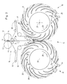
- Fig. 2 shows a folder with a signature display according to an embodiment of the present invention.
- a spell of material moves vertically along one extending path and passes cutting cylinder 12.
- the cutting cylinder 12 have a or several knives 14 cooperating with cutting bar 13 to obtain signatures cut off from the leading part of the material web.
- the clipped signatures are conveyed into a system of belts 15.
- the straps 15 include a left one Conveyor belt 16 and a right conveyor belt 17, which also entry rollers 31 and Have exit rollers 32.
- the belts are tightened by tensioning rollers 30.
- the Exit rollers 32 of the conveyor belts 16, 17 are in a signature input area 27 attached and z. B. may be staggered.
- the signature entrance area 27 is formed by the respective envelopes 20, 21 of the paddle wheel arrangements 18, 19.
- the paddle wheel assemblies 18, 19 rotate about axes of rotation 22, 23 in respective Directions 26. Since the envelopes 20, 21 of the paddle wheel assemblies 18, 19 each other overlap, every second signature ejected by the conveyor belts 16, 17 enters one Paddle wheel pocket 28 of the paddle wheel assemblies 18, 19 in a manner as shown in U.S. Patent No. 5,112,033 and the entire contents of which are incorporated herein by reference is taken.
- the paddle wheel arrangements 18, 19 rotating about the axes of rotation 22, 23 include each have a plurality of blades 29 with their respective edges Form paddle wheel pockets 28.
- Each of the paddle wheel assemblies 18, 19 is one Wipers 24, 25 assigned to those previously inserted into the paddle wheel pockets 28 Remove signatures smoothly.
- the wipers 24, 25 each have a curved one Surface that comes into contact with the leading edge of a signature while it is is removed from the pockets 28. As shown in Fig. 2, the wipers are in the lower Area of the paddle wheel arrangements 18, 19 arranged.
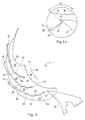
- FIG. 3 shows a segment 33 of a paddle wheel arrangement with a plurality of Bucket blades and paddle wheel pockets located on their circumference.
- the Segment 33 has a curved contact surface 36 for fastening on a around the Rotation axis 23 rotating disc-shaped element.
- the segment 33 comprises four Bucket blades 29, the bucket wheel pockets 28 with a respective entry section 27 form.
- the bucket wheel pockets 28 are each of a first front surface 35 and one second rear surface 34 is formed.
- the rear surface 34 has a series of Curvatures to allow a gentle and unobstructed removal of one previously in the To achieve paddle wheel pocket 28 inserted signature, while segment 33 is around the axis 23 rotates.
- the front surface 35 comprises at least two relief sections 38, 39.
- the relief sections 38, 39 are the relief sections 38, 39 as recesses in of the front surface 35.
- the relief sections 38, 39 have one raised portion 40, the at least a first narrow passage between the Forms recesses in the paddle wheel pocket 28.
- relief sections 38, 39 and 40 shown at locations along the first front surface 35, i.e. within the first Half of the distance from the bottom 37 of a paddle wheel pocket 28 to the signature rear edge 45 (see Fig. 4) are arranged.
- an interchangeable segment 52 with Relief sections 38, 39 can be provided (see dashed lines in Fig. 3), so that a raised part 40 afterwards in each paddle wheel pocket of an existing one Paddle wheel can be fitted.
- the interchangeable segment 52 can be anything conventional fasteners are fixed in place, e.g. B. by as C-clamps molded clamp connections that attach to segment 52 and to a Existing airfoil can be clamped. Such a construction enables the Invention to apply to existing paddle wheel assemblies and thereby their Improve and increase performance.
- the scraper 25 has a tip 42 and is the segment 33 assigned while it rotates about its axis 23.
- the scraper 25 has one curved surface around the signatures that are contacted on their leading edge to be freely removed from the pockets 28 during the rotation of the paddle wheel. It can a stationary scraper can be used, but it will be clear to those skilled in the art that also adjustable scrapers, their position relative to the rear edge of the paddle wheel bag is adjustable, can be used.
- FIG. 3a also shows details of a paddle wheel pocket 28.
- the Bucket wheel bag tight, d. H. slit-shaped.
- the width of the bag for example, varies along at least part of the pocket length between 1.8 mm (0.07 inch) and 2.3 mm (0.09 inch) and is intended for the usual thicknesses of the signatures.
- This narrow width extends over at least a portion of the paddle wheel pocket 28 toward the bottom the bag (e.g., at least 3.8 cm (1.5 inches) along one side of the bag Pocket bottom from extending length), but this width can also extend and the first narrow passage between relief sections 38, 39 and any one enclose another part of the paddle wheel bag.
- Such a construction allows one further dispersal of the kinetic energy before the leading edge of the signature Pocket bottom 37 contacted.
- the narrow passage also serves the signature leading edge effectively stiffen so that they are stronger when they come into contact with the pocket bottom 37 Can withstand impact forces.
- the scraper tip 42 is oriented on the paddle wheel pocket 28.
- the Scraper tip 42 acts at an angle 41 with the rear edge 34 of the paddle wheel pocket together (i.e., an angle that is tangent to the trailing edge 34 and an edge of the Wipers running lines is determined).
- the Angle 41 selected which is a gentle and unobstructed stripping of the signature from the Paddle wheel bag ensures d. that is, an angle of approximately 95 to 100 degrees is chosen.
- the contact angle 41 is retained while the signature leading edge and the scraper tip 42 cross each other, at least for part of the Paddlewheel / wiper crossing (e.g. by approximately 25 degrees of rotation of the Paddle wheel arrangement).
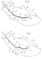
- FIG. 4 is an illustration of a segment 33 similar to the illustration shown in FIG. 3, but the former shows the various states in which a signature according to an exemplary embodiment of the present invention comes to lie.
- the signature 43 has a front edge 44 and a rear edge 45.
- the signature leading edge 44 has contacted the pocket bottom 37.
- the signature 43 gets into contact with the pocket bottom 37 kinked "or unstable state.
- the kinetic energy mentioned above with respect to state 46 is absorbed not only by the pocket bottom 37 but also by the first relief portion 38 and the second relief portion 39.
- the signature 5 further shows the free movement state 46 of a signature.
- the signature was 43 completely inserted into a paddle wheel pocket 28 and is shortly before their contact with the Pocket floor 37 shown.
- the signature 43 is shown as being specific in three Mass portions 49, 50, 51 divided.
- the first mass fraction 49 is in the narrow slot Paddle wheel pocket 28 between the pocket bottom 37 and the first relief section 38 inserted, as indicated by the tangent 49.1.
- a second mass fraction 50 contacts the raised part 40, as indicated by the tangent 50.1.
- a third Mass fraction 51 contacts the front surface 35 of the bucket wheel pocket 28 as through the tangent 51.1 indicated.
Landscapes
- Engineering & Computer Science (AREA)
- Mechanical Engineering (AREA)
- Discharge By Other Means (AREA)
- Pile Receivers (AREA)
- Delivering By Means Of Belts And Rollers (AREA)
- Folding Of Thin Sheet-Like Materials, Special Discharging Devices, And Others (AREA)
Abstract
Description
- Fig. 1
- ein herkömmliches Profil einer Schaufelradtasche;
- Fig. 2
- eine detaillierte Darstellung einer Signaturauslage in einem Falzapparat;
- Fig. 3
- ein Profil einer Schaufelradtasche gemäß einem Ausführungsbeispiel der vorliegenden Erfindung;
- Fig. 3a
- die Spitze eines Abstreifers, die mit einer Schaufelradtasche gemäß einem Ausführungsbeispiel der vorliegenden Erfindung zusammenwirkt;
- Fig. 4
- eine exemplarische Reihenfolge der verschiedenen Zustände, in denen sich eine Signatur beim Aufschlag in einer Tasche befindet; und
- Fig. 5 und 6
- eine Darstellung einer in drei verschiedene Massenanteile unterteilten Signatur, in welcher die Verformung der Signatur während der Zerstreuung kinetischer Energie durch tangentiale Linien gezeigt ist.
- 4
- Profil der Schaufelradtasche 6 (Fig. 1)
- 5
- Signatur (Fig. 1)
- 6
- Schaufelradtasche (Fig. 1)
- 8
- Drehachse (Fig. 1)
- 9
- Segment (Fig. 1)
- 12
- Schneidzylinder (Fig. 2)
- 13
- Schneidbalken (Fig. 2)
- 14
- Messer (Fig. 2)
- 15
- Bändersystem (Fig. 2)
- 16
- linkes Förderband (Fig. 2)
- 17
- rechtes Förderband (Fig. 2)
- 18
- Schaufelradanordnung (Fig. 2)
- 19
- Schaufelradanordnung (Fig. 2)
- 20
- Hüllkurve (Fig. 2)
- 21
- Hüllkurve (Fig. 2)
- 22
- Drehachse (Fig. 2)
- 23
- Drehachse (Fig. 2)
- 24
- Abstreifer (Fig. 2)
- 25
- Abstreifer (Fig. 2)
- 26
- Richtung (Fig. 2)
- 27
- Eintrittsabschnitt der Taschen 28
- 28
- Schaufelradtasche
- 29
- Schaufelblätter
- 30
- Spannrollen
- 31
- Eintrittswalzen
- 32
- Austrittswalzen
- 33
- Segment (Fig. 3a)
- 34
- hintere Oberfläche der Tasche 28
- 35
- vordere Oberfläche der Tasche 28
- 36
- Anlagefläche (Fig. 3)
- 37
- Boden der Schaufelradtasche 28
- 38
- Reliefabschnitt
- 39
- Reliefabschnitt
- 40
- erhabener Teil der Reliefabschnitte
- 41
- Kontaktwinkel
- 42
- Spitze des Abstreifers 25
- 43
- Signatur
- 44
- Signaturvorderkante
- 45
- Signaturhinterkante
- 46
- Zustand der Signatur 43 (freier Bewegungszustand)
- 47
- Zustand der Signatur 43 (geknickter Zustand)
- 48
- Zustand der Signatur 43 (freier Bewegungszustand)
- 49
- Massenanteil der Signatur 43
- 49.1
- Tangente
- 49.2
- Tangente
- 50
- Massenanteil der Signatur 43
- 50.1
- Tangente
- 50.2
- Tangente
- 50.3
- Tangente
- 51
- Massenanteil der Signatur 43
- 51.1
- Tangente
- 51.2
- Tangente
- 52
- austauschbares Segment
Claims (17)
- Vorrichtung zur Auslage von Signaturen, mit mindestens einer Schaufelradanordnung (18, 19), die eine Vielzahl von durch Schaufelradtaschen (28)voneinander beabstandeten Schaufelblättern (29) aufweist, deren Flächen eine jeweilige Schaufelradtasche (28) bilden, wobei jede Schaufelradtasche (28) eine erste Oberfläche (35) umfaßt, die mindestens einen einen erhabenen Teil (40) der Schaufelradtasche (28) bildenden Reliefabschnitt (38, 39) aufweist, der für die Energiezerstreuung der Signatur (43) sorgt.
- Vorrichtung nach Anspruch 1,
dadurch gekennzeichnet,
daß die erste Oberfläche (35) und der Boden (37) einer jeden Tasche (28) Energie von der Signatur (43) absorbieren. - Vorrichtung nach Anspruch 1,
dadurch gekennzeichnet,
daß die erste Oberfläche (35) eine vordere Oberfläche der Schaufelradtasche (28) ist. - Vorrichtung nach Anspruch 3,
dadurch gekennzeichnet,
daß die erste Oberfläche (35) derart gestaltet ist, daß sie als ein austauschbares Segment (33) an die Schaufelblätter (29) montiert werden kann. - Vorrichtung nach Anspruch 1,
dadurch gekennzeichnet,
daß sich der erhabene Teil (40) von der ersten Oberfläche (35) zu einer zweiten Oberfläche (34) der Schaufelradtasche (28) erstreckt. - Vorrichtung nach Anspruch 3,
dadurch gekennzeichnet,
daß die erste Oberfläche (35) mindestens zwei Reliefabschnitte umfaßt. - Vorrichtung nach Anspruch 6,
dadurch gekennzeichnet,
daß der erhabene Teil (40) sich zwischen zwei Reliefabschnitten befindet. - Vorrichtung nach Anspruch 3,
dadurch gekennzeichnet,
daß mindestens zwei Reliefabschnitte an einer Stelle entlang der ersten Oberfläche (35) plaziert ist, die innerhalb der ersten Hälfte eines Abstandes vom Boden (37) der Schaufelradtasche (28) zur Hinterkante (45) der Signatur (43) liegt. - Vorrichtung nach Anspruch 1,
dadurch gekennzeichnet,
daß die Oberflächen (35, 34) derart gestaltet sind, so daß die Signatur (43) in einer Position plaziert werden kann, in welcher sie sich in einem energiedissipierenden Zustand unter ihrer eigenen Masse befindet. - Vorrichtung nach Anspruch 1,
dadurch gekennzeichnet,
daß die zweite Oberfläche (34) einer jeden Schaufelradtasche (28) eine Reihe von Krümmungen umfaßt. - Vorrichtung nach Anspruch 10,
dadurch gekennzeichnet,
daß die zweite Oberfläche (34) eine hintere Oberfläche der Schaufelradtasche (28) ist. - Vorrichtung nach Anspruch 1, welche ferner einen der mindestens einen Schaufelradanordnung (18, 19) zugeordneten Abstreifer (24, 25) umfaßt.
- Vorrichtung nach Anspruch 12,
dadurch gekennzeichnet,
daß der Abstreifer (24, 25) die hintere Oberfläche (34) der Schaufelradtasche (28) in einem Winkel von zwischen ca. 95 und 100 Grad durchkreuzt. - Vorrichtung nach Anspruch 13,
dadurch gekennzeichnet,
daß der Abstreifer (24, 25) die hintere Oberfläche (34) der Schaufelradtasche (28) in dem genannten Winkel während einer Drehbewegung der Schaufelradanordnung (18, 19) von mindestens 25 Grad durchkreuzt. - Vorrichtung nach Anspruch 1,
dadurch gekennzeichnet,
daß die Schaufelradtasche (28) entlang mindestens eines Teils ihrer Länge in Richtung des Bodens (37) der Schaufelradtasche (28) von enger Beschaffenheit ist. - Vorrichtung nach Anspruch 15,
dadurch gekennzeichnet,
daß die Breite der Schaufelradtasche (28) entlang mindestens des genannten Teils ihrer Länge zwischen ca. 1,8 mm (0.07 inch) und 2.3 mm (0.09 inch) variiert. - Vorrichtung nach Anspruch 15,
dadurch gekennzeichnet,
daß der genannte Teil der Länge sich mindestens 3,8 cm (1.5 inches) von dem Boden (37) der Schaufelradtasche (28) erstreckt.
Applications Claiming Priority (2)
| Application Number | Priority Date | Filing Date | Title |
|---|---|---|---|
| US08/749,889 US5730435A (en) | 1996-11-18 | 1996-11-18 | Apparatus for absorbing energy during signature delivery |
| US749889 | 1996-11-18 |
Publications (3)
| Publication Number | Publication Date |
|---|---|
| EP0842884A2 true EP0842884A2 (de) | 1998-05-20 |
| EP0842884A3 EP0842884A3 (de) | 1998-08-05 |
| EP0842884B1 EP0842884B1 (de) | 2002-09-18 |
Family
ID=25015641
Family Applications (1)
| Application Number | Title | Priority Date | Filing Date |
|---|---|---|---|
| EP97117933A Expired - Lifetime EP0842884B1 (de) | 1996-11-18 | 1997-10-16 | Vorrichtung zum Absorbieren von Energie während der Auslage von Signaturen |
Country Status (4)
| Country | Link |
|---|---|
| US (1) | US5730435A (de) |
| EP (1) | EP0842884B1 (de) |
| JP (1) | JPH10157902A (de) |
| DE (1) | DE59708250D1 (de) |
Cited By (1)
| Publication number | Priority date | Publication date | Assignee | Title |
|---|---|---|---|---|
| US9193553B2 (en) | 2012-04-16 | 2015-11-24 | Giesecke & Devrient Gmbh | Stacker wheel for stacking sheets |
Families Citing this family (11)
| Publication number | Priority date | Publication date | Assignee | Title |
|---|---|---|---|---|
| DE19813139C1 (de) * | 1998-03-25 | 1999-09-23 | Schober Werkzeug & Maschbau | Transportvorrichtung |
| US6231044B1 (en) | 1998-12-29 | 2001-05-15 | Quad/Tech, Inc. | Delivery apparatus for a printing press |
| US6247692B1 (en) * | 1999-04-12 | 2001-06-19 | Quad/Tech, Inc. | Signature delivery apparatus including two rotating buckets |
| US6131903A (en) * | 1999-07-20 | 2000-10-17 | Quad/Tech, Inc. | Signature stripping mechanism |
| US7470102B2 (en) * | 2001-07-27 | 2008-12-30 | C.G. Bretting Manufacturing Co., Inc. | Apparatus and method for insertion of separating means into a forming stack of sheets discharged from a starwheel assembly |
| US6832886B2 (en) * | 2001-07-27 | 2004-12-21 | C. G. Bretting Manufacturing Co., Inc. | Apparatus and method for stacking sheets discharged from a starwheel assembly |
| US6877740B2 (en) | 2003-07-30 | 2005-04-12 | C.G. Bretting Manufacturing Company, Inc. | Starwheel feed apparatus and method |
| CH705575B1 (de) * | 2008-06-11 | 2013-04-15 | Ferag Ag | Einsteckvorrichtung und Einsteckverfahren. |
| JP5132544B2 (ja) * | 2008-12-27 | 2013-01-30 | 株式会社東芝 | 光学的文字読取装置 |
| JP2010163237A (ja) * | 2009-01-14 | 2010-07-29 | Toshiba Corp | 回転搬送体、紙葉類処理装置及び回転搬送体の製造方法 |
| DE102011010923A1 (de) * | 2011-02-10 | 2012-08-16 | Giesecke & Devrient Gmbh | Vorrichtung zum Stapeln von Blattgut |
Family Cites Families (8)
| Publication number | Priority date | Publication date | Assignee | Title |
|---|---|---|---|---|
| DE3232348A1 (de) * | 1982-08-31 | 1984-03-01 | GAO Gesellschaft für Automation und Organisation mbH, 8000 München | Vorrichtung zum stapeln von blattfoermigen gegenstaenden |
| DD264190A1 (de) * | 1987-09-04 | 1989-01-25 | Polygraph Leipzig | Schaufelradausleger zur schuppenauslage von druckprodukten |
| DE3910333C1 (de) * | 1989-03-30 | 1990-03-22 | Maschinenfabrik Wifag, Bern, Ch | |
| US5112033A (en) * | 1990-05-09 | 1992-05-12 | Harris Graphics Corporation | Folder apparatus for a web-fed printing press |
| FR2664581A1 (fr) * | 1990-07-12 | 1992-01-17 | Dassault Electronique | Dispositif de traitement de titres tels que des billets de banque, avec roue a aubes a mouvement discontinu. |
| US5180160A (en) * | 1991-08-12 | 1993-01-19 | Heidelberg Harris Gmbh | Delivery device in the folding apparatus of a rotary printing press |
| US6276681B1 (en) * | 1995-04-26 | 2001-08-21 | Heidelberg Harris Inc. | Product delivery apparatus having replaceable elements |
| US5615878A (en) * | 1995-08-15 | 1997-04-01 | Heidelberg Harris Inc. | Method and apparatus for accelerating and diverting flat products |
-
1996
- 1996-11-18 US US08/749,889 patent/US5730435A/en not_active Expired - Lifetime
-
1997
- 1997-10-16 EP EP97117933A patent/EP0842884B1/de not_active Expired - Lifetime
- 1997-10-16 DE DE59708250T patent/DE59708250D1/de not_active Expired - Lifetime
- 1997-11-18 JP JP9316884A patent/JPH10157902A/ja active Pending
Cited By (1)
| Publication number | Priority date | Publication date | Assignee | Title |
|---|---|---|---|---|
| US9193553B2 (en) | 2012-04-16 | 2015-11-24 | Giesecke & Devrient Gmbh | Stacker wheel for stacking sheets |
Also Published As
| Publication number | Publication date |
|---|---|
| EP0842884B1 (de) | 2002-09-18 |
| EP0842884A3 (de) | 1998-08-05 |
| US5730435A (en) | 1998-03-24 |
| DE59708250D1 (de) | 2002-10-24 |
| JPH10157902A (ja) | 1998-06-16 |
Similar Documents
| Publication | Publication Date | Title |
|---|---|---|
| EP0827931B1 (de) | Vorrichtung und Verfahren zum dynamischen Führen von flachen produkten | |
| DE2643709A1 (de) | Sortiervorrichtung fuer ungeordnet verteiltes stueckgut | |
| DE69503686T2 (de) | Verfahren und Vorrichtung zum Drehen von Produkten wie grafischen Produkten | |
| EP0842884B1 (de) | Vorrichtung zum Absorbieren von Energie während der Auslage von Signaturen | |
| EP0535318B1 (de) | Auslageeinrichtung in dem Falzapparat einer Rotationsdruckmaschine | |
| DE3718206A1 (de) | Vorrichtung zum foerdern und drehen von papierstapeln | |
| DD264190A1 (de) | Schaufelradausleger zur schuppenauslage von druckprodukten | |
| EP0087724B1 (de) | Vorrichtung zum Aufbringen eines Leimstreifens auf eine bewegte Materialbahn | |
| DE19703130C2 (de) | Einrichtung zum Auslenken von Signaturen mittels rotierender Flächen | |
| DE4106084A1 (de) | Rotationsquerschneider | |
| EP0820949A1 (de) | Produktführungseinrichtung am Schneidzylinderpaar eines Falzapparates | |
| EP0709326B1 (de) | Verfahren und Vorrichtung zum Beschriften gefalteter Druckereiprodukte auf einer innenliegenden Seite | |
| DE19839433A1 (de) | Vorrichtung zum Abbremsen und zur geschuppten Auslage von Signaturen | |
| EP2050562A1 (de) | Wellpappe-Streifen-Wende-Vorrichtung | |
| EP0699612A2 (de) | Falzapparat | |
| DE10047041A1 (de) | Vorrichtung und Verfahren zum Schneiden und Umlenken von Signaturen | |
| EP0770571A2 (de) | Vorrichtung zum vorübergehenden Führen aufeinanderfolgender Bogen | |
| EP2655078B1 (de) | Verfahren zum anbringen wenigstens eines umfassungselements an einer flächigen produktzusammenstellung sowie umfassungselement-applikationsvorrichtung zur durchführung des verfahrens | |
| DE1654867B2 (de) | Vorrichtung zum nobben von fischen | |
| DE19711235A1 (de) | Vorrichtung für die Produktauslage mit einem Produktaufnahmebereich | |
| WO2003016187A1 (de) | Vorrichtung zum querschneiden von materialbahnen, insbesondere papier-oder kartonbahnen | |
| DE2425736C3 (de) | Vorrichtung zum aufeinanderfolgenden Zuführen von Aufzeichnungsblättern | |
| EP1110894B1 (de) | Verfahren und Vorrichtung zum Falzen von Materialbogen | |
| EP0462372B1 (de) | Falzapparat für eine Rollenrotationsdruckmaschine | |
| DE202004005827U1 (de) | Vorrichtung zum Querschneiden von Materialbahnen, insbesondere Papier- oder Kartonbahnen |
Legal Events
| Date | Code | Title | Description |
|---|---|---|---|
| PUAI | Public reference made under article 153(3) epc to a published international application that has entered the european phase |
Free format text: ORIGINAL CODE: 0009012 |
|
| 17P | Request for examination filed |
Effective date: 19971016 |
|
| AK | Designated contracting states |
Kind code of ref document: A2 Designated state(s): CH DE FR GB IT LI |
|
| AX | Request for extension of the european patent |
Free format text: AL;LT;LV;RO;SI |
|
| PUAL | Search report despatched |
Free format text: ORIGINAL CODE: 0009013 |
|
| AK | Designated contracting states |
Kind code of ref document: A3 Designated state(s): AT BE CH DE DK ES FI FR GB GR IE IT LI LU MC NL PT SE |
|
| AX | Request for extension of the european patent |
Free format text: AL;LT;LV;RO;SI |
|
| AKX | Designation fees paid |
Free format text: CH DE FR GB IT LI |
|
| RBV | Designated contracting states (corrected) |
Designated state(s): CH DE FR GB IT LI |
|
| 17Q | First examination report despatched |
Effective date: 20000929 |
|
| GRAG | Despatch of communication of intention to grant |
Free format text: ORIGINAL CODE: EPIDOS AGRA |
|
| GRAG | Despatch of communication of intention to grant |
Free format text: ORIGINAL CODE: EPIDOS AGRA |
|
| GRAH | Despatch of communication of intention to grant a patent |
Free format text: ORIGINAL CODE: EPIDOS IGRA |
|
| GRAH | Despatch of communication of intention to grant a patent |
Free format text: ORIGINAL CODE: EPIDOS IGRA |
|
| GRAA | (expected) grant |
Free format text: ORIGINAL CODE: 0009210 |
|
| AK | Designated contracting states |
Kind code of ref document: B1 Designated state(s): CH DE FR GB IT LI |
|
| PG25 | Lapsed in a contracting state [announced via postgrant information from national office to epo] |
Ref country code: IT Free format text: LAPSE BECAUSE OF FAILURE TO SUBMIT A TRANSLATION OF THE DESCRIPTION OR TO PAY THE FEE WITHIN THE PRE;WARNING: LAPSES OF ITALIAN PATENTS WITH EFFECTIVE DATE BEFORE 2007 MAY HAVE OCCURRED AT ANY TIME BEFORE 2007. THE CORRECT EFFECTIVE DATE MAY BE DIFFERENT FROM THE ONE RECORDED.SCRIBED TIME-LIMIT Effective date: 20020918 Ref country code: GB Free format text: LAPSE BECAUSE OF FAILURE TO SUBMIT A TRANSLATION OF THE DESCRIPTION OR TO PAY THE FEE WITHIN THE PRESCRIBED TIME-LIMIT Effective date: 20020918 Ref country code: FR Free format text: LAPSE BECAUSE OF FAILURE TO SUBMIT A TRANSLATION OF THE DESCRIPTION OR TO PAY THE FEE WITHIN THE PRESCRIBED TIME-LIMIT Effective date: 20020918 |
|
| REG | Reference to a national code |
Ref country code: GB Ref legal event code: FG4D Free format text: NOT ENGLISH |
|
| REG | Reference to a national code |
Ref country code: CH Ref legal event code: EP |
|
| REF | Corresponds to: |
Ref document number: 59708250 Country of ref document: DE Date of ref document: 20021024 |
|
| GBV | Gb: ep patent (uk) treated as always having been void in accordance with gb section 77(7)/1977 [no translation filed] |
Effective date: 20020918 |
|
| EN | Fr: translation not filed | ||
| PLBE | No opposition filed within time limit |
Free format text: ORIGINAL CODE: 0009261 |
|
| STAA | Information on the status of an ep patent application or granted ep patent |
Free format text: STATUS: NO OPPOSITION FILED WITHIN TIME LIMIT |
|
| 26N | No opposition filed |
Effective date: 20030619 |
|
| PGFP | Annual fee paid to national office [announced via postgrant information from national office to epo] |
Ref country code: DE Payment date: 20101027 Year of fee payment: 14 Ref country code: CH Payment date: 20101025 Year of fee payment: 14 |
|
| REG | Reference to a national code |
Ref country code: CH Ref legal event code: PL |
|
| PG25 | Lapsed in a contracting state [announced via postgrant information from national office to epo] |
Ref country code: LI Free format text: LAPSE BECAUSE OF NON-PAYMENT OF DUE FEES Effective date: 20111031 Ref country code: CH Free format text: LAPSE BECAUSE OF NON-PAYMENT OF DUE FEES Effective date: 20111031 Ref country code: DE Free format text: LAPSE BECAUSE OF NON-PAYMENT OF DUE FEES Effective date: 20120501 |
|
| REG | Reference to a national code |
Ref country code: DE Ref legal event code: R119 Ref document number: 59708250 Country of ref document: DE Effective date: 20120501 |