US5112033A - Folder apparatus for a web-fed printing press - Google Patents
Folder apparatus for a web-fed printing press Download PDFInfo
- Publication number
- US5112033A US5112033A US07/782,757 US78275791A US5112033A US 5112033 A US5112033 A US 5112033A US 78275791 A US78275791 A US 78275791A US 5112033 A US5112033 A US 5112033A
- Authority
- US
- United States
- Prior art keywords
- fan
- fans
- blades
- assemblies
- tips
- Prior art date
- Legal status (The legal status is an assumption and is not a legal conclusion. Google has not performed a legal analysis and makes no representation as to the accuracy of the status listed.)
- Expired - Lifetime
Links
Images


Classifications
-
- B—PERFORMING OPERATIONS; TRANSPORTING
- B65—CONVEYING; PACKING; STORING; HANDLING THIN OR FILAMENTARY MATERIAL
- B65H—HANDLING THIN OR FILAMENTARY MATERIAL, e.g. SHEETS, WEBS, CABLES
- B65H29/00—Delivering or advancing articles from machines; Advancing articles to or into piles
- B65H29/58—Article switches or diverters
- B65H29/60—Article switches or diverters diverting the stream into alternative paths
-
- B—PERFORMING OPERATIONS; TRANSPORTING
- B65—CONVEYING; PACKING; STORING; HANDLING THIN OR FILAMENTARY MATERIAL
- B65H—HANDLING THIN OR FILAMENTARY MATERIAL, e.g. SHEETS, WEBS, CABLES
- B65H29/00—Delivering or advancing articles from machines; Advancing articles to or into piles
- B65H29/38—Delivering or advancing articles from machines; Advancing articles to or into piles by movable piling or advancing arms, frames, plates, or like members with which the articles are maintained in face contact
- B65H29/40—Members rotated about an axis perpendicular to direction of article movement, e.g. star-wheels formed by S-shaped members
-
- B—PERFORMING OPERATIONS; TRANSPORTING
- B65—CONVEYING; PACKING; STORING; HANDLING THIN OR FILAMENTARY MATERIAL
- B65H—HANDLING THIN OR FILAMENTARY MATERIAL, e.g. SHEETS, WEBS, CABLES
- B65H2404/00—Parts for transporting or guiding the handled material
- B65H2404/20—Belts
- B65H2404/23—Belts with auxiliary handling means
- B65H2404/231—Belts with auxiliary handling means pocket or gripper type
- B65H2404/2311—Belts with auxiliary handling means pocket or gripper type integrally attached to or part of belt material
-
- B—PERFORMING OPERATIONS; TRANSPORTING
- B65—CONVEYING; PACKING; STORING; HANDLING THIN OR FILAMENTARY MATERIAL
- B65H—HANDLING THIN OR FILAMENTARY MATERIAL, e.g. SHEETS, WEBS, CABLES
- B65H2404/00—Parts for transporting or guiding the handled material
- B65H2404/60—Other elements in face contact with handled material
- B65H2404/65—Other elements in face contact with handled material rotating around an axis parallel to face of material and perpendicular to transport direction, e.g. star wheel
- B65H2404/657—Means for varying the space between the elements
-
- B—PERFORMING OPERATIONS; TRANSPORTING
- B65—CONVEYING; PACKING; STORING; HANDLING THIN OR FILAMENTARY MATERIAL
- B65H—HANDLING THIN OR FILAMENTARY MATERIAL, e.g. SHEETS, WEBS, CABLES
- B65H2404/00—Parts for transporting or guiding the handled material
- B65H2404/60—Other elements in face contact with handled material
- B65H2404/65—Other elements in face contact with handled material rotating around an axis parallel to face of material and perpendicular to transport direction, e.g. star wheel
- B65H2404/659—Other elements in face contact with handled material rotating around an axis parallel to face of material and perpendicular to transport direction, e.g. star wheel particular arrangement
- B65H2404/6591—Pair of opposite elements rotating around parallel axis, synchronously in opposite direction
Definitions
- the invention relates to a folder apparatus for a web-fed printing press and, more specifically, to a folder apparatus located downstream of the printing press in the direction of travel of a printed product.
- a paper web which has been fed through a web-fed rotary printing press, is printed, it is fed to a folder apparatus wherein processing of the printed products (folding, cutting and separating) occurs.
- a focal point of the invention is concerned with a printed product delivery system which permits the printed product stream conducted through the folder apparatus to divide into a plurality of printed product streams for the purpose of delivering the printed product.
- the printed product delivery is effected by means of one or more contra-revolving assemblies such as fan assemblies or arrangements which take up the printed product and deposit it on a conveyor belt for further processing.
- contra-revolving assemblies such as fan assemblies or arrangements which take up the printed product and deposit it on a conveyor belt for further processing.
- two fan arrangements can be provided with respect to one printed product stream, the fan arrangements, respectively, having a printed product alternatingly fed thereto.
- no diverter for channeling the printed product stream to the two fan arrangements is provided in U.S. Pat. No. 3,762,697.
- the spacing between the mutually opposing axes of the fan arrangements in the latter patent is smaller than the diameter of each of the identical fan arrangements.
- the paddles of the first fan arrangement are arranged so as to be offset laterally from the paddles of the second fan arrangement, so as to prevent any collision of the oppositely disposed paddles.
- the feed of the printed products occurs in the middle between the parallel axes of the fan arrangements.
- the first or the second fan arrangement can take over the oncoming printed product and deliver it.
- a disadvantage of the latter construction is that the printed product virtually drops in a free fall without guidance into the respective paddles of a fan arrangement. Such printed products falling without guidance can, for example, pass between the paddles of the fan arrangements which are disposed axially offset from one another or can become jammed between the paddles, which results in damage to the printed product.
- a folder apparatus for a web-fed printing press having a printed-product delivery comprising two assemblies, respectively, revolvable in opposite directions and including respective receiving means formed with pockets for receiving a printed product therein, the respective receiving means of each of the assemblies being displaceable along respective endless paths as the assemblies revolve, the receiving means of both of the assemblies being on a collision course with one another so as to be collidable at a given location of the endless paths, and collision-preventing means included in each of the assemblies for preventing a collision at the location between the receiving means in one of the assemblies and the receiving means in the other of the assemblies.
- a folder apparatus of a web-fed printing press having a printed-product delivery comprising two fan assemblies, respectively, formed of a rotatable body having a substantially cylindrical configuration and having respective rotational axes disposed alongside and spaced from one another, each of the fan arrangements being formed with a multiplicity of blades having tips located at a circumference of the respective fan arrangement, respective mutually adjacent pairs of the blades defining therebetween a pocket for receiving a printed product therein, the rotational axes being spaced a distance from one another which is less than the sum of the radii of the cylindrically configured rotatable bodies so that the circumferences thereof mutually intersect, the fan assembly having means for preventing the respective blade tips of the fans from colliding.
- each of the two fan arrangements is formed of a plurality of mutually adjacent fans spaced-apart from one another on a common axis, the respective common axis of each of the two fan arrangements being disposed parallel to the common axis of the other, each of the fans of one of the fan arrangements being disposed adjacent to and in a respective common plane with a respective one of the fans of the other fan arrangements, each of the fans being formed with blades having tips located at a circumference of the respective fan, the circumferences of the fans in the respective common plane intersecting with one another, and means provided on the fans for preventing a collision of respective blade tips of the fans disposed in the respective common plane.
- the arrangement of the opposing fans to one another offers many advantages with respect to paper transport and handling of the individual products processed in the folder apparatus, respectively.
- the arrangement of the fans it is possible also to guide reliably folded products, such as four-page signatures, for example, which are problematic i.e. thin, light, small-formatted or open at the leading edge thereof, which tend to flutter during transport (especially at very high speeds).
- a folded product which is taken up by the blades of one of the fan assemblies is thus lifted away from the product stream by the succeeding blade tips of the opposing other fan assembly, and additionally displaced in the direction of the first-mentioned fan assembly.
- a minimum spacing, if necessary or desirable, is thereby produced advantageously between the folded products in the product stream, because the following printed products can then be ideally taken up immediately from the next fan assembly.
- the folded product can additionally be stabilized.
- the blades of the fans are formed with recesses at a radially outer region thereof, for receiving therein the tips of the blades of the fans disposed therewith in the respective common planes.
- the blades are formed with a given curvature
- the collision preventing means include a resilient covering for the respective recess formed in the blades, the resilient covering having substantially the same curvature as the given curvature of the respective blade and being movable into the respective recess.
- the resilient covering is a leaf-spring element.
- the recess has its greatest depth closest to a free end of the respective blade tip and is formed with an undercut portion thereat, the leaf-spring element being fixed to the respective blade tip at a location of the recess farthest from the free end of the respective blade tip and having, in turn, a free end yieldingly received in the undercut portion of the recess.
- the recess is formed in only one side of each of the respective blades of the fan, and the tip of each of the respective blades of the other fan is correspondingly formed so as to be accommodated in the recess.
- the recess has a depth which is a fraction of the thickness of the blade, and an outermost part of the tips of the blades has a reduced thickness substantially corresponding to the depth of the recess so as to afford a contact-free passage of the outermost parts of the tips of the blades, respectively, through the recess.
- the recesses are formed in only part of the thickness of the blade tips and sufficient clearance between the defining surfaces of the recesses and the corresponding tip portions of reduced thickness permit a trouble-free interengagement of the opposing fans.
- respective pairs of the blades of the fans define pockets therebetween for receiving printed products therein
- the folder apparatus includes means for successively feeding a stream of cut printed products directly to the fan assemblies, the feeding means comprising tape rollers carrying transport tapes and including lowermost tape rollers projecting downwardly into the fans for effecting a positive, high-speed placement of the printed products into the respective pockets.
- the blades have a slide-resistant material (such as foamed material or the like) thereon for braking an oncoming printed product. Due to this feature, the folded product can be additionally braked, in an advantageous manner, the instant the tip of the respective opposing fan comes into contact with the printed product.
- a slide-resistant material such as foamed material or the like
- the tips of the blades of one of the fan arrangements are movable towards and away from the tips of the blades of the other of the fan arrangements.
- a slide-resistant material is disposed in the pockets for the printed product so as to effect a braking of the printed product therein, in an advantageous manner.
- At least a portion of the tips of the blades is movably disposed on the blades, and means are provided for actuating the movable portion of the tips.
- a printed product delivery comprising two fan assemblies, respectively, formed of a rotatable body having a substantially cylindrical configuration; and means for successively delivering a stream of cut printed products directly to the fan assemblies, the rotatable bodies having respective rotational axes disposed alongside and spaced from one another a distance less than the sum of the radii of the substantially cylindrically configured bodies so that a mutually overlapping region of the circumferences of the bodies is formed, each of the fan assemblies having a multiplicity of blades defining pockets therebetween for receiving printed products therein and being formed with respective tips extending into the overlapping region of the circumferences for diverting the printed products directly delivered to the fan assemblies alternatingly into a pocket of the one fan assembly and into a pocket of the other fan assembly, and means formed on the fan assemblies for preventing the respective blade tips from colliding.
- the blade tips are pivotally connected to the blades, and including means for alternatingly pivoting the blade tips, respectively, out of the mutually overlapping region of the circumferences so as to prevent collision between the respective blade tips of the respective fan assemblies.
- a folder apparatus of a web-fed printing press having a printed product delivery comprising two fan assemblies, respectively, formed of a rotatable body having a substantially cylindrical configuration and having respective rotational axes disposed parallel to one another, each of the fan assemblies being formed with a multiplicity of blades having tips located at a circumference of the respective fan assembly, respective mutually adjacent pairs of the blades defining therebetween a pocket for receiving a printed product therein, the rotational axes being spaced a distance from one another which is less than the sum of the radii of the substantially cylindrically configured rotatable bodies so that the circumferences mutually intersect, the fan assemblies having means for preventing the respective blade tips of the fans from colliding.
- FIG. 1 is a diagrammatic front elevational view of a folder apparatus constructed in accordance with the invention
- FIG. 2 is a much-enlarged fragmentary view of FIG. 1 showing part of a delivery system of the folder apparatus which includes two fan assemblies;
- FIG. 3 is a view similar that of FIG. 2 of a second embodiment of the fan assemblies wherein the fans thereof are provided with springs;
- FIG. 4 is a diagrammatic end view of the fan assemblies
- FIG. 5 is a view like that of FIG. 3, wherein the springs of the second embodiment of the invention have a modified construction
- FIG. 6 is a diagrammatic perspective view of another embodiment of the fan assemblies, wherein each fan assembly has a substantially cylindrical configuration
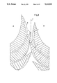
- FIG. 7 is a diagrammatic elevational view of a fourth embodiment of the invention, wherein the delivery system includes assemblies formed as endless belts;
- FIGS. 8 and 8a are views like those of FIGS. 3 and 4, respectively, of a fifth embodiment of the fan assemblies, wherein the fans have non-intersecting circumferences and extensible and retractable blade tips.
- FIGS. 1 and 2 there is shown therein the transport path of a printed product.
- One or more paper webs 14 are conducted over a former 24 and folded. After being folded, the paper web 14 is fed through nips of upper and lower draw rollers 23 and 22, respectively, and guide rollers 21 to a cutting cylinder 20, which severs the printed product from the paper web 14.
- a paper web separating device 25 is provided between the upper draw rollers 23 and the lower draw rollers 22
- the cut and folded printed products are then fed by high-speed conveyor belts or transport tapes 13, which may also be formed as accelerators, to two fan assemblies or arrangements 17 and 18.
- the high-speed transport tapes 13 conduct the printed products to a location in the immediate vicinity of the respective fans 15 and 16 of the fan assemblies 17 and 18.
- FIG. 2 A leading edge 9 of the printed product conveyed and suitably accelerated by the high-speed transport tapes 13 meets the fan blade 3, which is momentarily disposed in a position for receiving the printed product, in the vicinity of a tip 8 of the fan blade 3, and is displaced into a receiving pocket 11 formed by the two blades 1 and 3 of the respective fan 15.
- a tip 6 of the succeeding, oppositely disposed fan blade 2 deflects the printed-product flow from the vertically oncoming flow 14 of printed products into the direction of the fan blade 1, due to which also additional stabilization of the printed product occurs.
- the tip 6 of the fan blade 2 which had previously deflected and stabilized the printed product, dips into a recess 5 formed in the blade 1 following the receiving pocket 11.
- the next printed product is then transported by the high-speed tapes 13 into the vicinity of the tip of the fan blade 2 which had previously caused the deflection of the printed product, and is moved completely into the receiving pocket 12 which is provided therefor. These steps are alternatingly repeated.
- the printed product disposed in the receiving pockets 11 and 12 are slid out of the respective receiving pockets 11 and 12 by a conventional non-illustrated output stripper in a direction opposite to that in which they had been inserted into those receiving pockets and are deposited onto output conveyor belts 26 and 27.
- a spring element or leaf spring 19 as shown in FIG. 3, is provided for covering the respective recess 5, 7, 10.
- the spring element 19 is suitably connected at one end thereof to the respective blade 1 to 4 and, as shown in FIG. 3, is suitably prestressed so that, in the state thereof wherein it is not engaged by the point of an adjacent blade, it follows the contour of the blade to which it is attached. As shown in FIG.
- the free end of the leaf spring element 19 is modified with a suitable bend formed therein so that it may catch or be received in a suitably undercut portion of the recess located at the end thereof of greater depth. This prevents the free end of the leaf spring element 19 from snagging on the printed product as it enters the receiving pocket.
- the respective blade 1 may be provided with a cutout or notch 5 (FIG. 2), which extends over only part of the thickness of the blade 1, as seen in FIG. 4, the tip 6 of the blade 2 located opposite thereto being, in turn, constructed i.e. undercut, in a similar manner (note FIG. 4), so that it can be received in the notch 5 of the blade 1 without collision with the defining walls of the notch 5.
- the lowermost rolls of the tapes 13 are disposed deeply between the fans 15,16 so as to afford a positive high-speed placement of the printed products or signatures into the fan pockets 11.
- FIG. 4 The juxtaposed fans 3 and 4 of the respective fan assemblies 17 and 18 are thus clearly shown in FIG. 4.
- Each of the pairs of juxtaposed fans 15, 16; 29, 30 and 31, 32 are shown clearly arranged in respective common planes extending perpendicularly into the plane of the drawing of FIG. 4.
- the tip 28 of the fan blade 4 engages in the notch 10 of the fan blade 3.
- the fan blade 4 would simultaneously force the spring element 19 into the notch 10 as it i.e. the blade 4, dips into the notch 10
- the fans 15, 16, 29, 30, 31 and 32 of the fan assemblies or arrangements 17 and 18, of which only the fans 15 and 16 are shown in FIG. 1, have a diameter of 36 inches in a given embodiment thereof and are preferably formed of molded plastic material. Of course, they may be formed of any other suitable material as well, and the pockets and notches may be formed of any suitable machining process. Due to the relatively large diameter of the fans, the receiving pockets 11 and 12 may be formed quite deep so that the printed product sliding into the receiving pocket 11 or 12 can travel back over a sufficiently long path on which, in turn, smooth braking, for example, by using a suitable slide retarding material, can be effected.
- a shock-absorbing or impact-damping element, such as foam material, for example, may additionally be applied to the end of the receiving pocket 11, 12, which finally and softly brakes the leading edge 9 of the printed product.
- the leading edge 9 of the printed product which arrives at the end of the receiving pocket 11, 12 has a relatively slow peripheral speed, because the end of the receiving pocket 11, 12 lies near the center of the fan.
- the stationary stripping device which is presented by the included broken lines above the conveyor belts 26 and 27 in FIG. 1, and which is supposed to slide the printed product again out of the receiving pocket 11, 12, thus collides with the leading edge 9 of the printed product at a slow speed so that no damage to the leading edge 9 is anticipated even if very thin printing paper is used.
- the stripping device may be disposed at suitable locations along the axes of the fans constituting each of the fan assemblies, those locations being in the spaces between individual fans of the respective fan assemblies.
- each fan arrangement 40, 41 is, in substance, a cylinder formed with pockets between respective blades and, although not actually shown in the figure, suitable circumferential recesses may be formed in the surface of the substantially cylindrical fan arrangements to accommodate transport tapes and rollers, as well as strippers.
- FIG. 7 illustrates diagrammatically a fourth embodiment of the invention wherein the fan assemblies are in the form of endless belts 51 and 52.
- Blades 53 formed with respective pockets therebetween are secured at selected spaced intervals along the respective endless belts 51 and 52, the alternating delivery of the printed products 14 to the respective pockets 54 of the two fan assemblies 51 and 52, the speed with which the respective drive sprockets 55 for the belts, as well as the spacing of the blades 53 along the endless belts 51 and 52, being controlling factors for slowing down the travel of the products 14.
- the blades 53 may be constructed like any of the blades in the aforedescribed embodiments of the invention.
- the tips 35,36 of the blades 37,38, respectively, of the fans 42 and 43 of two fan arrangements 17' and 18' similar to those of FIGS. 2 and 3, for example, are, however, extensible to divert an oncoming printed product or signature into respective receiving pockets 39, and then retractable so as to avoid any possibility of a collision.
- the circumferences of the fan arrangements 17' and 18', in the retracted condition of the tips 35,36 of the fan blades 37,38 do not intersect i.e. there is a gap 50 between the fan arrangements 17' and 18' as viewed in the retracted condition of the blade tips 35 and 36.
- a suitable mechanism for effecting the extension and retraction of the tips 35,36 is illustrated diagrammatically in FIG. 8, and is made up of a linkage or push rod 44 pivotally connected at one end thereof to the respective pivotal end tip of the blades of those fans located at one side of the respective fan arrangements, the linkage 44 having a cam roller at the other end thereof which follows a suitably configured cam 46 fixed to a stationary side wall of the machine.
- the respective tips of all of the fan blades disposed along the axes of the respective fan arrangements 17' and 18' are connected to one another so as to be extensible and retractable in unison in accordance with the action of the respective cam follower arrangement 44,45.
- the tips 35 and 36 of all the blades 37 and 38 extended as the fans 42 and 43 revolve, in which case the thus formed circumferences of the fan arrangements 17' and 18' at the ends of the blade tips 35 and 36, respectively, would intersect. Consequently, only those tips, respectively, which must be retracted in order to avoid a collision at the intersecting location, would, in fact, be retracted by means of the cam follower arrangement 44,45 and a suitably configured cam 46, for example.
- the tips of the blades may also be formed with suitable recesses such as the recess 5, 7, 10 in the embodiment of FIG. 2, for example, in which case the tips of the blades of the fans 42 and 43 of FIG. 8 need not retract but may remain extended at the location at which they intersect, without collision.
Landscapes
- Engineering & Computer Science (AREA)
- Mechanical Engineering (AREA)
- Discharge By Other Means (AREA)
Abstract
Description
Claims (22)
Priority Applications (1)
| Application Number | Priority Date | Filing Date | Title |
|---|---|---|---|
| US07/782,757 US5112033A (en) | 1990-05-09 | 1991-10-21 | Folder apparatus for a web-fed printing press |
Applications Claiming Priority (2)
| Application Number | Priority Date | Filing Date | Title |
|---|---|---|---|
| US52126390A | 1990-05-09 | 1990-05-09 | |
| US07/782,757 US5112033A (en) | 1990-05-09 | 1991-10-21 | Folder apparatus for a web-fed printing press |
Related Parent Applications (1)
| Application Number | Title | Priority Date | Filing Date |
|---|---|---|---|
| US52126390A Continuation | 1990-05-09 | 1990-05-09 |
Publications (1)
| Publication Number | Publication Date |
|---|---|
| US5112033A true US5112033A (en) | 1992-05-12 |
Family
ID=27060431
Family Applications (1)
| Application Number | Title | Priority Date | Filing Date |
|---|---|---|---|
| US07/782,757 Expired - Lifetime US5112033A (en) | 1990-05-09 | 1991-10-21 | Folder apparatus for a web-fed printing press |
Country Status (1)
| Country | Link |
|---|---|
| US (1) | US5112033A (en) |
Cited By (25)
| Publication number | Priority date | Publication date | Assignee | Title |
|---|---|---|---|---|
| FR2722181A1 (en) * | 1994-07-08 | 1996-01-12 | Heidelberger Druckmasch Ag | FOLDER. |
| US5490666A (en) * | 1994-08-29 | 1996-02-13 | Heidelberger Druchemaschiner Ag | Folder with spring-biased exit roller |
| US5538242A (en) * | 1994-07-08 | 1996-07-23 | Heidelberger Druckmaschinen Ag | Signature aiming device |
| US5558615A (en) * | 1994-08-29 | 1996-09-24 | Heidelberger Druckmaschinen Ag | Modular exit roller assembly |
| FR2733492A1 (en) * | 1995-04-26 | 1996-10-31 | Heidelberger Druckmasch Ag | PRODUCT DISTRIBUTION DEVICE CONTAINING REPLACABLE ELEMENTS |
| US5607146A (en) * | 1996-02-16 | 1997-03-04 | Heidelberger Druckmaschinen Ag | Mechanism for diverting of products in a folding apparatus |
| US5615878A (en) * | 1995-08-15 | 1997-04-01 | Heidelberg Harris Inc. | Method and apparatus for accelerating and diverting flat products |
| US5639083A (en) * | 1994-07-14 | 1997-06-17 | Heidelberger Druckmaschinen Ag | Device for the delivery of folded products |
| US5653428A (en) * | 1995-10-30 | 1997-08-05 | Heidelberger Druckmaschinen Ag | Phase control system for a folder fan |
| US5681254A (en) * | 1994-09-27 | 1997-10-28 | Heidelberg Harris, Inc. | Mechanism for applying a biasing force in a folder apparatus |
| US5702100A (en) * | 1996-03-25 | 1997-12-30 | Heidelberg Harris | Mechanism for diverting signatures by the rotation of surfaces |
| US5730435A (en) * | 1996-11-18 | 1998-03-24 | Heidelberg Harris Inc. | Apparatus for absorbing energy during signature delivery |
| US5865082A (en) * | 1996-09-04 | 1999-02-02 | Heidelberg Harris Inc. | Apparatus for transporting signatures |
| US5975525A (en) * | 1995-07-11 | 1999-11-02 | Koenig & Bauer-Albert Aktiengesellschaft | Paddle wheel for laying out folded products |
| US6231044B1 (en) | 1998-12-29 | 2001-05-15 | Quad/Tech, Inc. | Delivery apparatus for a printing press |
| GB2356189A (en) * | 1999-11-11 | 2001-05-16 | Ibis Integrated Bindery System | Book bindery and trimming apparatus |
| US6247692B1 (en) | 1999-04-12 | 2001-06-19 | Quad/Tech, Inc. | Signature delivery apparatus including two rotating buckets |
| US6302392B1 (en) | 1998-12-29 | 2001-10-16 | Quad/Tech, Inc. | Sheet diverter for collating signatures and a method thereof |
| US6341776B1 (en) | 1996-04-25 | 2002-01-29 | Heidelberger Druckmaschinen Ag | Product delivery apparatus having a product transport receiving area |
| US6439372B1 (en) * | 1998-03-25 | 2002-08-27 | Schober Gmbh Werkzeug - Und Maschinenbau | Conveyor device |
| US6561507B1 (en) | 1997-09-04 | 2003-05-13 | Heidelberger Druckmaschinen Ag | Apparatus for decelerating and shingling signatures |
| US20050124481A1 (en) * | 2003-12-09 | 2005-06-09 | Quad/Tech, Inc. | Printing press folder and folder components |
| US20090038454A1 (en) * | 2007-08-10 | 2009-02-12 | Goss International Americas, Inc. | Printing press folder with parallel process transport tapes |
| EP2484615A2 (en) | 2011-02-08 | 2012-08-08 | Goss International Americas, Inc. | Method and apparatus for diverting printed products into three streams |
| US9302875B2 (en) | 2011-02-22 | 2016-04-05 | Goss International Americas, Inc. | Method and apparatus for diverting signatures in a folder |
Citations (3)
| Publication number | Priority date | Publication date | Assignee | Title |
|---|---|---|---|---|
| DE441782C (en) * | 1922-10-05 | 1927-03-12 | Louis Chambon | Machine for alternating cutting, interfolding and stacking of the paper fed from two webs with two folding wheels interlocking with one another with teeth |
| FR1408247A (en) * | 1964-06-29 | 1965-08-13 | Petits Fils De Leonard Danel | Device for continuously assembling groups of pre-folded prints |
| US3607583A (en) * | 1969-12-24 | 1971-09-21 | Robert C Geschwender | Fabrication of honeycomb-type cellular materials |
-
1991
- 1991-10-21 US US07/782,757 patent/US5112033A/en not_active Expired - Lifetime
Patent Citations (3)
| Publication number | Priority date | Publication date | Assignee | Title |
|---|---|---|---|---|
| DE441782C (en) * | 1922-10-05 | 1927-03-12 | Louis Chambon | Machine for alternating cutting, interfolding and stacking of the paper fed from two webs with two folding wheels interlocking with one another with teeth |
| FR1408247A (en) * | 1964-06-29 | 1965-08-13 | Petits Fils De Leonard Danel | Device for continuously assembling groups of pre-folded prints |
| US3607583A (en) * | 1969-12-24 | 1971-09-21 | Robert C Geschwender | Fabrication of honeycomb-type cellular materials |
Cited By (37)
| Publication number | Priority date | Publication date | Assignee | Title |
|---|---|---|---|---|
| US5538242A (en) * | 1994-07-08 | 1996-07-23 | Heidelberger Druckmaschinen Ag | Signature aiming device |
| FR2722181A1 (en) * | 1994-07-08 | 1996-01-12 | Heidelberger Druckmasch Ag | FOLDER. |
| US5639083A (en) * | 1994-07-14 | 1997-06-17 | Heidelberger Druckmaschinen Ag | Device for the delivery of folded products |
| US5490666A (en) * | 1994-08-29 | 1996-02-13 | Heidelberger Druchemaschiner Ag | Folder with spring-biased exit roller |
| EP0699612A2 (en) | 1994-08-29 | 1996-03-06 | Heidelberger Druckmaschinen Aktiengesellschaft | Folding apparatus |
| US5558615A (en) * | 1994-08-29 | 1996-09-24 | Heidelberger Druckmaschinen Ag | Modular exit roller assembly |
| DE19519372C2 (en) * | 1994-08-29 | 2000-04-06 | Heidelberger Druckmasch Ag | Modular conveyor belt mechanism |
| US5681254A (en) * | 1994-09-27 | 1997-10-28 | Heidelberg Harris, Inc. | Mechanism for applying a biasing force in a folder apparatus |
| FR2733492A1 (en) * | 1995-04-26 | 1996-10-31 | Heidelberger Druckmasch Ag | PRODUCT DISTRIBUTION DEVICE CONTAINING REPLACABLE ELEMENTS |
| US6276681B1 (en) | 1995-04-26 | 2001-08-21 | Heidelberg Harris Inc. | Product delivery apparatus having replaceable elements |
| US5975525A (en) * | 1995-07-11 | 1999-11-02 | Koenig & Bauer-Albert Aktiengesellschaft | Paddle wheel for laying out folded products |
| US5615878A (en) * | 1995-08-15 | 1997-04-01 | Heidelberg Harris Inc. | Method and apparatus for accelerating and diverting flat products |
| US5653428A (en) * | 1995-10-30 | 1997-08-05 | Heidelberger Druckmaschinen Ag | Phase control system for a folder fan |
| US5607146A (en) * | 1996-02-16 | 1997-03-04 | Heidelberger Druckmaschinen Ag | Mechanism for diverting of products in a folding apparatus |
| US5702100A (en) * | 1996-03-25 | 1997-12-30 | Heidelberg Harris | Mechanism for diverting signatures by the rotation of surfaces |
| US6341776B1 (en) | 1996-04-25 | 2002-01-29 | Heidelberger Druckmaschinen Ag | Product delivery apparatus having a product transport receiving area |
| US5865082A (en) * | 1996-09-04 | 1999-02-02 | Heidelberg Harris Inc. | Apparatus for transporting signatures |
| US6170371B1 (en) | 1996-09-04 | 2001-01-09 | Heidelberger Druckmaschinen Ag | Apparatus for transporting signatures |
| US5730435A (en) * | 1996-11-18 | 1998-03-24 | Heidelberg Harris Inc. | Apparatus for absorbing energy during signature delivery |
| US6561507B1 (en) | 1997-09-04 | 2003-05-13 | Heidelberger Druckmaschinen Ag | Apparatus for decelerating and shingling signatures |
| US6439372B1 (en) * | 1998-03-25 | 2002-08-27 | Schober Gmbh Werkzeug - Und Maschinenbau | Conveyor device |
| US6572098B2 (en) | 1998-12-29 | 2003-06-03 | Quad/Tech, Inc. | Sheet diverter for collating signatures and a method thereof |
| US6231044B1 (en) | 1998-12-29 | 2001-05-15 | Quad/Tech, Inc. | Delivery apparatus for a printing press |
| US6464218B2 (en) | 1998-12-29 | 2002-10-15 | Quad/Tech, Inc. | Delivery apparatus for a printing press |
| US6302392B1 (en) | 1998-12-29 | 2001-10-16 | Quad/Tech, Inc. | Sheet diverter for collating signatures and a method thereof |
| US6419219B2 (en) * | 1999-04-12 | 2002-07-16 | Quad/Tech, Inc. | Signature delivery apparatus including two rotating buckets |
| US6247692B1 (en) | 1999-04-12 | 2001-06-19 | Quad/Tech, Inc. | Signature delivery apparatus including two rotating buckets |
| GB2356189B (en) * | 1999-11-11 | 2004-01-14 | Ibis Integrated Bindery System | Book bindery and trimming apparatus |
| GB2356189A (en) * | 1999-11-11 | 2001-05-16 | Ibis Integrated Bindery System | Book bindery and trimming apparatus |
| US6994337B1 (en) | 1999-11-11 | 2006-02-07 | Ibis Integrated Bindery Systems Ltd. | Book bindery and trimming apparatus |
| US20050124481A1 (en) * | 2003-12-09 | 2005-06-09 | Quad/Tech, Inc. | Printing press folder and folder components |
| US7044902B2 (en) * | 2003-12-09 | 2006-05-16 | Quad/Tech, Inc. | Printing press folder and folder components |
| US20090038454A1 (en) * | 2007-08-10 | 2009-02-12 | Goss International Americas, Inc. | Printing press folder with parallel process transport tapes |
| US7980543B2 (en) * | 2007-08-10 | 2011-07-19 | Goss International Americas, Inc. | Printing press folder with parallel process transport tapes |
| EP2484615A2 (en) | 2011-02-08 | 2012-08-08 | Goss International Americas, Inc. | Method and apparatus for diverting printed products into three streams |
| US8496249B2 (en) | 2011-02-08 | 2013-07-30 | Goss International Americas, Inc. | Method and apparatus for diverting printed products into three streams |
| US9302875B2 (en) | 2011-02-22 | 2016-04-05 | Goss International Americas, Inc. | Method and apparatus for diverting signatures in a folder |
Similar Documents
| Publication | Publication Date | Title |
|---|---|---|
| US5112033A (en) | Folder apparatus for a web-fed printing press | |
| US4537390A (en) | High speed folder fly | |
| US4919027A (en) | Sheet diverting and delivery system | |
| EP0054963B1 (en) | Sheet diverter | |
| CA2024377C (en) | Folder apparatus | |
| US4228997A (en) | Stacking machine | |
| EP0315932B1 (en) | Folding machine in a rotary press | |
| US5647586A (en) | Method and apparatus for decelerating a flat product | |
| US5183246A (en) | Diverting apparatus and method for in-line inserting equipment | |
| US4565363A (en) | Apparatus for accurately spacing a sequence of shingled paper sheet products on a conveyor | |
| US4428574A (en) | Paper delivery apparatus for use in rotary printing presses | |
| DE19703130A1 (en) | Folder deflection system | |
| US5615878A (en) | Method and apparatus for accelerating and diverting flat products | |
| US4969640A (en) | Sweet diverting and delivery system | |
| US6247692B1 (en) | Signature delivery apparatus including two rotating buckets | |
| JPS6030624B2 (en) | Sheet separation/accumulation device | |
| US4491310A (en) | Adjustable folding apparatus | |
| US5839365A (en) | Product guiding device on a cutting-cylinder pair of a folding apparatus or folder | |
| US9517913B2 (en) | Accumulating unit and print product production device | |
| US6578843B2 (en) | Method and apparatus for conveying printed products | |
| CA2042168C (en) | Folder apparatus for a web-fed printing press | |
| US6561507B1 (en) | Apparatus for decelerating and shingling signatures | |
| JP3207441B2 (en) | Apparatus for splitting signature flow | |
| US5359930A (en) | Device for aligning flies for a printing press | |
| EP0244650A2 (en) | Sheet diverting and delivery system |
Legal Events
| Date | Code | Title | Description |
|---|---|---|---|
| STCF | Information on status: patent grant |
Free format text: PATENTED CASE |
|
| FPAY | Fee payment |
Year of fee payment: 4 |
|
| FEPP | Fee payment procedure |
Free format text: PAYOR NUMBER ASSIGNED (ORIGINAL EVENT CODE: ASPN); ENTITY STATUS OF PATENT OWNER: LARGE ENTITY |
|
| FPAY | Fee payment |
Year of fee payment: 8 |
|
| FPAY | Fee payment |
Year of fee payment: 12 |
|
| AS | Assignment |
Owner name: U.S. BANK, N.A., MINNESOTA Free format text: SECURITY AGREEMENT;ASSIGNOR:HEIDELBERG WEB SYSTEMS, INC., A DELAWARE CORPORATION;REEL/FRAME:015722/0435 Effective date: 20040806 |
|
| AS | Assignment |
Owner name: HEIDELBERG WEB SYSTEMS, INC., NEW HAMPSHIRE Free format text: ASSIGNMENT OF ASSIGNORS INTEREST;ASSIGNOR:HEIDELBERGER DRUCKMASCHINEN AG;REEL/FRAME:015886/0211 Effective date: 20040806 |
|
| AS | Assignment |
Owner name: GOSS INTERNATIONAL AMERICAS, INC., NEW HAMPSHIRE Free format text: CHANGE OF NAME;ASSIGNOR:HEIDELBERG WEB SYSTEMS, INC.;REEL/FRAME:015886/0713 Effective date: 20040809 |
|
| AS | Assignment |
Owner name: U.S. BANK NATIONAL ASSOCIATION, AS COLLATERAL AGEN Free format text: SECURITY AGREEMENT;ASSIGNOR:GOSS INTERNATIONAL AMERICAS, INC.;REEL/FRAME:022960/0316 Effective date: 20090710 |
|
| AS | Assignment |
Owner name: GOSS INTERNATIONAL AMERICAS, INC., ILLINOIS Free format text: RELEASE OF SECURITY INTEREST (GRANTED IN REEL 022960; FRAME 0316);ASSIGNOR:U.S. BANK, N.A., NATIONAL ASSOCIATION;REEL/FRAME:025012/0889 Effective date: 20100914 |