EP0835382B1 - Rotations-hydromotor mit elektrohydraulischer steuerungseinrichtung - Google Patents
Rotations-hydromotor mit elektrohydraulischer steuerungseinrichtung Download PDFInfo
- Publication number
- EP0835382B1 EP0835382B1 EP96923960A EP96923960A EP0835382B1 EP 0835382 B1 EP0835382 B1 EP 0835382B1 EP 96923960 A EP96923960 A EP 96923960A EP 96923960 A EP96923960 A EP 96923960A EP 0835382 B1 EP0835382 B1 EP 0835382B1
- Authority
- EP
- European Patent Office
- Prior art keywords
- rotor
- valve
- hydraulic motor
- follow
- control
- Prior art date
- Legal status (The legal status is an assumption and is not a legal conclusion. Google has not performed a legal analysis and makes no representation as to the accuracy of the status listed.)
- Expired - Lifetime
Links
Images


Classifications
-
- F—MECHANICAL ENGINEERING; LIGHTING; HEATING; WEAPONS; BLASTING
- F04—POSITIVE - DISPLACEMENT MACHINES FOR LIQUIDS; PUMPS FOR LIQUIDS OR ELASTIC FLUIDS
- F04C—ROTARY-PISTON, OR OSCILLATING-PISTON, POSITIVE-DISPLACEMENT MACHINES FOR LIQUIDS; ROTARY-PISTON, OR OSCILLATING-PISTON, POSITIVE-DISPLACEMENT PUMPS
- F04C14/00—Control of, monitoring of, or safety arrangements for, machines, pumps or pumping installations
- F04C14/04—Control of, monitoring of, or safety arrangements for, machines, pumps or pumping installations specially adapted for reversible machines or pumps
-
- F—MECHANICAL ENGINEERING; LIGHTING; HEATING; WEAPONS; BLASTING
- F04—POSITIVE - DISPLACEMENT MACHINES FOR LIQUIDS; PUMPS FOR LIQUIDS OR ELASTIC FLUIDS
- F04C—ROTARY-PISTON, OR OSCILLATING-PISTON, POSITIVE-DISPLACEMENT MACHINES FOR LIQUIDS; ROTARY-PISTON, OR OSCILLATING-PISTON, POSITIVE-DISPLACEMENT PUMPS
- F04C2/00—Rotary-piston machines or pumps
- F04C2/08—Rotary-piston machines or pumps of intermeshing-engagement type, i.e. with engagement of co-operating members similar to that of toothed gearing
- F04C2/10—Rotary-piston machines or pumps of intermeshing-engagement type, i.e. with engagement of co-operating members similar to that of toothed gearing of internal-axis type with the outer member having more teeth or tooth-equivalents, e.g. rollers, than the inner member
- F04C2/103—Rotary-piston machines or pumps of intermeshing-engagement type, i.e. with engagement of co-operating members similar to that of toothed gearing of internal-axis type with the outer member having more teeth or tooth-equivalents, e.g. rollers, than the inner member one member having simultaneously a rotational movement about its own axis and an orbital movement
- F04C2/104—Rotary-piston machines or pumps of intermeshing-engagement type, i.e. with engagement of co-operating members similar to that of toothed gearing of internal-axis type with the outer member having more teeth or tooth-equivalents, e.g. rollers, than the inner member one member having simultaneously a rotational movement about its own axis and an orbital movement having an articulated driving shaft
-
- F—MECHANICAL ENGINEERING; LIGHTING; HEATING; WEAPONS; BLASTING
- F04—POSITIVE - DISPLACEMENT MACHINES FOR LIQUIDS; PUMPS FOR LIQUIDS OR ELASTIC FLUIDS
- F04C—ROTARY-PISTON, OR OSCILLATING-PISTON, POSITIVE-DISPLACEMENT MACHINES FOR LIQUIDS; ROTARY-PISTON, OR OSCILLATING-PISTON, POSITIVE-DISPLACEMENT PUMPS
- F04C2/00—Rotary-piston machines or pumps
- F04C2/08—Rotary-piston machines or pumps of intermeshing-engagement type, i.e. with engagement of co-operating members similar to that of toothed gearing
- F04C2/10—Rotary-piston machines or pumps of intermeshing-engagement type, i.e. with engagement of co-operating members similar to that of toothed gearing of internal-axis type with the outer member having more teeth or tooth-equivalents, e.g. rollers, than the inner member
- F04C2/103—Rotary-piston machines or pumps of intermeshing-engagement type, i.e. with engagement of co-operating members similar to that of toothed gearing of internal-axis type with the outer member having more teeth or tooth-equivalents, e.g. rollers, than the inner member one member having simultaneously a rotational movement about its own axis and an orbital movement
- F04C2/105—Details concerning timing or distribution valves
- F04C2/106—Spool type distribution valves
Definitions
- the invention relates to a rotary hydraulic motor with an electro-hydraulic Control device in which the rotor executes two superimposed rotary movements, the an eccentric to the central longitudinal axis of the stator, and the other a rotation around the rotor-fixed, central ones running parallel to the longitudinal axis of the stator Longitudinal axis of the rotor, which in turn is a circular movement around the central longitudinal axis of the stator along a Circular orbit, and the implementation of the rotary movements of the Rotor into a uniaxial rotary movement of the output shaft of the Motor by means of a coupling the output shaft with the rotor PTO shaft, as well as one with variable position setpoint specification working position control loop provided is used to record the actual position value with the rotor, motion-free uniaxially rotatory driven mechanical sensor element provided is.
- Such a hydraulic motor has an annular stator, which is provided with longitudinal grooves on the inside, the axially symmetrical with respect to the central longitudinal axis of the stator are grouped and by ribs with a circular arc Contour are set against each other.
- the Rotor is star shaped as the basic shape formed, the thickness of that of the stator ring corresponds.
- the star points of the rotor have a convex one Buckle and usually close with smoother Curvature to flat-concave contour areas that between two radially projecting heads of the rotor run.
- the inner contour of the stator and the outer contour of the rotor are matched to each other in that that the rotor is in any of its possible rotational positions, which he occupy with a 360 ° rotation can, line contact with everyone who is in axial Direction extending ribs of the stator.
- the multiplicity the axial symmetry of the stator is 1 higher than the multiplicity of the axial symmetry of the rotor, which in practical cases must be at least 4 is.
- rotational moving part can be done in a known manner an electronic or electromechanical Rotary position encoder system, which is a coding the rotational position of the output shaft in characteristic for it allows electrical signals that too a target-actual value comparison of an electronic control unit of the drive can be fed, from their comparative Processing with setpoint characteristic Default signals this electronic control unit Control signals for valve control of the engine generated.
- the object of the invention is therefore a rotary hydraulic motor with electrohydraulic control device at the beginning mentioned type to improve that a to Drive control of the hydraulic motor provided control loop can be operated with high loop gain and nevertheless the risk of damage to the drive train is largely excluded.
- This object is achieved in that the sensor element used for the actual position value acquisition with the rotor using its own, in addition to by the rotor, the cardan shaft and the output shaft formed drivetrain, via which a predominant Part of the engine torque slides as the useful torque is provided sensor drive train, the is free of play, is motion-coupled.
- the actual position which can be detected as an azimuthal deflection - rotation - of the rotor with respect to a reference plane, which contains the central axis of rotation of the rotor, which is fixed to the housing, is used for comparison with a drive which is preset by a setpoint and which is electrically controllable.
- c m is given, in which C is the stiffness and m is the mass of the mass spring system of the control loop, can be correspondingly high, the stiffness c being given essentially by the - low - compressibility of the oil column present in the position control loop and the mass m is essentially determined by the mass of the rotor.
- a configuration as a hypotrochoid gear is preferred, that from a ring gear with internal teeth and one meshing with its teeth Pinion exists, the pitch circle diameter d is smaller than the pitch circle diameter D of the ring gear toothing, where the difference e is the diameter corresponds to the circle on which the rotor-fixed axis of rotation of the rotor around the stator's fixed axis of rotation rotates.
- the ring gear in a coaxial arrangement its internal toothing with the rotor-fixed axis of rotation and the pinion in a coaxial arrangement with the stator central axis rotatably with the mechanical sensor element the position actual value detection device provided, the same direction of rotation of the rotor results and the one driven by the hypotrochoid gear Actual value setting element, while in a non-rotatable arrangement of the pinion on the rotor and arrangement of the ring gear on the driven mechanical sensor element of the position actual value detection device each other Direction of rotation of rotor and actual value detection element results.
- overflow control valve as a rotary slide valve with a rotary drive Piston and housing elements formed whose azimuthal deflection is limited against each other is.
- valve spring arrangement is provided is the one between the valve bushing and the Piston of the follow-up control valve is permanently effective Generates torque that is smaller in amount than the holding torque of the setpoint specification motor in it currentless state and also smaller than the holding torque of the rotary hydraulic motor when the Pressure supply.
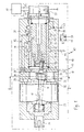
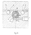
- the electrohydraulic designated 10 in FIG. 1 Drive unit includes as a power drive a rotary hydromotor designed as a gerotor 11 as well as an electrohydraulic designated overall by 12 Control device with the hydraulic motor 11 combined into a compact unit 13 is.
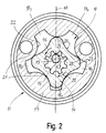
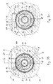
- the gerotor motor 11, for its explanation also on 2 is one of the basic form according to star-shaped rotor 14, which with respect to a central Rotor axis 16 in multiple, in the illustrated, special embodiment four-fold rotationally symmetrical and a rotor 16 surrounding it, annular stator 17, which is the basic shape of a ring gear with an internal toothing that is the radially outer Limitation of a stator interior accommodating the rotor 14 18 forms, which in turn with respect to central longitudinal axis 19 of the motor 11 and the drive unit 10 is designed to be rotationally symmetrical overall, where the multiplicity of the stator symmetry is 1 higher is that of the rotor 14 and in the illustrated special embodiment is thus 5-digit.
- the radially inwardly projecting teeth 21 of the stator 17th are as extending parallel to the central longitudinal axis 19 convex ribs with circular arches Shell surfaces 22 are formed.
- the prongs 23, i.e. the most radially protruding Areas of the star-shaped rotor 14 are with a Radius of curvature that is smaller than that Ribs 21 of the stator 17, convexly curved and close with smooth curvature on flat concave, between the jacket regions 24 of the rotor imparting the prongs 23 14 whose radius of curvature is larger than that the lateral surfaces 22 of the ribs 21 of the stator 17th
- the rotor 14 and the stator 17 of the gerotor 11 have the same axial thickness and are arranged between annular disks 26 and 27 of the motor housing, designated overall by 28, which form the housing-fixed, axial boundaries of the five drive chambers 18 1 to 18 5 of the gerotor 11, which radially on the outside fixed to the housing by the stator 17 and radially on the inside by the rotor 14, whose alternating convex and concave shell contour profile is matched to that of the stator 17 in such a way that the rotor 14 in all possible azimuthal positions with respect to its central axis 16 containing reference plane, the orientation of which can be selected at will, is in contact with each of the toothed ribs 21 of the stator along a generatrix 29 which run parallel to the central longitudinal axes 16 and 19 of the rotor 14 and the stator 17, two in each along these lines of contact 29 Seen circumferentially adjacent A drive chambers are tightly delimited from each other.
- the rotor 14 can be driven to perform rotations about its central axis 16, which in this case, when the rotor 14 rotates in the clockwise direction represented by the front part 31, counterclockwise rotary movements about the central axis 19 of the stator, the number of revolutions of the central axis 16 of the rotor around the central axis 19 of the stator 14 compared to the number of revolutions of the rotor 14 about its central axis 16 about the multiplicity of the rotor symmetry, at Special embodiment shown is therefore four times higher than the number of revolutions of the rotor about its central axis 16.
- the rotary slide valve 32 the piston 33 of which is rotationally coupled to the rotor 14 of the gerotor 11 via an articulated shaft 34, through which the superimposed ones , epicycloidal movements of the rotor 14 of the gerotor 11, namely the rotation of the rotor 14 about its central longitudinal axis 16 and its epicycloidal movement about the central longitudinal axis 19 of the stator 17 of the gerotor 11, in a uniaxial rotational movement of the valve piston 33 of the rotary slide valve 32 around the e.g. Entral longitudinal axis 19 of the drive unit 10 are implemented.
- the direction of rotation of the rotor 14 is determined by through which of its control connections 37 or 38 under Hydraulic medium under pressure to the gerotor motor 11 is supplied and to the unpressurized reservoir of the Pressure supply unit can flow out, the Speed of the rotor 14 through the setting - control - The amount of the gerotor 11 in the time unit flowing hydraulic medium is controlled.
- electro-hydraulic control device 12 mediates that as a position control loop for positioning of the rotor 14 of the gerotor motor 11 and with electrically controllable position setpoint specification and mechanical actual position feedback is working.
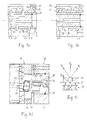
- the electrohydraulic control device comprises a total flow control valve designated 39 that the function of a 4/3-way proportional valve mediates that by controlling an electrical Stepper motor 41 in alternative directions of rotation in alternative Functional positions I (Fig. 1) and II (Fig. 1a) is controllable, which in turn alternative directions of rotation of the gerotor motor 11 correspond.
- Functional position I of the follow-up control valve 39 are its high pressure (P) supply port 42 to the A control port 37 of the gerotor motor 11 and its B control connection 38 with the unpressurized tank (T) supply connection 43 of the follow-up control valve 39 connected, which is an operating state of the gerotor motor 11 may correspond in which the rotor 14, seen in the direction of arrow 44 of Fig. 1, i.e. from the stepper motor 41 in the direction of the central longitudinal axis 19 of the gerotor motor 11 in the arrow 31 of the Fig. 2 represents clockwise rotation.
- the stepper motor 41 becomes in the opposite direction of rotation driven, the overrun control valve arrives 39 in its alternative function position to the first mentioned II (Fig. 1a), in which the B control connection 38 of the gerotor motor 11 with the P supply connection 42 of the follow-up control valve 39 and its A control connection 37 with the T supply connection 43 of the follow-up control valve are connected and thereby the gerotor motor 11, seen in the illustration of FIG. 2, for Execution of rotary movements in the direction of the arrow 46, i.e. is driven counterclockwise.
- the overrun control valve 39 is, according to it Function as a 4/3-way valve, designed so that when always the overflow control valve from one of its two alternative function positions I and II, the drive functions of the gerotor motor 11 in alternative directions of rotation are assigned in the other direction of rotation assigned function position is switched, this switchover via an intermediate position 0 (Fig. 1b) leads in which both the A control connection 37 and also the B control connection 38 of the gerotor motor 11 against the P supply port 42 and the T supply port 43 of the follow-up control valve 39 shut off are.
- the overrun control valve 39 is designed, in accordance with its function as a proportional valve, in such a way that between control positions ⁇ 1 and ⁇ 3 (FIG. 1c) the respective maximum flow cross section Q max of the flow paths of the wake released in the functional positions I and II Control valve, and the blocking position 0, which corresponds to the intermediate position ⁇ 2 , the flow cross-sections of these flow paths 47 and 48 or 49 and 51 vary monotonically between the maximum value Q max and the value 0.
- the follow-up control valve 39 is on the output shaft 36 of the gerotor motor 11 facing away from the same mounted on its housing 28. It includes one with the Housing 28 of the gerotor motor 11 firmly connected housing 52, the one continuous, central, with the central Longitudinal axis 19 of the gerotor motor 11 coaxial Bore 53 has, in, against the housing bore 53 sealed, a cylindrical-tubular valve bushing 54 is rotatably arranged by means of the stepper motor 41 can be driven in rotation, which in turn - Stator-proof - to the housing 52 of the overrun control valve is mounted.
- valve piston 57 In the through central bore 56 of the valve sleeve 54, sealed against this, is one of the basic form after cylindrical valve piston 57 around the central Axis 19 of the gerotor 11 rotatably arranged, the Valve piston 37 by means of a - play-free - overall with 58 designated feedback gear with the rotor 14 of the gerotor motor 11 rotationally coupled in motion is.
- the drive unit 10 for positioning a Workpiece or a machine element used its drive coupling with the gerotor motor 11 by a - not shown - rack drive can be realized, the one with the to be positioned Element firmly connected rack and one with this meshing, with the output shaft 36 of the gerotor motor 11 rotatably connected pinion includes, taking into account the gear ratios this rack and pinion drive and the feedback gear at every moment of operation of the drive unit 10 the position setpoint by the algebraic sum of the up to this moment the stepper motor 41 from an electronic one Control unit 59 supplied step control pulses given by which the stepper motor 51 and thus the gerotor motor 11 in alternative directions of rotation can be controlled, provided that that the stepper motor rotor by each of these drive pulses to perform an incremental rotation driven by the same angular amount ⁇ is and which for controlling the stepper motor 41 in output pulses used in the opposite direction of rotation the electronic control unit 59 which the Stepper motor at various control inputs 61 and 62 be forwarded with the opposite sign "counte
- the drive unit 10 acts as a rotary drive for a rotary during machining driven workpiece or machine element used, that directly or via a gearbox with the rotary Output shaft 36 of the gerotor motor 11 of the drive is coupled, it depends essentially on the rotational speed arrives, so is that Speed setpoint essentially, i.e. in turn apart from gear ratio, determined by the frequency with which the drive pulses for the stepper motor 41 from the electronic control unit 59 are issued.
- the maximum permissible - azimuthal - follow-up error ⁇ max which can still be used to achieve a good response of the control device 12, has a typical amount of 20 °, which is 2/3 of the maximum possible control angle of the follow-up Control valve 39 corresponds.
- a ring gear 63 which is in coaxial Arrangement with the common central longitudinal axis 19 of the gerotor motor 11 and the overrun control valve 12 rotatably connected to the central valve piston 57 and on the side facing the gerotor motor 11 is arranged, and a rotationally fixed to the rotor 14 of the Gerotor motor 11 connected pinion 64, which with its External teeth 66 in meshing engagement with the internal teeth 67 of the ring gear 63 stands and with respect to the central, rotor-fixed longitudinal axis 16 of the same coaxial and therefore with respect to the common central longitudinal axis 19 of the gerotor motor 11 and the follow-up control valve is arranged off-axis.
- the number of teeth z1 of the pinion is significantly smaller than the number of teeth z2 of the internal toothing 67 of the ring gear 63 and corresponds to about half their value.
- the number of teeth z1 of the pinion is 16 and the number of teeth z2 of the hoist wheel 63 has the value 30.
- Feedback gear 58 is the operating state of the gerotor motor 11, in which the rotor 14 itself, viewed in the direction of arrow 44 of FIG. 1, in Clockwise, i.e. in the direction of arrow 31 of FIG. 2, turns.
- the central longitudinal axis 16 of the rotor 14 below the central longitudinal axis 19 of the stator 17 of the gerotor motor 11 runs and the volume of the deepest drive chamber 18 1 corresponds to a minimum value
- the central longitudinal axis 16 of the rotor 14 whenever it rotates 90 ° clockwise describes a complete circular path around the central longitudinal axis 19 of the stator 17 of the gerotor in the counterclockwise direction.
- the pinion 64 thus, while undergoing a 360 ° clockwise rotation, makes four counterclockwise rotations about the central longitudinal axis 19 of the stator 17 of the gerotor motor 11, with the general rule that if the rotor 14 has N-fold symmetry, the latter central longitudinal axis N orbits around the central longitudinal axis 19 of the stator 17, while the rotor 14 undergoes a 360 ° rotation.
- valve bushing 54 of the follow-up control valve 39 In order to control a clockwise rotation of the output shaft 36 of the gerotor motor 11, the valve bushing 54 of the follow-up control valve 39 must be driven counterclockwise by means of the stepping motor 41 and at an angular speed that is 1/3 higher than the desired speed of rotation Output shaft 36.
- the embodiment according to FIG. 1d differs from that described with reference to FIG. 1 with regard to the design of the feedback transmission 58 'in that the ring gear 63' on the rotor 14 of the gerotor motor 11 and the pinion 64 'on the central valve piston 57 of the wake Control valve 39 are arranged, which are otherwise provided with the same design with regard to their number of teeth z 1 and z 2 .
- the feedback gear 58 ' according to FIG. 1d, under the same operating conditions as provided for the explanation of the gear 58 according to FIG. 1, results in a rotational drive of the central valve piston 57 in the same direction as the direction of rotation of the rotor 14 of the gerotor motor 11, the total transmission ratio I g 'through the relationship I.
- G ' N (e.g. 2nd / z 1 - 1) + z 2nd / z 1 is given, in which N again denotes the multiplicity of the rotational symmetry of the rotor 14 of the gerotor motor 11, z 1 the number of teeth of the pinion 64 'and z 2 the number of teeth of the internal toothing of the ring gear 63'.
- this transmission ratio I ' g the same dimensioning of the ring gear 63' and the pinion 64 ', as assumed for the exemplary embodiment according to FIG. 1, has the value 5.375.
- a functionally the feedback transmission 58 according to FIG. 1 corresponding feedback gearbox can also be implemented, that the ring gear is driven by a motor internally toothed end portion of the valve sleeve 54 is formed is and instead of this the central valve piston 57 can be driven by means of the stepping motor 41.
- the housing 52 of the follow-up control valve 39 is provided with a total of four annular grooves 71 to 74 which are open towards its central bore 53 and with which radially outer, flat annular grooves 76 to 79 of the essentially tubular valve bushing 54 are in constantly communicating connection.
- annular grooves 71 to 74 of the housing 52 of the follow-up control valve 39 and the annular grooves 76 to 79 of the valve bushing 54 of the follow-up control valve communicating with them are arranged at the same distance from one another, seen along the central longitudinal axis 19 thereof, the Motor 11 closest inner groove 71 of the follow-up control valve housing 52 and the inner groove 74 of the follow-up control valve housing 52 which is farthest away from the gerotor motor 11, each individually, communicating with one of the supply connections 42 and 43 of the follow-up control valve 39 are connected, as can also be seen from the schematic illustration in FIG. 1.
- the P-supply groove 71 of the follower control valve housing 52 adjacent inner groove 72 of the same is at illustrated embodiment over a total with 81 designated connection channel (Fig. 1) of the valve housing 52 with the A control connection 37 of the gerotor motor 11 connected.
- the T-supply groove 74 of the Housing 52 of the follow-up control valve 39 adjacent Inner groove 73 of its housing 52 is a total designated 82 connection port of the valve housing 52 of the follow-up control valve 39 with the B control connection 38 of the gerotor motor 11 communicatively connected, as the schematic representation of FIG. 1 can be seen.
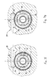
- the central valve piston 57 has one with the P supply groove 71 and the radially outer P-ring groove 76 the valve bushing 54 is provided with a coaxial P circumferential groove, the radial transverse bores 84 of the valve bushing 54 with their P-ring groove 76 and thus also with the P-supply groove 71 of the housing 52 in constant communication Connection is established.
- the central valve piston 57 has a with the T supply groove 74 of the housing as well as the radial outer T-ring groove 79 of the valve bushing 54 coaxial T-circumferential groove 86, which in turn via radial Cross bores 87 of the valve bush 54 with its T-ring groove 79 and thus also with the T supply groove 74 of the Housing 52 in constantly communicating connection stands (Fig. 3b).
- T circumferential groove 86 of the central valve body 57 two diametrically opposed, extends in the longitudinal direction to the P-circumferential groove 83 of the central valve body 57 extending T-control grooves 91 and 92, which are at an axial distance of the P-circumferential groove 83 of the central valve body 57 ends, the axial extension of these T-control grooves 91 and 92 is in turn chosen so that in axial Direction of overlap of these T control grooves 91 and 92 with the A-ring groove 77 of the valve bushing 54 and thus also with the A-ring groove 71 of the valve housing 52.
- the common longitudinal median plane 93 of the P control grooves 88 and 89 and the common longitudinal median plane 94 of the T control grooves 91 and 92 of the central valve piston 57 extend perpendicular to each other and cut along the central longitudinal axis 19 of the follow-up control valve 39.
- P control grooves 88 and 89 and T control grooves 91 and 92 have, in the circumferential direction of the central valve piston 57 seen, the same azimuthal width ⁇ of 40 °.
- the valve bushing 54 is provided with two, their sheath radially penetrating A-control channels 96 and 97 provided, the radially outside in the with the A-ring groove 72 of the housing 52 in constantly communicating Connected A-ring groove 77 of the valve bushing 54 mouth.
- a control channels 96 and 97 are each radial Hole 98 with a circular cross section and from this outgoing, circumferential expansion slots 99 and 101 formed, their in axial Direction measured inside width is smaller than that Diameter of the central radial bore 98, and their azimuthal depth measured in the circumferential direction so is dimensioned so that the circumference of the central valve piston 57 measured azimuthal width ⁇ of these A control channels 96 and 97 the azimuthal distance of the P control grooves 88 and 89 corresponds to T-tax slots 91 and 92, i.e. in the exemplary embodiment chosen for explanation has the value of 50 °.
- valve bushing 54 is with two, yours Training according to the A control channels 96 and 97 corresponding, radially penetrating the jacket of the valve bushing 94 B control channels (Fig. 3c) provided the radial outside with the B-ring groove 72 of the housing 52 B-ring groove in constant communication 78 of the valve bush 54 open.
- the common central longitudinal axis 104 of the B control channels 102 and 103 of the valve bushing 54 is opposite the common central longitudinal axis 106 of the A control channels 96 and 97 (Fig. 3b) offset by 90 ° in the azimuthal direction.
- the A connection channel 81 of the follow-up control valve 39 is through a perpendicular to its central longitudinal axis 19 and at a radial distance from this transverse bore 107, which with the A-ring groove 72 of the housing 52nd of the follow-up control valve 39 in communicating connection stands, and one communicating with the transverse bore 107 Connected, radially outside the A-ring groove 72 of the housing 52 extending longitudinal bores 108 of the valve housing 52 formed with the A control port 37 of the gerotor motor 11 or its direction of rotation control valve 32 in communicating connection stands.
- the B connection channel 82 of the follow-up control valve is analogous 39 by a right angle to his central longitudinal axis 19 and at a radial distance from this extending transverse bores 109, which with the B-ring groove 73 of the housing 52 of the follow-up control valve 39 has a communicating connection, and one with the Transverse bore 109 communicating, radially outside of the B-ring groove 73 of the housing 52 extending longitudinal bore 111 of the valve housing 52 is formed, the one with the B control connection 38 of the gerotor motor 11 or of its direction of rotation control valve 32 in communicating connection.
- a section of the A-connection channel 81 and of the B-connecting channel 82 of the follow-up control valve Cross bores 107 and 109, for those from the outside of the valve housing 52 brought into this are plugged pressure-tight on these outer sides.
- This configuration of the follow-up control valve corresponds Equality of target and actual value of the azimuthal Position of the rotor 14 of the gerotor motor 11. You becomes - as it were inevitable - at the end of a positioning process reaches and therefore forms the Starting position for a subsequent positioning process, which always from the in Figs. 3b and 3c illustrated position of the follow-up control valve 39 starts out.
- La schematically shown functional position II arrives in the Rotor 14 of the gerotor 11 in the direction of rotation that the overrun control valve 39 in its functional position I mediated, driven opposite direction again, depending on how the feedback gearbox 58 or 58 'of the drive unit 10 designed is.
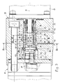
- a torsion spring mediating, generally designated 114 bracing device provided on the central valve piston 57 one on the valve bushing 54, which rotates with the output shaft of the stepper motor 41 is connected, exerts azimuthally supported torque due to whose the internal toothing 67 with the central valve piston 57 non-rotatably connected ring gear reliably in one-sided system with those in engagement with it Teeth of the pinion 64 is held rotatably connected to the rotor 14 of the gerotor motor is.
- This tensioning device 114 comprises a tensioned under tension standing coil spring 116 on a about 300 ° spanning azimuthal range of one outer, concave groove 117 one in the axial direction only a little extended, from the central housing bore 53 end section 118 projecting on the transmission side the valve bushing 54 is received.
- the radius of curvature the groove is slightly larger than the one of spring coils with a radially inner 180 ° range taken up by this concave groove 117 and are supported at the bottom.
- the short end section 118 of the valve bushing 54 penetrates one over the central bore 53 in which the valve bushing on sections their length arranged in a pressure-tight, rotatable manner is, advanced hole level 119, its diameter is slightly larger than the outside diameter the coil spring 116, the radial internal width of the between bore step 119 and the outer surface of the end section carrying the coil spring 116 118 of the valve bushing 54 remaining annular gap 121 is smaller than the diameter of the individual spring coils, with a spring wire thickness of 0.2 mm approx. Is 2 mm. As a result, the coil spring 116 is against sufficient axial disengagement from the annular gap 121 secured.
- This stop pin 122 is oriented so that the its central longitudinal axis 126 and the central longitudinal axis 19 of the trailing control valve 39 containing radial plane halves the angle that the radial plane, which is the common central longitudinal axis 106 of the A control channels 96 and 97 contains and the radial plane, which is the common central longitudinal axis 104 of the B control channels 102 and 103 includes.
- One end 127 of the coil spring 116 is on the free End portion 122 'of the stop pin 122 attached, while the other end 128 at the in the direction the spring seen about 300 ° distant area of the 300 ° sector-shaped jacket section 118 of the valve bushing 54 is set.
- the helical spring 116 is dimensioned and their preload on the holding torque of the Stepper motor 41 in its de-energized state and that Holding torque of the gerotor motor 11 when switched off Pressure supply adjusted so that the between the valve sleeve 54 and the central valve piston 57 - as a result between the stepper motor rotor 41 and the rotor 14 of the gerotor motor - due the spring preload permanently effective torque far from sufficient, this in a standstill phase to rotate the drive unit against each other.
- the Overrun control valve 39 can therefore be used after the gerotor motor 11 is stopped and it is in its locking middle position has not achieved, as it were, in reach.
- Preload of the coil spring 116 of the bracing device 114 is only sufficient to ensure that for the exact feedback of the actual position of the Rotor 14 of the gerotor motor 11 required clearance of the respective feedback gear 58 or 58 ' is guaranteed.
Landscapes
- Engineering & Computer Science (AREA)
- Mechanical Engineering (AREA)
- General Engineering & Computer Science (AREA)
- Hydraulic Motors (AREA)
- Rotary Pumps (AREA)
- Valve Device For Special Equipments (AREA)
- Fluid-Pressure Circuits (AREA)
- Jib Cranes (AREA)
- Servomotors (AREA)
- Connection Of Motors, Electrical Generators, Mechanical Devices, And The Like (AREA)
- Control Of Stepping Motors (AREA)
Applications Claiming Priority (3)
| Application Number | Priority Date | Filing Date | Title |
|---|---|---|---|
| DE19522768 | 1995-06-27 | ||
| DE19522768A DE19522768A1 (de) | 1995-06-27 | 1995-06-27 | Elektrohydraulische Steuerungseinrichtung für einen Rotations-Hydromotor |
| PCT/EP1996/002818 WO1997001711A1 (de) | 1995-06-27 | 1996-06-27 | Elektrohydraulische steuerungseinrichtung für einen rotations-hydromotor |
Publications (2)
| Publication Number | Publication Date |
|---|---|
| EP0835382A1 EP0835382A1 (de) | 1998-04-15 |
| EP0835382B1 true EP0835382B1 (de) | 1999-03-24 |
Family
ID=7765046
Family Applications (1)
| Application Number | Title | Priority Date | Filing Date |
|---|---|---|---|
| EP96923960A Expired - Lifetime EP0835382B1 (de) | 1995-06-27 | 1996-06-27 | Rotations-hydromotor mit elektrohydraulischer steuerungseinrichtung |
Country Status (5)
| Country | Link |
|---|---|
| EP (1) | EP0835382B1 (da) |
| AT (1) | ATE178123T1 (da) |
| DE (2) | DE19522768A1 (da) |
| DK (1) | DK0835382T3 (da) |
| WO (1) | WO1997001711A1 (da) |
Families Citing this family (5)
| Publication number | Priority date | Publication date | Assignee | Title |
|---|---|---|---|---|
| DE19945122B4 (de) * | 1999-09-21 | 2004-08-12 | Sauer-Danfoss Holding Aps | Hydraulische Steuereinrichtung |
| US6439101B1 (en) * | 1999-10-13 | 2002-08-27 | Teijin Seiki Co., Ltd. | Electro-hydraulic servomotor |
| CN104847258B (zh) * | 2015-04-20 | 2017-12-08 | 江汉石油钻头股份有限公司 | 一种全金属螺杆钻具 |
| CN104847257B (zh) * | 2015-04-20 | 2017-12-08 | 江汉石油钻头股份有限公司 | 一种螺杆钻具马达 |
| CN117552922B (zh) * | 2024-01-11 | 2024-03-22 | 宁波中意液压马达有限公司 | 一种节能型液压摆线马达 |
Family Cites Families (4)
| Publication number | Priority date | Publication date | Assignee | Title |
|---|---|---|---|---|
| DE2110863B1 (de) * | 1971-03-08 | 1972-08-31 | Danfoss As | Parallel- und innenachsige Rotationskolbenmaschine |
| US4494915A (en) * | 1979-06-25 | 1985-01-22 | White Hollis Newcomb Jun | Hydrostatic steering unit with cylindrical slide member within clindrical valve sleeve |
| DE4015101A1 (de) * | 1990-05-11 | 1991-11-14 | Eckehart Schulze | Hydraulische antriebsvorrichtung |
| DE9308025U1 (de) * | 1993-05-27 | 1993-07-29 | Moog GmbH, 7030 Böblingen | Hydromotor |
-
1995
- 1995-06-27 DE DE19522768A patent/DE19522768A1/de not_active Withdrawn
-
1996
- 1996-06-27 AT AT96923960T patent/ATE178123T1/de not_active IP Right Cessation
- 1996-06-27 WO PCT/EP1996/002818 patent/WO1997001711A1/de not_active Ceased
- 1996-06-27 DK DK96923960T patent/DK0835382T3/da active
- 1996-06-27 EP EP96923960A patent/EP0835382B1/de not_active Expired - Lifetime
- 1996-06-27 DE DE59601508T patent/DE59601508D1/de not_active Expired - Fee Related
Also Published As
| Publication number | Publication date |
|---|---|
| EP0835382A1 (de) | 1998-04-15 |
| DE59601508D1 (de) | 1999-04-29 |
| DE19522768A1 (de) | 1997-01-02 |
| DK0835382T3 (da) | 2000-06-05 |
| ATE178123T1 (de) | 1999-04-15 |
| WO1997001711A1 (de) | 1997-01-16 |
Similar Documents
| Publication | Publication Date | Title |
|---|---|---|
| DE3810804C2 (da) | ||
| EP0918961B1 (de) | Untersetzungsgetriebe | |
| EP0981696B1 (de) | Exzenterzahnradgetriebe | |
| DE3938353C2 (de) | Spindelantriebsvorrichtung zur Erzeugung von wahlweisen Linear- und/oder Drehbewegungen der Spindel | |
| EP1347154B1 (de) | Ventilsteuerung zur Einstellung des Hubes von Ventilen in einer Brennkraftmaschine | |
| DE1805818C3 (de) | Rotationskolbenmotor | |
| DE10110282A1 (de) | Planetengetriebe | |
| DE4446950C2 (de) | Schrittantrieb | |
| EP0835382B1 (de) | Rotations-hydromotor mit elektrohydraulischer steuerungseinrichtung | |
| DE102006035391A1 (de) | Rotationslinearstellglied, Linearbewegungswellenmechanismus, variabler Ventilbetätigungsmechanismus und Motor mit variablem Ventil | |
| DE1948392B2 (de) | Verteilerdrehventil für eine als Pumpe oder Motor verwendbare hydraulische Rotationskolbenmaschine | |
| EP2616644B1 (de) | Vorrichtung zur phasenverschiebung des drehwinkels eines antriebsrades zu einem abtriebsrad | |
| DE4022735A1 (de) | Spielfreie phaseneinstellvorrichtung | |
| DE69821433T2 (de) | Leistungsgetriebe für Drehbewegungsübertragung | |
| DE1906445B2 (de) | Steuerdrehschiebereinrichtung an einer Rotationskolbenmaschine | |
| EP0141874A1 (de) | Wegeventilvorrichtung | |
| DE102005030650A1 (de) | Aktuator für eine Ventilhubsteuervorrichtung mit einem Nockenmechanismus | |
| EP1853796B1 (de) | Verstellvorrichtung für variable ventilsteuerung | |
| DE3224951C2 (da) | ||
| EP0167697B1 (de) | Einspritzzeitpunktversteller einer Einspritzpumpe für Brennkraftmaschinen | |
| DE1259163B (de) | Durch Drehbewegungen betaetigtes Steuerventil | |
| DE1503366C3 (de) | Drehkolben-Flüssigkeitsmaschine | |
| DE102004022362B4 (de) | Schaltbare mehrstufige Ölpumpe | |
| DE2451325C3 (de) | Parallel- und außenachsige Rotationskolbenmaschine | |
| DE2532928A1 (de) | Elektrohydraulischer impulsmotor mit drehfuehrungsventilmitteln |
Legal Events
| Date | Code | Title | Description |
|---|---|---|---|
| PUAI | Public reference made under article 153(3) epc to a published international application that has entered the european phase |
Free format text: ORIGINAL CODE: 0009012 |
|
| 17P | Request for examination filed |
Effective date: 19970807 |
|
| AK | Designated contracting states |
Kind code of ref document: A1 Designated state(s): AT DE DK GB IT |
|
| GRAG | Despatch of communication of intention to grant |
Free format text: ORIGINAL CODE: EPIDOS AGRA |
|
| 17Q | First examination report despatched |
Effective date: 19980608 |
|
| GRAG | Despatch of communication of intention to grant |
Free format text: ORIGINAL CODE: EPIDOS AGRA |
|
| GRAH | Despatch of communication of intention to grant a patent |
Free format text: ORIGINAL CODE: EPIDOS IGRA |
|
| GRAH | Despatch of communication of intention to grant a patent |
Free format text: ORIGINAL CODE: EPIDOS IGRA |
|
| GRAA | (expected) grant |
Free format text: ORIGINAL CODE: 0009210 |
|
| AK | Designated contracting states |
Kind code of ref document: B1 Designated state(s): AT DE DK GB IT |
|
| REF | Corresponds to: |
Ref document number: 178123 Country of ref document: AT Date of ref document: 19990415 Kind code of ref document: T |
|
| REF | Corresponds to: |
Ref document number: 59601508 Country of ref document: DE Date of ref document: 19990429 |
|
| GBT | Gb: translation of ep patent filed (gb section 77(6)(a)/1977) |
Effective date: 19990427 |
|
| PLBE | No opposition filed within time limit |
Free format text: ORIGINAL CODE: 0009261 |
|
| STAA | Information on the status of an ep patent application or granted ep patent |
Free format text: STATUS: NO OPPOSITION FILED WITHIN TIME LIMIT |
|
| 26N | No opposition filed | ||
| PGFP | Annual fee paid to national office [announced via postgrant information from national office to epo] |
Ref country code: DK Payment date: 20000512 Year of fee payment: 5 |
|
| REG | Reference to a national code |
Ref country code: DK Ref legal event code: T3 |
|
| PG25 | Lapsed in a contracting state [announced via postgrant information from national office to epo] |
Ref country code: DK Free format text: LAPSE BECAUSE OF NON-PAYMENT OF DUE FEES Effective date: 20010627 |
|
| REG | Reference to a national code |
Ref country code: GB Ref legal event code: IF02 |
|
| REG | Reference to a national code |
Ref country code: DK Ref legal event code: EBP |
|
| REG | Reference to a national code |
Ref country code: GB Ref legal event code: 732E |
|
| PGFP | Annual fee paid to national office [announced via postgrant information from national office to epo] |
Ref country code: AT Payment date: 20030508 Year of fee payment: 8 |
|
| PG25 | Lapsed in a contracting state [announced via postgrant information from national office to epo] |
Ref country code: AT Free format text: LAPSE BECAUSE OF NON-PAYMENT OF DUE FEES Effective date: 20040627 |
|
| PGFP | Annual fee paid to national office [announced via postgrant information from national office to epo] |
Ref country code: GB Payment date: 20040712 Year of fee payment: 9 |
|
| PGFP | Annual fee paid to national office [announced via postgrant information from national office to epo] |
Ref country code: DE Payment date: 20050623 Year of fee payment: 10 |
|
| PG25 | Lapsed in a contracting state [announced via postgrant information from national office to epo] |
Ref country code: IT Free format text: LAPSE BECAUSE OF NON-PAYMENT OF DUE FEES Effective date: 20050627 Ref country code: GB Free format text: LAPSE BECAUSE OF NON-PAYMENT OF DUE FEES Effective date: 20050627 |
|
| GBPC | Gb: european patent ceased through non-payment of renewal fee |
Effective date: 20050627 |
|
| PG25 | Lapsed in a contracting state [announced via postgrant information from national office to epo] |
Ref country code: DE Free format text: LAPSE BECAUSE OF NON-PAYMENT OF DUE FEES Effective date: 20070103 |