EP0833780B1 - Verfahren zur herstellung eines rohrkörpers und verfahren zur herstellung einer tube unter verwendung des rohrkörpers - Google Patents
Verfahren zur herstellung eines rohrkörpers und verfahren zur herstellung einer tube unter verwendung des rohrkörpers Download PDFInfo
- Publication number
- EP0833780B1 EP0833780B1 EP96920829A EP96920829A EP0833780B1 EP 0833780 B1 EP0833780 B1 EP 0833780B1 EP 96920829 A EP96920829 A EP 96920829A EP 96920829 A EP96920829 A EP 96920829A EP 0833780 B1 EP0833780 B1 EP 0833780B1
- Authority
- EP
- European Patent Office
- Prior art keywords
- partition wall
- strip
- foil strip
- process according
- tube
- Prior art date
- Legal status (The legal status is an assumption and is not a legal conclusion. Google has not performed a legal analysis and makes no representation as to the accuracy of the status listed.)
- Expired - Lifetime
Links
Images


Classifications
-
- B—PERFORMING OPERATIONS; TRANSPORTING
- B65—CONVEYING; PACKING; STORING; HANDLING THIN OR FILAMENTARY MATERIAL
- B65D—CONTAINERS FOR STORAGE OR TRANSPORT OF ARTICLES OR MATERIALS, e.g. BAGS, BARRELS, BOTTLES, BOXES, CANS, CARTONS, CRATES, DRUMS, JARS, TANKS, HOPPERS, FORWARDING CONTAINERS; ACCESSORIES, CLOSURES, OR FITTINGS THEREFOR; PACKAGING ELEMENTS; PACKAGES
- B65D35/00—Pliable tubular containers adapted to be permanently or temporarily deformed to expel contents, e.g. collapsible tubes for toothpaste or other plastic or semi-liquid material; Holders therefor
- B65D35/22—Pliable tubular containers adapted to be permanently or temporarily deformed to expel contents, e.g. collapsible tubes for toothpaste or other plastic or semi-liquid material; Holders therefor with two or more compartments
-
- B—PERFORMING OPERATIONS; TRANSPORTING
- B29—WORKING OF PLASTICS; WORKING OF SUBSTANCES IN A PLASTIC STATE IN GENERAL
- B29D—PRODUCING PARTICULAR ARTICLES FROM PLASTICS OR FROM SUBSTANCES IN A PLASTIC STATE
- B29D23/00—Producing tubular articles
- B29D23/001—Pipes; Pipe joints
-
- B—PERFORMING OPERATIONS; TRANSPORTING
- B29—WORKING OF PLASTICS; WORKING OF SUBSTANCES IN A PLASTIC STATE IN GENERAL
- B29D—PRODUCING PARTICULAR ARTICLES FROM PLASTICS OR FROM SUBSTANCES IN A PLASTIC STATE
- B29D23/00—Producing tubular articles
- B29D23/20—Flexible squeeze tubes, e.g. for cosmetics
-
- B—PERFORMING OPERATIONS; TRANSPORTING
- B29—WORKING OF PLASTICS; WORKING OF SUBSTANCES IN A PLASTIC STATE IN GENERAL
- B29C—SHAPING OR JOINING OF PLASTICS; SHAPING OF MATERIAL IN A PLASTIC STATE, NOT OTHERWISE PROVIDED FOR; AFTER-TREATMENT OF THE SHAPED PRODUCTS, e.g. REPAIRING
- B29C53/00—Shaping by bending, folding, twisting, straightening or flattening; Apparatus therefor
- B29C53/36—Bending and joining, e.g. for making hollow articles
- B29C53/38—Bending and joining, e.g. for making hollow articles by bending sheets or strips at right angles to the longitudinal axis of the article being formed and joining the edges
- B29C53/40—Bending and joining, e.g. for making hollow articles by bending sheets or strips at right angles to the longitudinal axis of the article being formed and joining the edges for articles of definite length, i.e. discrete articles
-
- B—PERFORMING OPERATIONS; TRANSPORTING
- B29—WORKING OF PLASTICS; WORKING OF SUBSTANCES IN A PLASTIC STATE IN GENERAL
- B29C—SHAPING OR JOINING OF PLASTICS; SHAPING OF MATERIAL IN A PLASTIC STATE, NOT OTHERWISE PROVIDED FOR; AFTER-TREATMENT OF THE SHAPED PRODUCTS, e.g. REPAIRING
- B29C53/00—Shaping by bending, folding, twisting, straightening or flattening; Apparatus therefor
- B29C53/36—Bending and joining, e.g. for making hollow articles
- B29C53/38—Bending and joining, e.g. for making hollow articles by bending sheets or strips at right angles to the longitudinal axis of the article being formed and joining the edges
- B29C53/48—Bending and joining, e.g. for making hollow articles by bending sheets or strips at right angles to the longitudinal axis of the article being formed and joining the edges for articles of indefinite length, i.e. bending a strip progressively
-
- B—PERFORMING OPERATIONS; TRANSPORTING
- B29—WORKING OF PLASTICS; WORKING OF SUBSTANCES IN A PLASTIC STATE IN GENERAL
- B29L—INDEXING SCHEME ASSOCIATED WITH SUBCLASS B29C, RELATING TO PARTICULAR ARTICLES
- B29L2031/00—Other particular articles
- B29L2031/60—Multitubular or multicompartmented articles, e.g. honeycomb
- B29L2031/601—Multi-tubular articles, i.e. composed of a plurality of tubes
-
- Y—GENERAL TAGGING OF NEW TECHNOLOGICAL DEVELOPMENTS; GENERAL TAGGING OF CROSS-SECTIONAL TECHNOLOGIES SPANNING OVER SEVERAL SECTIONS OF THE IPC; TECHNICAL SUBJECTS COVERED BY FORMER USPC CROSS-REFERENCE ART COLLECTIONS [XRACs] AND DIGESTS
- Y10—TECHNICAL SUBJECTS COVERED BY FORMER USPC
- Y10S—TECHNICAL SUBJECTS COVERED BY FORMER USPC CROSS-REFERENCE ART COLLECTIONS [XRACs] AND DIGESTS
- Y10S493/00—Manufacturing container or tube from paper; or other manufacturing from a sheet or web
- Y10S493/916—Pliable container
- Y10S493/931—Pliable container having plural compartments
-
- Y—GENERAL TAGGING OF NEW TECHNOLOGICAL DEVELOPMENTS; GENERAL TAGGING OF CROSS-SECTIONAL TECHNOLOGIES SPANNING OVER SEVERAL SECTIONS OF THE IPC; TECHNICAL SUBJECTS COVERED BY FORMER USPC CROSS-REFERENCE ART COLLECTIONS [XRACs] AND DIGESTS
- Y10—TECHNICAL SUBJECTS COVERED BY FORMER USPC
- Y10T—TECHNICAL SUBJECTS COVERED BY FORMER US CLASSIFICATION
- Y10T156/00—Adhesive bonding and miscellaneous chemical manufacture
- Y10T156/10—Methods of surface bonding and/or assembly therefor
- Y10T156/1002—Methods of surface bonding and/or assembly therefor with permanent bending or reshaping or surface deformation of self sustaining lamina
- Y10T156/1007—Running or continuous length work
- Y10T156/1008—Longitudinal bending
- Y10T156/1013—Longitudinal bending and edge-joining of one piece blank to form tube
-
- Y—GENERAL TAGGING OF NEW TECHNOLOGICAL DEVELOPMENTS; GENERAL TAGGING OF CROSS-SECTIONAL TECHNOLOGIES SPANNING OVER SEVERAL SECTIONS OF THE IPC; TECHNICAL SUBJECTS COVERED BY FORMER USPC CROSS-REFERENCE ART COLLECTIONS [XRACs] AND DIGESTS
- Y10—TECHNICAL SUBJECTS COVERED BY FORMER USPC
- Y10T—TECHNICAL SUBJECTS COVERED BY FORMER US CLASSIFICATION
- Y10T156/00—Adhesive bonding and miscellaneous chemical manufacture
- Y10T156/10—Methods of surface bonding and/or assembly therefor
- Y10T156/1002—Methods of surface bonding and/or assembly therefor with permanent bending or reshaping or surface deformation of self sustaining lamina
- Y10T156/1036—Bending of one piece blank and joining edges to form article
- Y10T156/1038—Hollow cylinder article
Definitions
- the invention relates to a method for producing a in particular multilayer tubular body with at least one extending side by side along its length Partition forming longitudinal chambers using a Foil tape.
- DE-A1- 24 53 492 describes a generic method for the production a tubular body for a tube-like container is known, after which a multilayer thin sheet is so wound is made shaft-shaped and assembled that one piece the tubular wall, a central or tendon-shaped extending partition and extending in the circumferential direction extending overlapped longitudinal seams formed become.
- the circumferentially extending Overlap areas are sealed by heat or welded so that it extends longitudinally Form overlap joints or seams.
- the partition divides the space inside the tubular body into two longitudinally extending chambers lying side by side are arranged.
- the tubular body produced by the known methods are made with a prefabricated or molded tube head connected, which is also a separator for connection to the Has partition that extends into the dispensing opening. Above the dispensing opening is the dispensing opening overlapping closure which is in contact with the separator intended.
- a two-chamber tube is known from US-A-2 939 610, wherein two tubular bodies are arranged one inside the other.
- the provided cap has an inner cylindrical Projection on, in the closed state of the cap the tube head with the one below the upper edge of the Output opening ending separator communicates and the two Chambers also separated from each other in the tube head.
- the object of the invention is a method for the production an in particular multi-layer tubular body with at least one side by side along its length using dividing walls forming horizontal longitudinal chambers to specify a film tape that is quick and easy is feasible and also allows for any length of time Manufacture tubular body.
- the object of the invention is also a method for Production of tubes using the new Specify the method of manufacturing tubular bodies.
- the task is accomplished by a method of manufacturing a in particular multilayer tubular body with at least one extending side by side along its length Partition forming longitudinal chambers using a Foil tape solved, first on the foil tape or a cut-off film strip section a partition wall strip or a cut-off partition strip section in parallel Alignment with the film tape or film tape section with its outer edges and then the Side edges to form an endless tube, from which then Tubular body are cut to length, or directly of a tubular body be connected to each other.
- Claim 10 is an advantageous method for Production of a tube using the invention produced tubular body.
- Claims 11 to 14 contain advantageous developments of the method according to claim 10.
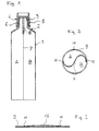
- the tube shown schematically in Fig. 1 has one Tubular body 1, which is firmly connected to a tube head 2 is.
- 1 is the Cap 4 designed as a screw cap 5 on a the external thread 6 surrounding the nozzle-shaped dispensing opening 3 can be screwed on.
- a partition 7 is in the tubular body 1 arranged, the tubular body 1 in two longitudinal chambers A and B. divided.
- the Tube head 2 in the exemplary embodiment according to FIG. 1 extending into the closing plane of the dispensing opening 3 Separator 8 on.
- the tubular body 1 can be made of any known one or Multi-layer material with or without a barrier layer from one Foil tape 9 by forming a seam 10 z. B. an overlap seam using the outer edges of the Foil tape 9 are produced.
- the tube head 2 can have one or more layers with or without Barrier layer to be made separately and with the tubular body 1, e.g. B. connected by welding. But he can also by directly molding plasticized Plastic material made on the prefabricated tubular body 1 become.
- the partition 7 can be made of the same material as that Tubular body 1 or from any other known and suitable material with or without a barrier layer.
- the partition 7 preferably consists of a material a thickness of 50 to 100 ⁇ , d. H. its strength is significantly less than that of the film for the tubular body 1, the usually between 300 and 500 microns.
- the partition 7 made of LDPE (Low Density Polyethylene) consist. It has been shown that the thinner the partition 7 is designed, the more even the joint output is from the two chambers A and B.
- the tube head 2 can, if an absolute separation of the Product components that are in the longitudinal chambers A and B should not be included before they are issued is required to be executed without a separator 8, so that there is a mixing chamber in the tube head.
- the Separator 8 at the contact point of the tube head 2 with the Tubular body 1 in cross section of the shape of the partition 7 correspond or be adapted.
- the top one End of the partition 7 on the partition 8 or vice versa attached that the longitudinal chambers A, B up to the through the Cap 4 closed delivery opening 3 from each other are separated.
- the lower end of the Partition 8 the upper end of the partition 7 (see FIG. 1).
- the lower end of the separating web 8, 8 ' can also over the Protrude basic level of the tube head 2, as this clearly can be seen in Fig. 8.
- the separating web 8 also divides the entire length of the discharge opening 3 in preferably two same parts.
- a variant can be, see e.g. B. the Closure cap 4 in Fig. 8, which as a hinged closure 12 hinged pivotable cover 13 is shown that the upper edge of the separating web 8 in the tube head 2 below the top of the discharge opening 3 ends.
- the cap 4 has a cross section of the Dispensing opening 3 corresponding, preferably cylindrical Parts having, projection 14 (Fig. 8) on the Closed position of the cap 4 close to the free The upper edge of the separating web 8 'abuts and the separation of the two longitudinal chambers A, B guaranteed.
- the protrusion also has another at the discharge opening 3 adapted shape as well as sealing edges and / or elastic elements exhibit.
- the hinged closure 12 can on the tube head 2 by means of a Snap connection (see Fig. 8), screw or by a fixed weld or adhesive connection.
- the free upper end of the separating web 8 a - preferably knife-like - projecting sealing edge 15.
- the sealing edge 15 can be resilient - in particular with twist locks - or also rigid - especially with Folding closures - be designed. If the sealant 15 is rigid, the projection 14 should Cap 4 preferably a resilient elastic Have counter surface in which the sealing edge 15 to Ensuring a practically absolute tightness somewhat can penetrate (see Fig. 9), with more flexible compliant Design of the projecting sealing edge 15 can be a kind Preload can be achieved, which then also tightness guaranteed if there is excess pressure in chambers A, B. prevails.
- the tubular body 1 for a tube with a partition 7 can be produced in a simple manner that on an endless film strip 9 (see FIGS. 2, 4 and 6) for Production of a known tube body continuously endless partition strips 16, 16 'in parallel alignment arranged to the film strip 9 and with its two outer as Fastening strips 11 serving edges (Fig. 2) or - once flat and once folded at the edge - as envelope fold 17 (Fig. 4) - is firmly connected to the film strip 9, for. B by welding or gluing. Will the partition strip 16 flat on one edge and overlapping on the other edge attached with envelope fold 17 to the film strip 9 (see FIG. 4) Partition side edges each tangent to the Tubular body wall (see Fig. 5). From the so produced In a second step, the raw material is then a pipe a known method z. B. by forming a Overlap seam made. Below are individual Separate the tube body of the desired length from the tube.
- a circular base (FIG. 3 and 7) or an oval (Fig. 5) cross-sectional shape become.
- the on the film strip 9 applied partition strips 16 ' parallel to the fastening strips 11 and thus also parallel to the longitudinal extent of the film strip 9 aligned crease 18.
- Fig. 7 allows a fold 18 - possibly two or several buckles, also facing each other (not shown) a predetermined orientation of the partition 7 within the tubular body 1, which by the arrangement of the Buckle 18 or the buckle in cross section of the Partition strip 16 'can be varied.
- folds advantageous because they are the same size or desired cross-sectional openings of any size Chambers A and B allow how to fill them required are.
- a preferred arrangement of a fold 18 in Partition strips 16 ' may consist in that Partition strips 16 'divided in a ratio of 1: 3 to 1: 5 becomes.
- one chamber or can optionally also have several chambers with one Blowing agents are filled, which is a lighter one hand Removing the filler and then on the other hand ensures a beautiful round appearance of the multi-chamber tube, when the filling material is almost empty.
Landscapes
- Engineering & Computer Science (AREA)
- Mechanical Engineering (AREA)
- Tubes (AREA)
- Shaping Of Tube Ends By Bending Or Straightening (AREA)
- Making Paper Articles (AREA)
- Rigid Pipes And Flexible Pipes (AREA)
- Laminated Bodies (AREA)
- Materials For Medical Uses (AREA)
- Closures For Containers (AREA)
- Perforating, Stamping-Out Or Severing By Means Other Than Cutting (AREA)
- Ceramic Products (AREA)
Applications Claiming Priority (3)
| Application Number | Priority Date | Filing Date | Title |
|---|---|---|---|
| DE19522169A DE19522169C2 (de) | 1995-06-19 | 1995-06-19 | Verfahren zur Herstellung eines insbesondere mehrschichtigen Rohrkörpers mit mindestens einer Trennwand für eine Tube |
| DE19522169 | 1995-06-19 | ||
| PCT/EP1996/002645 WO1997000208A1 (de) | 1995-06-19 | 1996-06-19 | Verfahren zur herstellung eines rohrkörpers und verfahren zur herstellung einer tube unter verwendung des rohrkörpers |
Publications (2)
| Publication Number | Publication Date |
|---|---|
| EP0833780A1 EP0833780A1 (de) | 1998-04-08 |
| EP0833780B1 true EP0833780B1 (de) | 2000-01-05 |
Family
ID=7764677
Family Applications (1)
| Application Number | Title | Priority Date | Filing Date |
|---|---|---|---|
| EP96920829A Expired - Lifetime EP0833780B1 (de) | 1995-06-19 | 1996-06-19 | Verfahren zur herstellung eines rohrkörpers und verfahren zur herstellung einer tube unter verwendung des rohrkörpers |
Country Status (17)
| Country | Link |
|---|---|
| US (1) | US5900086A (da) |
| EP (1) | EP0833780B1 (da) |
| JP (1) | JP3725551B2 (da) |
| KR (1) | KR100374621B1 (da) |
| CN (1) | CN1070142C (da) |
| AT (1) | ATE188434T1 (da) |
| AU (1) | AU709194B2 (da) |
| BG (1) | BG63111B1 (da) |
| BR (1) | BR9608931A (da) |
| DE (2) | DE19522169C2 (da) |
| DK (1) | DK0833780T3 (da) |
| ES (1) | ES2144249T3 (da) |
| GR (1) | GR3033068T3 (da) |
| HU (1) | HU226601B1 (da) |
| PL (1) | PL179114B1 (da) |
| RU (1) | RU2154005C2 (da) |
| WO (1) | WO1997000208A1 (da) |
Families Citing this family (27)
| Publication number | Priority date | Publication date | Assignee | Title |
|---|---|---|---|---|
| GB9619864D0 (en) * | 1996-09-24 | 1996-11-06 | Berol Limited | Coating fluids with reduced solvent evaporation |
| DE19640833C1 (de) * | 1996-10-02 | 1997-12-18 | Automation Industrielle Sa | Vorrichtung zur Herstellung von Zwei- oder Mehrkammertuben |
| US5782384A (en) * | 1996-11-05 | 1998-07-21 | Colgate-Palmolive | Aligned web in a container |
| EP0845422B1 (de) * | 1996-11-21 | 2000-03-29 | Aisa Automation Industrielle Sa | Verfahren zur Herstellung von Rohrkörpern |
| US5858153A (en) * | 1997-01-17 | 1999-01-12 | Colgate-Palmolive Company | Method for making tubular containers |
| DE19712736C1 (de) * | 1997-03-26 | 1998-11-12 | Maegerle Karl Lizenz | Verfahren zur Herstellung einer Mehrkammer-Verpackungstube |
| SE509412C2 (sv) * | 1997-05-27 | 1999-01-25 | Norden Pac Dev Ab | Anordning och förfarande i tubfyllningsmaskin |
| DE19747222C1 (de) * | 1997-10-25 | 1999-03-04 | Daimler Benz Ag | Verbrennungsmotoranlage mit Stickoxid-Speicherkatalysator und Betriebsverfahren hierfür |
| US6574946B1 (en) | 1997-12-05 | 2003-06-10 | Norden Pac Development Ab | Method and device for end closure of packaging tubes |
| DE19808649A1 (de) * | 1998-02-28 | 1999-09-02 | Iwk Verpackungstechnik Gmbh | Verfahren zum Befüllen einer Zwei-Kammer-Tube und Vorrichtung zu dessen Durchführung |
| CH693027A5 (de) * | 1998-05-07 | 2003-01-31 | Maegerle Karl Lizenz | Verfahren zur Herstellung einer Mehrkammer-Verpackungstube. |
| DE19900670C2 (de) * | 1999-01-11 | 2002-11-28 | Automation Industrielle Sa | Verfahren zur kontinuierlichen Herstellung von Tubenrohrkörpern |
| DE19911728C2 (de) * | 1999-03-16 | 2003-06-18 | Automation Industrielle Sa | Verfahren zur Herstellung einer Zweikammertube |
| CH695681A5 (de) * | 2000-08-22 | 2006-07-31 | Maegerle Karl Lizenz | Mehrkammertube |
| DE10057515C2 (de) * | 2000-11-21 | 2003-07-03 | Aisapack Holding Sa Vouvry | Verschlusskappe für Zweikammerbehälter |
| DE10237839B3 (de) * | 2002-08-19 | 2004-01-22 | Aisa Automation Industrielle S.A. | Anlage zum Herstellen und Verpacken von Tuben |
| SE525982C2 (sv) * | 2003-10-08 | 2005-06-07 | Tetra Laval Holdings & Finance | Förpackningsbehållare och metod att framställa en förpackningsbehållare |
| US7044333B2 (en) * | 2004-01-22 | 2006-05-16 | Church & Dwight Co., Inc. | Toothpaste tube |
| EP1862392A1 (fr) * | 2006-06-01 | 2007-12-05 | Aisapack Holding SA | Emballage flexible en matière plastique |
| IT1391454B1 (it) * | 2008-09-26 | 2011-12-23 | Lameplast Spa | Contenitore per prodotti fluidi, particolarmente farmaceutici, cosmetici, alimentari o simili |
| KR101088471B1 (ko) * | 2010-04-26 | 2011-11-30 | 박은정 | 이중형 튜브용기 및 그 제조방법 |
| KR101104258B1 (ko) * | 2010-05-20 | 2012-01-11 | 최복윤 | 플립 캡 타입 이중격실 튜브용기 및 그 제조방법 |
| KR101348128B1 (ko) * | 2011-06-29 | 2014-01-13 | 최복윤 | 격실 튜브의 제조방법 및 그 장치와 그에 따른 격실 튜브 그리고 이를 이용한 스퀴즈 타입 격실 튜브용기의 제조방법 및 그 장치 |
| IT201800021208A1 (it) * | 2018-12-27 | 2020-06-27 | Cielle Imballaggi Di Tommaso Loreto S R L | Procedimento per la realizzazione di sacchi per imballaggio e sacco cosi' ottenuto |
| GB202000114D0 (en) * | 2020-01-06 | 2020-02-19 | Dupont Teijin Films Us Lp | Polymeric film tube |
| CN113738962B (zh) * | 2021-08-06 | 2023-07-28 | 深圳市通产丽星科技集团有限公司 | 双室管及其制造方法、管子 |
| CN117141053B (zh) * | 2023-10-27 | 2024-01-05 | 湖南大道新材料有限公司 | 一种双子袋生产设备 |
Family Cites Families (16)
| Publication number | Priority date | Publication date | Assignee | Title |
|---|---|---|---|---|
| US1894115A (en) * | 1931-04-11 | 1933-01-10 | Michael F Murphy | Plural chambered collapsible tube |
| US2939610A (en) * | 1957-10-03 | 1960-06-07 | Johnson & Johnson | Dispensing device |
| US3104596A (en) * | 1960-10-17 | 1963-09-24 | Interstate Folding Box Co | Process and apparatus for the manufacture of multiple-cell inner-lined containers |
| FR1366792A (fr) * | 1963-04-22 | 1964-07-17 | Emballages pour produits liquides, pâteux ou solides | |
| DE1963775U (de) * | 1967-04-12 | 1967-07-06 | Lechler Bautenschutzchemie K G | Mehrkammertube. |
| US3572220A (en) * | 1969-07-29 | 1971-03-23 | Interstate Folding Box Co | Process and apparatus for the continuous manufacture of internally partitioned tubular liners |
| DE2017292A1 (de) * | 1970-04-10 | 1971-10-21 | Dukess, Joseph William, Mamaroneck, N.Y. (V.St.A.) | Verschluß in Verbindung mit einem zusammendrückbaren Behältnis |
| US3788520A (en) * | 1971-07-21 | 1974-01-29 | J Dukess | Multiple compartment tube with resilient divider |
| CA1016131A (en) * | 1973-11-13 | 1977-08-23 | Stephen F. Evans | Collapsible longitudinally partitioned tubular dispensing container |
| US3980222A (en) * | 1973-11-13 | 1976-09-14 | The Procter & Gamble Company | Longitudinally partitioned tubular body |
| US3948704A (en) * | 1973-11-13 | 1976-04-06 | The Procter & Gamble Company | Method of and apparatus for making longitudinally partitioned tubular bodies and container assemblies |
| DE2546146A1 (de) * | 1975-10-15 | 1977-04-28 | Netzsch Maschinenfabrik | Verfahren zum kontinuierlichen feinmahlen und dispergieren und ruehrwerksmuehle zur durchfuehrung des verfahrens |
| US4089437A (en) * | 1976-06-18 | 1978-05-16 | The Procter & Gamble Company | Collapsible co-dispensing tubular container |
| JPS61141533A (ja) * | 1984-12-13 | 1986-06-28 | Yoshino Kogyosho Co Ltd | 合成樹脂製チユ−ブの成形方法 |
| DE3904639A1 (de) * | 1988-05-06 | 1989-11-16 | Ara Werk Kraemer Gmbh & Co | Zylindrische packung fuer pastoese massen, insbesondere schlauchpackung sowie verfahren und vorrichtung zu ihrer herstellung |
| US5782384A (en) * | 1996-11-05 | 1998-07-21 | Colgate-Palmolive | Aligned web in a container |
-
1995
- 1995-06-19 DE DE19522169A patent/DE19522169C2/de not_active Expired - Lifetime
-
1996
- 1996-06-19 WO PCT/EP1996/002645 patent/WO1997000208A1/de not_active Ceased
- 1996-06-19 RU RU98100868/13A patent/RU2154005C2/ru not_active IP Right Cessation
- 1996-06-19 DK DK96920829T patent/DK0833780T3/da active
- 1996-06-19 AT AT96920829T patent/ATE188434T1/de active
- 1996-06-19 DE DE59604122T patent/DE59604122D1/de not_active Expired - Lifetime
- 1996-06-19 US US08/776,211 patent/US5900086A/en not_active Expired - Lifetime
- 1996-06-19 BR BR9608931A patent/BR9608931A/pt not_active IP Right Cessation
- 1996-06-19 HU HU9901257A patent/HU226601B1/hu not_active IP Right Cessation
- 1996-06-19 EP EP96920829A patent/EP0833780B1/de not_active Expired - Lifetime
- 1996-06-19 KR KR1019970709534A patent/KR100374621B1/ko not_active Expired - Fee Related
- 1996-06-19 ES ES96920829T patent/ES2144249T3/es not_active Expired - Lifetime
- 1996-06-19 AU AU62248/96A patent/AU709194B2/en not_active Ceased
- 1996-06-19 PL PL96324182A patent/PL179114B1/pl not_active IP Right Cessation
- 1996-06-19 JP JP50265497A patent/JP3725551B2/ja not_active Expired - Fee Related
- 1996-06-19 CN CN96194841A patent/CN1070142C/zh not_active Expired - Fee Related
-
1998
- 1998-01-13 BG BG102179A patent/BG63111B1/bg unknown
-
2000
- 2000-03-27 GR GR20000400757T patent/GR3033068T3/el not_active IP Right Cessation
Also Published As
| Publication number | Publication date |
|---|---|
| HUP9901257A3 (en) | 2000-04-28 |
| EP0833780A1 (de) | 1998-04-08 |
| GR3033068T3 (en) | 2000-08-31 |
| AU6224896A (en) | 1997-01-15 |
| JP3725551B2 (ja) | 2005-12-14 |
| BR9608931A (pt) | 1999-06-15 |
| HK1014914A1 (en) | 1999-10-08 |
| DK0833780T3 (da) | 2000-07-03 |
| HU226601B1 (en) | 2009-04-28 |
| HUP9901257A2 (hu) | 1999-08-30 |
| PL324182A1 (en) | 1998-05-11 |
| US5900086A (en) | 1999-05-04 |
| PL179114B1 (pl) | 2000-07-31 |
| WO1997000208A1 (de) | 1997-01-03 |
| BG63111B1 (bg) | 2001-04-30 |
| KR19990028223A (ko) | 1999-04-15 |
| CN1070142C (zh) | 2001-08-29 |
| RU2154005C2 (ru) | 2000-08-10 |
| JPH11508857A (ja) | 1999-08-03 |
| KR100374621B1 (ko) | 2003-06-12 |
| ATE188434T1 (de) | 2000-01-15 |
| DE59604122D1 (de) | 2000-02-10 |
| CN1187799A (zh) | 1998-07-15 |
| BG102179A (en) | 1999-01-29 |
| AU709194B2 (en) | 1999-08-26 |
| ES2144249T3 (es) | 2000-06-01 |
| DE19522169C2 (de) | 1997-05-28 |
| DE19522169A1 (de) | 1997-01-02 |
Similar Documents
| Publication | Publication Date | Title |
|---|---|---|
| WO1997000208A1 (de) | Verfahren zur herstellung eines rohrkörpers und verfahren zur herstellung einer tube unter verwendung des rohrkörpers | |
| DE69505106T2 (de) | Dichtes behältnis, insbesondere schlauchbeutel, verfahren zu seiner herstellung, verfahren zu seiner befüllung mit einer flüssigkeit | |
| EP0511596B1 (de) | Faltbare Flasche | |
| DE69822755T2 (de) | Verfahren und vorrichtung zur herstellung von beutelpackungen und so erzeugter beutel | |
| DD201870A5 (de) | Ausgusstuellanordnung fuer einen faltbaren kartonbehaelter | |
| CH627701A5 (en) | Method for producing a tubular, transversely divided web of film, and use thereof, and device for continuously carrying out the method | |
| DE2419530C3 (de) | Tubenförmiger Behälter aus einer mehrschichtigen thermoplastischen Harzschichtfolie | |
| EP0144736B1 (de) | Flüssigkeitspackung | |
| EP2241517B1 (de) | Mehrkomponenten-Kartusche | |
| DE60037144T2 (de) | Beutel mit einem verschluss und verschlussvorrichtung | |
| DE2759685C2 (de) | Kartonbehälter sowie Zuschnitt hierfür | |
| DE2714288C2 (de) | Vorrichtung zum Ultraschall-Schweißen eines rechteckigen Endverschlusses eines Pappkartons | |
| DE3603556A1 (de) | Deckel- oder bodenaufbau eines papierbehaelters | |
| DE3439318C2 (da) | ||
| AT397071B (de) | Behälterzuschnitt aus faltbarem flachmaterial | |
| DE2453492A1 (de) | Zusammenlegbarer laengsverlaufend unterteilter rohrfoermiger ausgabebehaelter | |
| CH678846A5 (da) | ||
| DE3643539C2 (da) | ||
| DE2826680A1 (de) | Zusammendrueckbarer spendbehaelter und verfahren zu seiner herstellung | |
| EP0080195A2 (de) | Aus einer kontinuierlichen, schraubenwendelförmig gewickelten Bahn aus Papier, Pappe oder ähnlichem Material hergestellter Rohrstrang sowie Verfahren zu seiner Herstellung | |
| DE3110697A1 (de) | Verpackungsbehaelter | |
| DE10101204B4 (de) | Mehrkammertube | |
| DE10132468A1 (de) | Mehrkammertube | |
| DE1081371B (de) | Rechteckiger Behaelter aus gefaltetem, blattfoermigem Material | |
| EP1947028A2 (de) | Vorrichtung zur Lagerung und Dosierung einer Mehrzahl von Komponenten |
Legal Events
| Date | Code | Title | Description |
|---|---|---|---|
| PUAI | Public reference made under article 153(3) epc to a published international application that has entered the european phase |
Free format text: ORIGINAL CODE: 0009012 |
|
| 17P | Request for examination filed |
Effective date: 19971223 |
|
| AK | Designated contracting states |
Kind code of ref document: A1 Designated state(s): AT BE CH DE DK ES FI FR GB GR IT LI LU NL SE |
|
| GRAG | Despatch of communication of intention to grant |
Free format text: ORIGINAL CODE: EPIDOS AGRA |
|
| 17Q | First examination report despatched |
Effective date: 19981116 |
|
| GRAG | Despatch of communication of intention to grant |
Free format text: ORIGINAL CODE: EPIDOS AGRA |
|
| GRAH | Despatch of communication of intention to grant a patent |
Free format text: ORIGINAL CODE: EPIDOS IGRA |
|
| GRAH | Despatch of communication of intention to grant a patent |
Free format text: ORIGINAL CODE: EPIDOS IGRA |
|
| GRAA | (expected) grant |
Free format text: ORIGINAL CODE: 0009210 |
|
| AK | Designated contracting states |
Kind code of ref document: B1 Designated state(s): AT BE CH DE DK ES FI FR GB GR IT LI LU NL SE |
|
| REF | Corresponds to: |
Ref document number: 188434 Country of ref document: AT Date of ref document: 20000115 Kind code of ref document: T |
|
| REG | Reference to a national code |
Ref country code: CH Ref legal event code: EP |
|
| REF | Corresponds to: |
Ref document number: 59604122 Country of ref document: DE Date of ref document: 20000210 |
|
| ITF | It: translation for a ep patent filed | ||
| GBT | Gb: translation of ep patent filed (gb section 77(6)(a)/1977) |
Effective date: 20000329 |
|
| ET | Fr: translation filed | ||
| REG | Reference to a national code |
Ref country code: CH Ref legal event code: NV Representative=s name: BRAUN & PARTNER PATENT-, MARKEN-, RECHTSANWAELTE |
|
| REG | Reference to a national code |
Ref country code: ES Ref legal event code: FG2A Ref document number: 2144249 Country of ref document: ES Kind code of ref document: T3 |
|
| REG | Reference to a national code |
Ref country code: DK Ref legal event code: T3 |
|
| PLBE | No opposition filed within time limit |
Free format text: ORIGINAL CODE: 0009261 |
|
| STAA | Information on the status of an ep patent application or granted ep patent |
Free format text: STATUS: NO OPPOSITION FILED WITHIN TIME LIMIT |
|
| 26N | No opposition filed | ||
| REG | Reference to a national code |
Ref country code: GB Ref legal event code: IF02 |
|
| PGFP | Annual fee paid to national office [announced via postgrant information from national office to epo] |
Ref country code: NL Payment date: 20070618 Year of fee payment: 12 |
|
| PGFP | Annual fee paid to national office [announced via postgrant information from national office to epo] |
Ref country code: FI Payment date: 20070621 Year of fee payment: 12 |
|
| PGFP | Annual fee paid to national office [announced via postgrant information from national office to epo] |
Ref country code: BE Payment date: 20070625 Year of fee payment: 12 |
|
| PGFP | Annual fee paid to national office [announced via postgrant information from national office to epo] |
Ref country code: SE Payment date: 20070626 Year of fee payment: 12 |
|
| PGFP | Annual fee paid to national office [announced via postgrant information from national office to epo] |
Ref country code: DK Payment date: 20070627 Year of fee payment: 12 |
|
| PGFP | Annual fee paid to national office [announced via postgrant information from national office to epo] |
Ref country code: LU Payment date: 20070705 Year of fee payment: 12 |
|
| PGFP | Annual fee paid to national office [announced via postgrant information from national office to epo] |
Ref country code: GR Payment date: 20070626 Year of fee payment: 12 |
|
| PGFP | Annual fee paid to national office [announced via postgrant information from national office to epo] |
Ref country code: ES Payment date: 20080625 Year of fee payment: 13 |
|
| BERE | Be: lapsed |
Owner name: S.A. AUTOMATION INDUSTRIELLE *AISA Effective date: 20080630 |
|
| REG | Reference to a national code |
Ref country code: DK Ref legal event code: EBP |
|
| EUG | Se: european patent has lapsed | ||
| PG25 | Lapsed in a contracting state [announced via postgrant information from national office to epo] |
Ref country code: FI Free format text: LAPSE BECAUSE OF NON-PAYMENT OF DUE FEES Effective date: 20080619 |
|
| NLV4 | Nl: lapsed or anulled due to non-payment of the annual fee |
Effective date: 20090101 |
|
| PG25 | Lapsed in a contracting state [announced via postgrant information from national office to epo] |
Ref country code: BE Free format text: LAPSE BECAUSE OF NON-PAYMENT OF DUE FEES Effective date: 20080630 |
|
| PG25 | Lapsed in a contracting state [announced via postgrant information from national office to epo] |
Ref country code: NL Free format text: LAPSE BECAUSE OF NON-PAYMENT OF DUE FEES Effective date: 20090101 |
|
| PG25 | Lapsed in a contracting state [announced via postgrant information from national office to epo] |
Ref country code: GR Free format text: LAPSE BECAUSE OF NON-PAYMENT OF DUE FEES Effective date: 20090107 |
|
| PG25 | Lapsed in a contracting state [announced via postgrant information from national office to epo] |
Ref country code: DK Free format text: LAPSE BECAUSE OF NON-PAYMENT OF DUE FEES Effective date: 20090106 |
|
| PG25 | Lapsed in a contracting state [announced via postgrant information from national office to epo] |
Ref country code: DK Free format text: LAPSE BECAUSE OF NON-PAYMENT OF DUE FEES Effective date: 20080630 |
|
| PG25 | Lapsed in a contracting state [announced via postgrant information from national office to epo] |
Ref country code: LU Free format text: LAPSE BECAUSE OF NON-PAYMENT OF DUE FEES Effective date: 20080619 |
|
| PG25 | Lapsed in a contracting state [announced via postgrant information from national office to epo] |
Ref country code: SE Free format text: LAPSE BECAUSE OF NON-PAYMENT OF DUE FEES Effective date: 20080620 |
|
| REG | Reference to a national code |
Ref country code: ES Ref legal event code: FD2A Effective date: 20090620 |
|
| PG25 | Lapsed in a contracting state [announced via postgrant information from national office to epo] |
Ref country code: ES Free format text: LAPSE BECAUSE OF NON-PAYMENT OF DUE FEES Effective date: 20090620 |
|
| PGFP | Annual fee paid to national office [announced via postgrant information from national office to epo] |
Ref country code: AT Payment date: 20120625 Year of fee payment: 17 |
|
| REG | Reference to a national code |
Ref country code: DE Ref legal event code: R082 Ref document number: 59604122 Country of ref document: DE Representative=s name: KEILITZ & SOELLNER, PARTNERSCHAFT, DE |
|
| PGFP | Annual fee paid to national office [announced via postgrant information from national office to epo] |
Ref country code: IT Payment date: 20130621 Year of fee payment: 18 |
|
| REG | Reference to a national code |
Ref country code: AT Ref legal event code: MM01 Ref document number: 188434 Country of ref document: AT Kind code of ref document: T Effective date: 20140619 |
|
| PG25 | Lapsed in a contracting state [announced via postgrant information from national office to epo] |
Ref country code: IT Free format text: LAPSE BECAUSE OF NON-PAYMENT OF DUE FEES Effective date: 20140619 |
|
| PG25 | Lapsed in a contracting state [announced via postgrant information from national office to epo] |
Ref country code: AT Free format text: LAPSE BECAUSE OF NON-PAYMENT OF DUE FEES Effective date: 20140619 |
|
| REG | Reference to a national code |
Ref country code: FR Ref legal event code: PLFP Year of fee payment: 20 |
|
| PGFP | Annual fee paid to national office [announced via postgrant information from national office to epo] |
Ref country code: CH Payment date: 20150623 Year of fee payment: 20 Ref country code: DE Payment date: 20150623 Year of fee payment: 20 Ref country code: GB Payment date: 20150623 Year of fee payment: 20 |
|
| PGFP | Annual fee paid to national office [announced via postgrant information from national office to epo] |
Ref country code: FR Payment date: 20150623 Year of fee payment: 20 |
|
| REG | Reference to a national code |
Ref country code: DE Ref legal event code: R071 Ref document number: 59604122 Country of ref document: DE |
|
| REG | Reference to a national code |
Ref country code: CH Ref legal event code: PL |
|
| REG | Reference to a national code |
Ref country code: GB Ref legal event code: PE20 Expiry date: 20160618 |
|
| PG25 | Lapsed in a contracting state [announced via postgrant information from national office to epo] |
Ref country code: GB Free format text: LAPSE BECAUSE OF EXPIRATION OF PROTECTION Effective date: 20160618 |