EP0830002A1 - Lecteur d'images - Google Patents
Lecteur d'images Download PDFInfo
- Publication number
- EP0830002A1 EP0830002A1 EP97908536A EP97908536A EP0830002A1 EP 0830002 A1 EP0830002 A1 EP 0830002A1 EP 97908536 A EP97908536 A EP 97908536A EP 97908536 A EP97908536 A EP 97908536A EP 0830002 A1 EP0830002 A1 EP 0830002A1
- Authority
- EP
- European Patent Office
- Prior art keywords
- image
- carrier
- frame
- image reading
- read
- Prior art date
- Legal status (The legal status is an assumption and is not a legal conclusion. Google has not performed a legal analysis and makes no representation as to the accuracy of the status listed.)
- Withdrawn
Links
Images


Classifications
-
- H—ELECTRICITY
- H04—ELECTRIC COMMUNICATION TECHNIQUE
- H04N—PICTORIAL COMMUNICATION, e.g. TELEVISION
- H04N1/00—Scanning, transmission or reproduction of documents or the like, e.g. facsimile transmission; Details thereof
- H04N1/00127—Connection or combination of a still picture apparatus with another apparatus, e.g. for storage, processing or transmission of still picture signals or of information associated with a still picture
- H04N1/00129—Connection or combination of a still picture apparatus with another apparatus, e.g. for storage, processing or transmission of still picture signals or of information associated with a still picture with a display device, e.g. CRT or LCD monitor
-
- H—ELECTRICITY
- H04—ELECTRIC COMMUNICATION TECHNIQUE
- H04N—PICTORIAL COMMUNICATION, e.g. TELEVISION
- H04N1/00—Scanning, transmission or reproduction of documents or the like, e.g. facsimile transmission; Details thereof
- H04N1/04—Scanning arrangements, i.e. arrangements for the displacement of active reading or reproducing elements relative to the original or reproducing medium, or vice versa
- H04N1/10—Scanning arrangements, i.e. arrangements for the displacement of active reading or reproducing elements relative to the original or reproducing medium, or vice versa using flat picture-bearing surfaces
- H04N1/1008—Scanning arrangements, i.e. arrangements for the displacement of active reading or reproducing elements relative to the original or reproducing medium, or vice versa using flat picture-bearing surfaces with sub-scanning by translatory movement of the picture-bearing surface
-
- H—ELECTRICITY
- H04—ELECTRIC COMMUNICATION TECHNIQUE
- H04N—PICTORIAL COMMUNICATION, e.g. TELEVISION
- H04N1/00—Scanning, transmission or reproduction of documents or the like, e.g. facsimile transmission; Details thereof
- H04N1/04—Scanning arrangements, i.e. arrangements for the displacement of active reading or reproducing elements relative to the original or reproducing medium, or vice versa
- H04N1/12—Scanning arrangements, i.e. arrangements for the displacement of active reading or reproducing elements relative to the original or reproducing medium, or vice versa using the sheet-feed movement or the medium-advance or the drum-rotation movement as the slow scanning component, e.g. arrangements for the main-scanning
- H04N1/121—Feeding arrangements
-
- H—ELECTRICITY
- H04—ELECTRIC COMMUNICATION TECHNIQUE
- H04N—PICTORIAL COMMUNICATION, e.g. TELEVISION
- H04N1/00—Scanning, transmission or reproduction of documents or the like, e.g. facsimile transmission; Details thereof
- H04N1/04—Scanning arrangements, i.e. arrangements for the displacement of active reading or reproducing elements relative to the original or reproducing medium, or vice versa
- H04N1/19—Scanning arrangements, i.e. arrangements for the displacement of active reading or reproducing elements relative to the original or reproducing medium, or vice versa using multi-element arrays
- H04N1/191—Scanning arrangements, i.e. arrangements for the displacement of active reading or reproducing elements relative to the original or reproducing medium, or vice versa using multi-element arrays the array comprising a one-dimensional array, or a combination of one-dimensional arrays, or a substantially one-dimensional array, e.g. an array of staggered elements
- H04N1/192—Simultaneously or substantially simultaneously scanning picture elements on one main scanning line
- H04N1/193—Simultaneously or substantially simultaneously scanning picture elements on one main scanning line using electrically scanned linear arrays, e.g. linear CCD arrays
-
- H—ELECTRICITY
- H04—ELECTRIC COMMUNICATION TECHNIQUE
- H04N—PICTORIAL COMMUNICATION, e.g. TELEVISION
- H04N2201/00—Indexing scheme relating to scanning, transmission or reproduction of documents or the like, and to details thereof
- H04N2201/04—Scanning arrangements
- H04N2201/0402—Arrangements not specific to a particular one of the scanning methods covered by groups H04N1/04 - H04N1/207
- H04N2201/0404—Scanning transparent media, e.g. photographic film
- H04N2201/0408—Scanning film strips or rolls
-
- H—ELECTRICITY
- H04—ELECTRIC COMMUNICATION TECHNIQUE
- H04N—PICTORIAL COMMUNICATION, e.g. TELEVISION
- H04N2201/00—Indexing scheme relating to scanning, transmission or reproduction of documents or the like, and to details thereof
- H04N2201/04—Scanning arrangements
- H04N2201/0402—Arrangements not specific to a particular one of the scanning methods covered by groups H04N1/04 - H04N1/207
- H04N2201/0416—Performing a pre-scan
-
- H—ELECTRICITY
- H04—ELECTRIC COMMUNICATION TECHNIQUE
- H04N—PICTORIAL COMMUNICATION, e.g. TELEVISION
- H04N2201/00—Indexing scheme relating to scanning, transmission or reproduction of documents or the like, and to details thereof
- H04N2201/04—Scanning arrangements
- H04N2201/0402—Arrangements not specific to a particular one of the scanning methods covered by groups H04N1/04 - H04N1/207
- H04N2201/0422—Media holders, covers, supports, backgrounds; Arrangements to facilitate placing of the medium
Definitions
- the present invention relates to an image reading apparatus for reading image data of a transparency original such as a photographic film and a microfilm, and more particularly to an image reading apparatus which permits a so-called preview by collectively reading a film-shaped transparency original having a plurality of frames.
- This conventional image reading apparatus (hereafter referred to as the "first image reading apparatus") comprises a carrier member holding a film-shaped transparency original which has a plurality of frames, a magazine member holding the carrier member, an illuminating means illuminating the transparency original which is held by the carrier member, an image reading means reading image data of the transparency original illuminated by the illuminating means, and a viewing unit displaying an image on the basis of the image data which has been read by the image reading means.
- the image reading means when a user guides the carrier member with the transparency original fitted therein to an original-reading position inside the magazine member, the image reading means, while moving, reads a one-frame portion of image data of the transparency original. Then, as the image data which has been read is outputted to the viewing unit, an image of the one-frame portion is displayed on the viewing unit, thereby permitting previewing.
- an image reading apparatus (hereafter referred to as the "second image reading apparatus") cited in the column "Prior Art” in the aforementioned publication is also conventionally known.
- This second image reading apparatus has a screen on which an image of the transparency original is projected, and the image of the transparency original is optically projected onto the screen, thereby permitting previewing.
- this second image reading apparatus as the carrier member is manually fed in continuously, all the images on the transparency original fitted in the carrier member can be previewed.
- the first conventional image reading apparatus has the following problem. Namely, it is a one-frame portion of the transparency original that can be previewed in the first image reading apparatus. For this reason, the user must specify a frame for which image reading or previewing is desired, by confirming one frame at a time by allowing light to be transmitted through the transparency original fitted in the carrier member prior to image reading or previewing. Meanwhile, in a case where the plurality of images fitted in the carrier member resemble each other, particularly in a case where similar images continue as in a continuously shot photographic film, with the method of confirming by allowing light to be transmitted the transparency original, it is very difficult to reliably select a desired image on the transparency original.
- the first image reading apparatus has a problem in that the user is compelled to carry out a very troublesome operation to specify an image subject to reading.
- the user is able to continuously confirm all of the transparency original in the carrier member by manually guiding the carrier member to the reading position.
- this second image reading apparatus is not so arranged as to be able to read and store the image on the transparency original as image data, and is merely arranged to optically project the image onto the screen. Therefore, in a case where the transparency original subject to reading can be only specified after a number of reconfirmations have been made, the carrier member must be guided again to a predetermined reading position on each such occasion, so that there is still a problem in that the user is compelled to carry out a troublesome operation.
- the following common problem exists in the above-described first and second image reading apparatuses. Namely, although, in an image reading apparatus, it is generally necessary to make an insertion port large so as to facilitate the insertion of the carrier member into the magazine member, a slight clearance is produced between the carrier member and the magazine member as a result of making the insertion port large. For this reason, the accuracy of movement of the carrier member declines due to the clearance, with the result that there is a problem in that the accuracy of image reading also declines.
- the conventional image reading apparatuses have a problem in that they cannot simultaneously satisfy the two requirements that the carrier member can be inserted easily into the magazine member and that images can be read accurately.
- the present invention has been devised to overcome the above-described problems, and its standpoint lies in providing an image reading apparatus which is capable of easily specifying a frame of the transparency original for which image reading is desired from the transparency original with a plurality of frames which is held in the carrier member.
- Another standpoint of the present invention is to provide an image reading apparatus which facilitates the insertion of the carrier member and has high image reading accuracy.
- an image reading apparatus which comprises a carrier member holding a film-shaped transparency original which has a plurality of frames, an illuminating means illuminating the transparency original, an image reading means reading image data of the transparency original illuminated by the illuminating means, and a carrier frame having a carrier moving means which moves the carrier member to allow the image reading means to read the image data
- the image reading apparatus further comprises: a read controlling means providing control such that the image data of each frame of the transparency original is continuously read by the image reading means by driving the carrier moving means in accordance with an image batch read command, in which the image data which has been read is outputted to an image display device connected to the image reading apparatus.
- the read controlling means when an image batch read command is outputted from such as an external device or an operation switch, the read controlling means provides control to cause the image reading means to continuously read the image data of each frame of the transparency original by driving the carrier moving means. Then, the image data which has been read by the image reading means is outputted to an image display device which is an external device connected to the image reading apparatus, or to an image display device incorporated in the image reading apparatus.
- the user is easily able to specify a frame for which image reading is desired among the plurality of frames of the transparency original held in the carrier member.
- an image reading apparatus which comprises a carrier member holding a film-shaped transparency original which has a plurality of frames, an illuminating means illuminating the transparency original, an image reading means reading image data of the transparency original illuminated by the illuminating means, and a carrier frame having a carrier moving means which moves the carrier member to allow the image reading means to read the image data
- the image reading apparatus further comprises: a read controlling means providing control such that the image data of a designated frame of the transparency original is read by the image reading means by driving the carrier moving means in accordance with an image read command, in which the image data which has been read is outputted to an image display device connected to the image reading apparatus.
- the read controlling means when an image read command is outputted from such as an external device or an operation switch, the read controlling means provides control to cause the image reading means to continuously and automatically read the image data of a plurality of frames or one specific frame of the transparency original designated by the image read command by driving the carrier moving means. Then, the image data which has been read by the image reading means is outputted to an image display device which is an external device connected to the image reading apparatus, or to an image display device incorporated in the image reading apparatus. Accordingly, the user is easily able to specify a frame for which image reading is desired among the plurality of frames of the transparency original held in the carrier member.
- the read controlling means drives the carrier moving means so as to cause the image data of a frame subjected to frame designation in accordance with a frame designation command for designating one of the plurality of frames.
- the read controlling means drives the carrier moving means. Consequently, the image reading means reads the image data of the frame-designated frame.
- the user is capable of reading the image data by designating an arbitrary frame from the plurality of frames of the transparency original.
- the image reading apparatus of the present invention further comprises: a carrier-frame moving means moving the carrier frame, and when a frame is designated by the frame designation command, the read controlling means drives the carrier moving means to move the frame-designated frame of the transparency original to a reading position for reading by the image reading means, and drives the carrier-frame moving means to cause the image reading means to read the image data of the frame-designated frame.
- the read controlling means when there has been an image batch read command, causes the image reading means to read the image data of the plurality of frames of the transparency original by driving the carrier moving means, and when there has been a frame designation command, the read controlling means causes the image reading means to read the image data of the frame-designated frame by driving the carrier-frame moving means.
- the carrier member when a frame is designated, the carrier member is moved by moving the carrier frame, unlike the case of batch reading during which the carrier member itself is moved.
- the frame-designated image can be read with high accuracy as compared with a case where the carrier member is moved on the carrier frame in a shaky manner.
- an image reading apparatus which comprises: a carrier member holding a film-shaped transparency original which has a plurality of frames; an illuminating means illuminating the transparency original; and an image reading means reading image data of the transparency original illuminated by the illuminating means, in which when the image data is read in previewing, the carrier member is moved by a carrier moving means, and when final image reading of the image data is effected, the carrier member is moved by moving a carrier frame having the carrier moving means.
- the image data of the plurality of frames is read by causing the carrier moving means to move the carrier member, whereas when final reading is effected, the image data of a predetermined frame is read by moving the carrier member by moving the carrier frame.
- the carrier member is moved by moving the carrier frame, unlike the case of preview reading during which the carrier member itself is moved.
- it is generally necessary to move the carrier frame accurately, whereas, during preview reading, it suffices if at least the image in the frame can be read, so that the moving accuracy of the carrier member can be low.
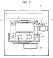
- Figs. 1 and 2 are a right-hand side opened-up view and a front opened-up view, respectively, of an image reading apparatus 1 in accordance with the present invention.
- the image reading apparatus 1 is provided with an apparatus body 2 and a carrier member 3 which holds a film-shaped transparency original such as a photographic film and a microfilm.
- This image reading apparatus 1 is connected to an image display device (not shown) of a computer apparatus or the like via an interface line for data transfer (e.g., a SCSI line), and is so arranged as to permit so-called previewing in which, prior to high-accuracy reading of image data (hereafter referred to as the "final image reading"), image data of all of the transparency original 4 (see Fig.
- the image display device is capable of storing the image data in correspondence with each frame in the carrier member 3, and is capable of displaying on the display one image of each frame at a time or a plurality of images simultaneously.
- the user is capable of specifying an image subject to reading on the display, and by designating the frame of the image, the user is capable of effecting the final image reading.
- the apparatus body 2 comprises a carrier insertion port 11 provided in its body casing K so as to insert the carrier member 3; a carrier frame 12 holding the carrier member 3 inserted through the carrier insertion port 11 and guiding the carrier member 3 into the interior of the body casing K; an illuminating unit (projecting unit) 13 illuminating light to the transparency original 4 which is held by the carrier member 3; a base 14 moving the carrier frame 12; a power supply unit 15 supplying electric power to the respective units; a printed circuit board 16 on which a digital processing circuit for effecting various items of digital processing is mounted; a power supply switch 17; and a connector 18 for connection to an interface line for data transfer.
- a carrier insertion port 11 provided in its body casing K so as to insert the carrier member 3
- a carrier frame 12 holding the carrier member 3 inserted through the carrier insertion port 11 and guiding the carrier member 3 into the interior of the body casing K
- an illuminating unit (projecting unit) 13 illuminating light to the transparency original 4 which is held
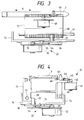
- a carrier guide unit (carrier moving means) 21 moving the carrier member 3 and guiding the same to an image reading position so as to allow a CCD (image reading means) 25 to read image data at the time of previewing.
- a carrier-frame guide unit (carrier-frame moving means) 22 moving the carrier frame 12 and guiding the carrier member 3 to the image reading position so as to allow the CCD 25 to read the image data during the final image reading;
- a reflecting plate 23 allowing the light emitted from the illuminating unit 13 and transmitted through the transparency original 4 to be reflected substantially at an angle of 90°;
- a focusing lens 24 focusing the light reflected by the reflecting plate 23; and the CCD 25 effecting photoelectric conversion of the light focused by the focusing lens 24.
- the carrier insertion port 11 is formed in such a way that its upper side wall 11a is inclined, and the arrangement provided is such that as the carrier member 3 is inserted along the side wall 11a, the carrier member 3 can be easily guided to the carrier frame 12.
- the base 14 is fixed to the body casing K.
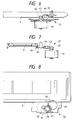
- the arrangement provided is such that the carrier frame 12 can be moved along a pair of shafts 31 fixed inside the body casing K in parallel with a moving direction A (see Fig. 3) of the carrier member 3. Specifically, as respectively shown in Figs.
- a first motor 32 which is a stepping motor moving the carrier frame 12
- a second gear 34 meshing with a first gear 33 which is axially secured to a motor shaft of the first motor 32
- a third gear 36 which meshes with a small-diameter gear 35 provided coaxially on the second gear 34 and which has a small-diameter gear 37 provided coaxially therewith.
- a rack 38 meshing with the small-diameter gear 37 is formed on a lower portion of an inner side surface of a left-hand body of the carrier frame 12.
- the carrier-frame guide unit 22 is so arranged as to be capable of moving the carrier frame by a one-fourth (although not particularly limited) frame portion of the transparency original 4 fitted in the carrier member 3. Consequently, effective use is made of the internal space of the apparatus body 2.
- the first motor 32 and the various gears 33 to 37 form the aforementioned carrier-frame guide unit 22.
- the carrier frame 12 is so arranged as to be capable of guiding the carrier member 3, from its front end to its rear end, inside the body casing K.
- the carrier frame 12 comprises a second motor 41 which is a stepping motor moving the carrier member 3, a fifth gear 43 meshing with a fourth gear 42 which is axially secured to a motor shaft of the second motor 41, and a sixth gear 45 meshing with a small-diameter gear 44 which is provided coaxially on the fifth gear 43.
- a rack 46 meshing with the sixth gear 45 is formed on a thicknesswise substantially central portion of a right-hand side surface of the carrier member 3 in Fig. 4 (see Figs. 8 and 12).
- the second motor 41 when the second motor 41 is driven, power is transmitted to the carrier member 3 via the fourth gear 42, the fifth gear 43, the small-diameter gear 44, the sixth gear 45, and the rack 46. Consequently, the carrier member 3 moves inside the body casing K in a state of being held on the carrier frame 12.
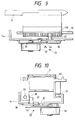
- the distance by which the carrier frame 12 moves by the one-step rotation of the second motor 41 is set to be greater than the distance by which the carrier member 3 moves by the one-step rotation of the first motor 32. Consequently, during previewing, the speed at which image data is read is fast due to the fast movement of the carrier member 3, with the result that the specification of an object of reading during previewing can be effected quickly.
- the second motor 41 and the various gears 42 to 45 form the aforementioned carrier guide unit 21.
- the carrier member 3 is formed to be thin and elongated.
- the carrier member 3 comprises six (although particularly not limited) original windows 51; projections 52 with rectangular cross sections each formed on either side of each original window 51 and projecting in the upward direction of a fitting surface (toward this side in the plane of the drawing in Fig. 12(a)); and a pair of projections 53 with rectangular cross sections formed on respective longitudinally opposite end sides of the two original windows 51 located at longitudinally opposite ends (upper and lower ends in the same drawing) of the carrier member 3, and projecting in the upward direction of the fitting surface.
- the transparency original 4 With this carrier member 3, by fitting the transparency original 4 between the projections 52 and between the projections 53, the transparency original 4 can be secured in the carrier member 3 in a state of being nipped by the projections 52 and by the projections 53. Further, by fitting a transparent plastic plate (not shown) between the projections 52 and between the projections 53, the transparency original 4 can be nipped from its obverse and reverse sides by the base surface of the carrier member 3 and the plastic plate, thereby preventing the deflection of the transparency original 4.
- the arrangement provided is such that since a photographic film or the like is generally divided for each six frames during a printing service, in this carrier member 3, each frame of the transparency original 4 is located immediately above each original window 51 when the six-frame portion of the transparency original 4 is fitted in. As a result, when light is radiated from the illuminating unit 13, its transmitted light reaches the reflecting plate 23 via the transparency original 4 and the original window 51.
- hole portions 54 and 55 are respectively formed in a front end portion (the upper side in the same drawing) and a rear end portion as viewed in the longitudinal direction of the carrier member 3.
- a pair of projections 56, as well as a pair of projections 57 each having the same shape as that of the aforementioned projection 53, are formed at each transversely opposite end side of each of the hole portions 54 and 55 and at each longitudinally opposite end side of the carrier member 3, respectively.
- the brown base film which is an unrecorded portion of the negative film, between the pair of projections 56 and between the two projections 53 and 57, the brown base film can be secured in the carrier member 3 in a state of being nipped by the projections 56 and by the projections 53 and 57.
- the brown base film can be nipped from its obverse and reverse sides by the base surface of the carrier member 3 and the plastic plate.
- the brown base film covers the hole portion 57, the density of light transmitted through the brown base film is detected by the CCD 25, and the shading correction of the image and white reference adjustment can be adjusted on the basis of that density.
- the transparency original 4 and the brown base film are nipped from their obverse and reverse sides by the plastic plate and the base surface, the deflection of the transparency original 4 and the brown base film can be effectively prevented, and the reading conditions for image data can be set to be identical, with the result that correction data at that time of adjustment of the shading correction of the image and white reference adjustment can be generated accurately.
- the plastic plate and the base surface which forms edges of the window 54 (or 55) nip the brown base film along the main scanning direction (the direction of the line of arrangement of the CCD 25, i.e., the direction indicated by arrow B in Fig.
- the hole portions 54 and 55 are formed in the longitudinally opposite end portions of the carrier member 3, in whichever direction the carrier member 3 moves in the direction A, the shading correction of the image and the white reference adjustment are made possible.
- the hole portions 54 and 55 may be made to function as reference holes for determining the image reading position.
- a notch 58 for positioning the transparency original 4 located at the hole portion 55 to the image reading position is formed in a side surface (thickness surface) of the carrier member 3 in the vicinity of an intermediate portion of the original window 51 close to the hole portion 55.
- an interrupter (not shown) is disposed in the body casing, and if the interrupter detects the passage of the front end portion of the carrier member 3 and the slit 58, a main CPU 71 (see Fig. 13) outputs a drive signal for motor driving to the second motor 41 on the basis of the passage detection signal, thereby making it possible to effect the positioning of the transparency original 4.
- the aforementioned illuminating unit 13 is provided with an inverter circuit 61, xenon lamps 62, 63, and 64 which are light sources at the time of image reading, and a diffusion plate 65 diffusing the light from the xenon lamps 62, 63, and 64.
- the xenon lamps 62, 63, and 64 are respectively controlled so as to be lit in a fixed order by a lamp control unit 81 (see Fig. 13), and emit light having wavelengths of blue, green and red colors.
- the three colors of light which have been transmitted through the transparency original 4 are respectively photoelectrically converted by the CCD 25, and image data of a color image is stored for each of the three colors in a buffer RAM 82 (see Fig.
- the light sources are not limited to the xenon lamps, and, among others, three LEDs capable of respectively emitting the aforementioned three colors, or a fluorescent lamp capable of emitting light including the three colors of light, may be used, for example.
- the circuit block diagram shown in the drawing shows a main circuit including a control circuit 70 of the image reading apparatus 1, each electrical circuit part is mounted on the aforementioned printed circuit board 16.
- the control circuit comprises the main CPU (read controlling means) constituting the nucleus of various items of processing; an image processing gate array 72 executing image processing under control by the main CPU 71; an A/D conversion unit 73 effecting the A/D conversion of an image signal outputted from the CCD 25; an interface unit 74 converting the image data and various signals to data of a predetermined communication format and receiving and transmitting the converted data between the main CPU 71 and the image display device of a host computer; and a first motor driver 75 and a second motor driver 76 respectively driving the first and second motors 32 and 41 on the basis of the drive signal from the main CPU 71.
- the main CPU 71, the image processing gate array 72, and the CCD 25 form the image reading means in the present invention.
- the gate array 72 is provided with the lamp control unit 81 controlling the lighting of the xenon lamps 62 to 64 by outputting lighting control signals via the inverter circuit 61; the buffer RAM 82 storing the image data; an image control unit 83 fetching the image data outputted from the A/D conversion unit 73 and causing the buffer RAM 82 to store the same in correspondence with the respective pixels, and executing the shading correction of the image, white/black reference adjustment, and the like; and a CCD control unit 84 controlling the photoelectric conversion of the CCD 25 by outputting a CCD control signal in response to a storage interval signal, a sift signal, and a clock signal outputted from the main CPU 71.
- the interrupter When the carrier member 3 is inserted in the carrier insertion port 11, as its front end portion passes the interrupter, the interrupter outputs a passage detection signal to the main CPU 71.
- the main CPU 71 outputs a drive signal to drive the second motor 41, thereby guides the carrier member 3 to a predetermined standby position inside the body casing K.
- a preview signal (a batch read command, an image read command) is outputted from the image display device via the interface unit 74
- the main CPU 71 outputs a drive signal to the second motor driver 76 to drive the second motor 41, and moves the carrier member 3 until a signal representing the detection of passage of the front end portion is outputted.
- the main CPU 71 causes the image data from the CCD 25 to be read by the image control unit 83 by outputting a CCD control signal without lighting the xenon lamps 62 to 64. Then, the main CPU 71 causes the image control unit 83 to set the image data at this time to the luminance level of a 0 gradation, thereby effecting black level adjustment.
- the luminance level of the image data is set to 256 gradations for each color, and the 0 gradation corresponds to the black level and the 255 gradation to the white level.
- the main CPU 71 causes the xenon lamps 2 to 64 to be consecutively lit up one by one, and causes the image control unit 83 to consecutively read the image data of R, G, and B from the CCD 25.
- the main CPU 71 effects white level adjustment by adjusting the driving speed of the second motor 41 and adjusting the light-up time durations of the xenon lamps 62 to 64, respectively, in accordance with a g -table stored in a built-in ROM, such that a maximum value of the image data which is read at this time becomes a gradation of 130 to 150 or thereabouts.
- the main CPU 71 causes the image control unit 83 to execute shading correction.
- correction data is generated so that the image data in one row of the CCD 25 is uniformly set to 256 gradations, on the basis of the light quantities of the xenon lamps 62 to 64, the reflection coefficient of the reflecting late 23, aberrations of the focusing lens 24, and the like.
- the correction data is automatically generated such that when the brown base film of the negative film is fitted in the hole portion 54, the luminance of the light transmitted through the brown base film is set as the white level, and when the brown base film is not fitted, the luminance of the light which has directly passed the hole portion 54 is set to the white level.
- the dynamic range of the luminance level of the image data can be automatically can be made largest.
- the main CPU 71 outputs a drive signal to move the carrier member 3 so as to allow an end of a leading (first) original window 51 to be located at the beginning of the reading position, and the reading of the image is then started.
- various parameters are outputted from the main CPU 71 to the lamp control unit 81, whereupon the lamp control unit 81 outputs a lighting control signal to the inverter circuit 61, thereby allowing the xenon lamps 62 to 64 to be consecutively lit up one by one.
- the main CPU 71 While outputting the drive signal and the CCD control signal, the main CPU 71 causes the image control unit 83 to consecutively read the image data of R, G, and B of the image.
- the image data which has been read is subjected to shading correction, color correction, and enlargement/reduction processing by the image control unit 83, and is then temporarily stored in the buffer RAM 82. Then, the main CPU 71 reads the image data stored in the buffer RAM 82, and outputs the same to the interface unit 74. At the same time, the interface unit 74 converts the image data to data of a predetermined communication format, and outputs the converted data to the image display device.
- the main CPU 17 continuously outputs the drive signal to rotate the second motor 41 by a predetermined number of steps, thereby moving the carrier member 3 such that the end of the second original window 51 is located at the beginning of the reading position. Then, the main CPU 71 outputs various parameters to the lamp control unit 81 and the image control unit 83, respectively, thereby allowing the image control unit 83 to read the image data of the transparency original 4. By repeating these processings, the main CPU 71 consecutively causes the image data of the transparency original 4 at the third to sixth original windows to be read, and outputs the image data to the interface unit 74 on each such occasion.
- the image display device stores the inputted image data in an image data RAM (not shown), and when a predetermined keying operation is performed, the image on the transparency original 4 at the designated original window 51 is displayed on a display unit.
- a frame designation signal (frame designation command) is outputted from the image display device to the main CPU 71 via the interface unit 74.
- the main CPU 71 outputs a drive signal to the second motor driver 76 to drive the second motor 41 by a predetermined number of steps, thereby guiding the carrier member 3 so that the original window 51 of the designated frame is located at the beginning of the reading position.
- the main CPU 17 starts the final image reading, and outputs a drive signal to the first motor driver 75, thereby driving the first motor 32 by a predetermined number of steps such that the carrier frame 12 is moved by a one-frame portion of the original window 51.
- the main CPU 71 outputs the lighting control signal and the CCD control signal, thereby executing the aforementioned shading processing and reading the image data.
- the image can be read with high accuracy.
- the image data which has been read is displayed to the image display device via the interface unit 74 by the main CPU 71 in the same way as described above.
- the image display device effects such as display processing of the image on the basis of the image data, image processing/correction processing such as luminance adjustment of the image data, fit processing in which an image on an arbitrary frame is fitted in an image on another frame, and the processing of writing in a storage medium such as MO (magneto-optical disk), DAT, MD, and a floppy disk.
- a storage medium such as MO (magneto-optical disk), DAT, MD, and a floppy disk.
- the carrier moving means and the carrier-frame moving means are formed by the motors 32 and 41 and various gears, the present invention is not limited to the same, and these means may be arranged by a combination of a motor, a link mechanism, and a belt mechanism.
- a display unit such as a liquid-crystal panel or a cathode-ray tube may be provided in the image reading apparatus 1, and an image may be displayed on the display unit serving as the image display device.
- an arrangement may be provided such that the apparatus body 2 is provided with an operation switch, and these commands are outputted by the operation of the operation switch.
- the read controlling means causes the image reading means to continuously read a transparency original having a plurality of frames
- the user is capable of easily specifying a frame of the transparency original for which image reading is desired among the plurality of frames of the transparency original held in the carrier member, by causing the image display device to display the image on the transparency original which has been read and by making confirmation on the displayed image. For this reason, it is possible to eliminate the troublesome operation in which each of the frames must be moved to automatically read the plurality of frames continuously.
- the read controlling means causes the image reading means to continuously read a plurality of designated frames or one specific frame of the transparency original
- the user is capable of easily specifying a frame of the transparency original for which image reading is desired among the plurality of frames of the transparency original held in the carrier member, by causing the image display device to display the image on the transparency original which has been read and by making confirmation on the displayed image. For this reason, it is possible to eliminate the troublesome operation in which each of the frames must be moved to automatically read the plurality of frames continuously.
- the user by, for example, effecting frame designation by the operation switch, the user is capable of causing the image reading means to read image data of an arbitrary frame from the transparency original having the plurality of frames.
- the carrier member together with the carrier frame is moved by the carrier-frame moving means, by enlarging the insertion port, the insertion of the carrier member into the image reading apparatus can be facilitated, and a frame-designated image can be read with high accuracy.
Landscapes
- Engineering & Computer Science (AREA)
- Multimedia (AREA)
- Signal Processing (AREA)
- Facsimile Scanning Arrangements (AREA)
- Facsimiles In General (AREA)
Applications Claiming Priority (3)
| Application Number | Priority Date | Filing Date | Title |
|---|---|---|---|
| JP07373896A JP3649506B2 (ja) | 1996-03-28 | 1996-03-28 | 画像読取装置 |
| JP73738/96 | 1996-03-28 | ||
| PCT/JP1997/001068 WO1997036418A1 (fr) | 1996-03-28 | 1997-03-27 | Lecteur d'images |
Publications (2)
| Publication Number | Publication Date |
|---|---|
| EP0830002A1 true EP0830002A1 (fr) | 1998-03-18 |
| EP0830002A4 EP0830002A4 (fr) | 1999-11-17 |
Family
ID=13526889
Family Applications (1)
| Application Number | Title | Priority Date | Filing Date |
|---|---|---|---|
| EP97908536A Withdrawn EP0830002A4 (fr) | 1996-03-28 | 1997-03-27 | Lecteur d'images |
Country Status (4)
| Country | Link |
|---|---|
| US (1) | US6335808B1 (fr) |
| EP (1) | EP0830002A4 (fr) |
| JP (1) | JP3649506B2 (fr) |
| WO (1) | WO1997036418A1 (fr) |
Families Citing this family (1)
| Publication number | Priority date | Publication date | Assignee | Title |
|---|---|---|---|---|
| US7595918B2 (en) * | 2002-08-27 | 2009-09-29 | Canon Kabushiki Kaisha | Transparent original reading apparatus and illuminating apparatus for reading apparatus |
Citations (4)
| Publication number | Priority date | Publication date | Assignee | Title |
|---|---|---|---|---|
| EP0530027A2 (fr) * | 1991-08-30 | 1993-03-03 | Nikon Corporation | Système de digitalisation d'une image |
| WO1996025004A1 (fr) * | 1995-02-08 | 1996-08-15 | Sony Corporation | Lecteur d'images |
| EP0804013A2 (fr) * | 1996-04-26 | 1997-10-29 | Konica Corporation | Lecteur de film |
| EP0848542A2 (fr) * | 1996-12-13 | 1998-06-17 | Fuji Photo Film Co., Ltd. | Dispositif de formation d'image |
Family Cites Families (10)
| Publication number | Priority date | Publication date | Assignee | Title |
|---|---|---|---|---|
| US4786980A (en) * | 1985-06-24 | 1988-11-22 | Canon Kabushiki Kaisha | Image information recording system |
| GB8531157D0 (en) * | 1985-12-18 | 1986-01-29 | British Gas Corp | Recuperative burners |
| US5926289A (en) * | 1991-08-30 | 1999-07-20 | Nikon Corporation | Image digitizing system |
| JPH06311321A (ja) * | 1993-04-21 | 1994-11-04 | Konica Corp | フィルム画像読取り装置 |
| JPH06337479A (ja) * | 1993-05-31 | 1994-12-06 | Fuji Photo Film Co Ltd | 画像プリント条件決定装置 |
| US5461492A (en) * | 1994-02-16 | 1995-10-24 | Eastman Kodak Company | Film scanner with in-line dual scanning gates |
| JPH07288826A (ja) * | 1994-04-15 | 1995-10-31 | Minolta Co Ltd | フィルム画像再生装置 |
| JPH0837618A (ja) * | 1994-07-25 | 1996-02-06 | Nikon Corp | 原稿ホルダー |
| JPH08214103A (ja) * | 1995-02-08 | 1996-08-20 | Konica Corp | 画像情報読取装置 |
| JP3596789B2 (ja) * | 1995-10-16 | 2004-12-02 | 富士写真フイルム株式会社 | 画像読取処理装置 |
-
1996
- 1996-03-28 JP JP07373896A patent/JP3649506B2/ja not_active Expired - Fee Related
-
1997
- 1997-03-27 EP EP97908536A patent/EP0830002A4/fr not_active Withdrawn
- 1997-03-27 US US08/973,148 patent/US6335808B1/en not_active Expired - Fee Related
- 1997-03-27 WO PCT/JP1997/001068 patent/WO1997036418A1/fr not_active Application Discontinuation
Patent Citations (4)
| Publication number | Priority date | Publication date | Assignee | Title |
|---|---|---|---|---|
| EP0530027A2 (fr) * | 1991-08-30 | 1993-03-03 | Nikon Corporation | Système de digitalisation d'une image |
| WO1996025004A1 (fr) * | 1995-02-08 | 1996-08-15 | Sony Corporation | Lecteur d'images |
| EP0804013A2 (fr) * | 1996-04-26 | 1997-10-29 | Konica Corporation | Lecteur de film |
| EP0848542A2 (fr) * | 1996-12-13 | 1998-06-17 | Fuji Photo Film Co., Ltd. | Dispositif de formation d'image |
Non-Patent Citations (1)
| Title |
|---|
| See also references of WO9736418A1 * |
Also Published As
| Publication number | Publication date |
|---|---|
| JPH09266520A (ja) | 1997-10-07 |
| WO1997036418A1 (fr) | 1997-10-02 |
| JP3649506B2 (ja) | 2005-05-18 |
| US6335808B1 (en) | 2002-01-01 |
| EP0830002A4 (fr) | 1999-11-17 |
Similar Documents
| Publication | Publication Date | Title |
|---|---|---|
| US7164437B2 (en) | Film scanner | |
| EP0804013B1 (fr) | Lecteur de film | |
| US5140445A (en) | Imaging reading apparatus having a preheating system | |
| US4930009A (en) | Method of making a print of color slide | |
| US7164508B2 (en) | Image reading apparatus | |
| US6972877B1 (en) | Image reading apparatus | |
| US6335808B1 (en) | Image reading apparatus | |
| US6404515B1 (en) | Image reading apparatus | |
| US20010014219A1 (en) | Photographic and video image system | |
| US6819799B1 (en) | Image reading apparatus, original reading method and original conveyance apparatus | |
| US6879372B1 (en) | Image processing apparatus and method thereof | |
| JPH09266522A (ja) | 原稿装着装置 | |
| JP3668061B2 (ja) | 画像読取装置 | |
| JPH09294178A (ja) | 画像読取装置 | |
| JPH09266519A (ja) | 原稿装着装置および画像読取装置 | |
| JP3805137B2 (ja) | 画像読取装置及び画像読取方法 | |
| JP3386394B2 (ja) | 写真プリント装置 | |
| JP2810408B2 (ja) | 画像読取装置 | |
| JPH09266521A (ja) | 原稿装着装置 | |
| JPH09247316A (ja) | フイルムスキャナ | |
| JPH09266524A (ja) | 原稿装着装置 | |
| AU767656B2 (en) | Photographic image system | |
| JP2001211295A (ja) | 画像読取方法及び装置並びに記憶媒体 | |
| JPH09266523A (ja) | 画像読取装置 | |
| JPH02295374A (ja) | 画像読取装置 |
Legal Events
| Date | Code | Title | Description |
|---|---|---|---|
| PUAI | Public reference made under article 153(3) epc to a published international application that has entered the european phase |
Free format text: ORIGINAL CODE: 0009012 |
|
| 17P | Request for examination filed |
Effective date: 19971128 |
|
| AK | Designated contracting states |
Kind code of ref document: A1 Designated state(s): DE FR GB |
|
| A4 | Supplementary search report drawn up and despatched |
Effective date: 19990930 |
|
| AK | Designated contracting states |
Kind code of ref document: A4 Designated state(s): DE FR GB |
|
| 17Q | First examination report despatched |
Effective date: 20041216 |
|
| STAA | Information on the status of an ep patent application or granted ep patent |
Free format text: STATUS: THE APPLICATION IS DEEMED TO BE WITHDRAWN |
|
| 18D | Application deemed to be withdrawn |
Effective date: 20071002 |