EP0827925B1 - Bogenanleger an Druckmaschinen - Google Patents
Bogenanleger an Druckmaschinen Download PDFInfo
- Publication number
- EP0827925B1 EP0827925B1 EP97113928A EP97113928A EP0827925B1 EP 0827925 B1 EP0827925 B1 EP 0827925B1 EP 97113928 A EP97113928 A EP 97113928A EP 97113928 A EP97113928 A EP 97113928A EP 0827925 B1 EP0827925 B1 EP 0827925B1
- Authority
- EP
- European Patent Office
- Prior art keywords
- carrier
- pile
- sheet
- unit
- alignment
- Prior art date
- Legal status (The legal status is an assumption and is not a legal conclusion. Google has not performed a legal analysis and makes no representation as to the accuracy of the status listed.)
- Expired - Lifetime
Links
- 238000006073 displacement reaction Methods 0.000 description 3
- 238000010276 construction Methods 0.000 description 1
- 238000009434 installation Methods 0.000 description 1
- 238000000926 separation method Methods 0.000 description 1
- 239000000725 suspension Substances 0.000 description 1
Images


Classifications
-
- B—PERFORMING OPERATIONS; TRANSPORTING
- B65—CONVEYING; PACKING; STORING; HANDLING THIN OR FILAMENTARY MATERIAL
- B65H—HANDLING THIN OR FILAMENTARY MATERIAL, e.g. SHEETS, WEBS, CABLES
- B65H1/00—Supports or magazines for piles from which articles are to be separated
- B65H1/26—Supports or magazines for piles from which articles are to be separated with auxiliary supports to facilitate introduction or renewal of the pile
- B65H1/266—Support fully or partially removable from the handling machine, e.g. cassette, drawer
-
- B—PERFORMING OPERATIONS; TRANSPORTING
- B65—CONVEYING; PACKING; STORING; HANDLING THIN OR FILAMENTARY MATERIAL
- B65H—HANDLING THIN OR FILAMENTARY MATERIAL, e.g. SHEETS, WEBS, CABLES
- B65H1/00—Supports or magazines for piles from which articles are to be separated
- B65H1/08—Supports or magazines for piles from which articles are to be separated with means for advancing the articles to present the articles to the separating device
- B65H1/18—Supports or magazines for piles from which articles are to be separated with means for advancing the articles to present the articles to the separating device controlled by height of pile
-
- B—PERFORMING OPERATIONS; TRANSPORTING
- B65—CONVEYING; PACKING; STORING; HANDLING THIN OR FILAMENTARY MATERIAL
- B65H—HANDLING THIN OR FILAMENTARY MATERIAL, e.g. SHEETS, WEBS, CABLES
- B65H2801/00—Application field
- B65H2801/03—Image reproduction devices
- B65H2801/21—Industrial-size printers, e.g. rotary printing press
Definitions
- the invention relates to a sheet feeder with laterally adjustable stack support plates on sheet-processing machines according to the preamble of the claim 1.
- the stack support plate is, for example, on a Frame slidably mounted or designed as a double plate, the Upper part is displaceable relative to the lower part.
- a sheet feeder on printing machines is known from DE 29 11 735 A1.
- a frame for a stack support plate is provided, on which this laterally is movably arranged by means of an actuator.
- the auxiliary pile support device consisting of support rails for individual bars that are under the rest of the stack are inserted, is arranged laterally displaceable.
- the mounting rails rest on side rails and can be moved on them by means of an actuator.
- This sheet feeder has the disadvantage that it consists of conventional Hoists exist that take up large installation space. A hint for Devices for compact designs for the use of any stacking aids such as pallets or mobile stacking tables is not available.
- DE 19 10 160 A describes a device for the lateral alignment of a Sheet feed table known, which corresponds to the preamble of claim 1 or 2.
- a Sheet feed table known, which corresponds to the preamble of claim 1 or 2.
- the stacking table is on wheels in the sheet feeder movable and laterally movable on the rollers in the sheet feeder.
- FR 2 382 390 A describes a device for the lateral alignment of a Sheet stack known in a sheet feeder.
- the device instructs one Chains suspended on the stacking support plate, which are attached to the Chains for laterally aligning the stack is slidable.
- the object of the invention is a sheet feeder according to the preamble of To improve claim 1 in such a way that in a confined space within from the frame side walls of the sheet feeder to the side Shift of any usable stacking aids is created.
- the solution is designed according to the characterizing part of claim 1 or 2.
- a stack support plate or a stack support frame and their Separation from the main stacking hoist is both a space saver for a compact Device as well as stability of the whole unit for larger loads. This comes in particular from the flexible processing of the sheet stacks any stacking means. Simple transport pallets can be used and also mobile stacking tables. Operation is simple and safe. The centering and tracking of the sheet stacks according to the specifications of the sheet processing company Machine is easily over guide rails possible.
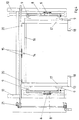
- the sheet feeder 1 shows a sheet feeder 1 according to the invention. He instructs Main stacker 2, a suction head 3 for separating the sheets from the top of the stack and a sheet guide table 4 to a sheet processing machine on.
- the sheet feeder 1 has fixed frame side walls 10.
- a stack of sheets S is on a stack support plate 5 of the main stacking mechanism 2 by means of a pallet P used.
- the main stacker 2 is with dashed lines shown and points on both sides of the sheet feeder 1 i.e. on each side of the frame 10 a lifting chain 6 as well as a lifting gear rail 7 and supporting elements 8 for the stack support plate 5.
- the support elements 8 contain a cross member, which in Arranged in the longitudinal direction of the sheet feeder 1 and with supports for the stack support plate 5 is provided.
- the stack support plate 5 can be lowered to the floor and is with a leading edge for driving with a stack transport Mistake.
- a transport pallet P can thus simply be placed on the stack support plate 5 be provided in the sheet feeder 1 for processing.
- the stack support plate 5 is provided with laterally protruding alignment rails 9, arranged in the transverse direction to the sheet feeder 1 in the support elements 8 reach in and are slidably mounted there.
- the alignment rails 9 are formed so that the stack support plate 5 in the lowest position of the support elements 8 rests on the floor on the stacker 2.
- a transport pallet P is set down, for example a sheet stack S can carry.
- the position of the sheet stack S relative to the sheet feeder 1 is through Displacement of the stack support plate 5 adjustable.
- the support elements 8 are arranged on the hoist rails 7 in such a way that the alignment rails 9 of the stack support plate 5 are placed thereon can be.
- an alignment axis 11 is attached to each support element 8.
- the alignment axis 11 can be as a rigid support rail or as rotatable element. Useful for a simple construction and that Aligning large loads e.g. with a full sheet stack S the use of individual rollers on each alignment rail 9.
- the alignment means per se are not shown in FIG. 2. This can be done accordingly the prior art, a motor fastened to the support element 8 with an actuating gear his. Manual alignment can also be specified.
- a set of stack alignment rails 20 is used, however, as is shown in FIG. 1 is shown.
- the function of the stack alignment rails 20 perpendicular to the front Stack edges of the sheet stack S act, is shown below.
- an alignment is the stack support plate 5 via an adjusting device in the form of an adjusting spindle 12 connected to the support device 8.
- Such adjusting spindles 12 can only a corner of the stack support plate 5 when the alignment rails 9 Provide a straight guide at the other corners of the stack support plate 5 are, so that the stack support plate 5 can not tilt when moving.
- the alignment rails 9 described above can be provided on rollers his.
- a support frame 13 for lifting Stacking means provided.
- the support frame 13 consists of several profiles 16, 17, 18.
- the support frame 13 is on the back of the sheet feeder 1, i.e. from the side of the stack feeder, open and only with short support legs 18 provided.
- the side profiles 17 of the support frame 13 are directly with the alignment rails 9 connected, as described above on the support elements 8 of the stacking mechanism 2 rest.
- the frame 13 is on its front profile element 16 to the sheet processing machine provided with a guide lug 14 which is in an alignment link 15 on the feeder frame intervenes.
- the lateral displacement of the support frame 13 can be analogous how to move the stack support plate 5 described above.
- a supporting frame 13 e.g. a stacking table can be used with rollers. This can independently in the sheet feeder 1 can be retracted where the supporting frame takes it over in the simplest way and for processing by the suction head 3.
- Centering of the stacking table is provided by means of a center guide in the sheet feeder 1 be to facilitate the pre-alignment of the sheet stack S.
- the guide projection 14 is in a guide link 15 laterally centered as long as the support frame 13 in Recording position is on the floor. So the sheet stack S in one after positioning that can be aligned equally on both sides.
- the stack orientation in the lateral direction is thus from a centered position the support frame 13, which can also be provided for the stack support plate 5, executed from.
- the two stack alignment rails 20 by means of the drive 21 driven against the front vertical edges of the sheet stack S. and keep it aligned sideways and lengthways.
- the stack alignment rails 20 are both relative to each other and common by means of the drive 21 slidable in one direction. This makes the sheet stack S both held transversely as well as transversely displaceable, including the transport pallet and Stack support plate 5 moves on the alignment rails 9 and the alignment axes 11 becomes. An adjusting device as in Fig. 3 is then not required.
- the sheet stack can be guided according to FIGS. 1 to 3 and FIG. 4 be distinguished.
- the first version which uses a stack support plate 5
- only flat stack alignment rails 20 are provided for the sheet stack S, since these are supposed to work together with a simple transport pallet.
- the second case when using the rollable stacking table it can be designed in this way be that recesses are provided on its front edge. In these recesses can then correspond to the angular stack alignment rails 20 Fig. 4 intervene.
- the sheet stack S stands in this area something about the stacking table.
- the recesses are for both stacking corners only so wide that the minimum intended for the sheet-processing machine and maximum sheet formats can be processed. So that's the front one Stack edge still sufficiently supported.
- the embodiments of the invention are not based on the variants shown of the support plate and frame displacement.
Landscapes
- Engineering & Computer Science (AREA)
- Mechanical Engineering (AREA)
- Sheets, Magazines, And Separation Thereof (AREA)
- Pile Receivers (AREA)
Description
- Fig. 1
- einen Bogenanleger in ganzer Darstellung,
- Fig. 2
- einen Stapeltragplatte und deren Aufhängung,
- Fig. 3
- ein Detail einer Stapeltragplatte und
- Fig. 4
- einen Stapeltragrahmen mit einer Anordnung von Führungsschienen im Bogenanleger.
Claims (8)
- Bogenanleger (1) an bogenverarbeitenden Maschinen, insbesondere an Bogenrotationsdruckmaschinen, mit Seitenwänden, einer Vereinzelungseinrichtung (3) und einem Hauptstapelhubwerk (2) mit einer Tragvorrichtung (5) für einen Bogenstapel (S), wobei die Tragvorrichtung (5) an als Teilen des Hauptstapelhubwerkes (2) ausgebildeteten Tragelementen (8) vertikal starr geführt ist, wobei Richtmittel vorgesehen sind, um einen auf der Tragvorrichtung (5) abgesetzten Bogenstapel (S) seitlich zu verschieben, indem die Tragvorrichtung (5) linear und quer zur Hubrichtung und zur Abtransportrichtung der Vereinzelungseinrichtung (3) verschiebbar mit jedem Tragelement (8) verbunden ist, wobei die Richtmittel als seitlich an der Tragvorrichtung (5) angeordnete Ausrichtschienen (9) vorgesehen sind, die linear und horizontal beweglich mit den Tragelementen (8) verbunden sind, und wobei an der Tragvorrichtung (5) und/oder dem Bogenstapel (S) angreifende Zentriermittel vorgesehen sind,
dadurch gekennzeichnet,
daß die Tragvorrichtung als durchgehende und befahrbare Stapeltragplatte (5) ausgebildet ist, wobei die Ausrichtschienen (9) derart von der Stapeltragplatte (5) abgewinkelt ausgeführt sind, daß die Stapeltragplatte (5) in ihrer untersten Stellung ebenerdig zu liegen kommt. - Bogenanleger (1) an bogenverarbeitenden Maschinen, insbesondere an Bogenrotationsdruckmaschinen, mit Seitenwänden, einer Vereinzelungseinrichtung (3) und einem Hauptstapelhubwerk (2) mit einer Tragvorrichtung (13) für einen Bogenstapel (S), wobei die Tragvorrichtung (13) an als Teilen des Hauptstapelhubwerkes (2) ausgebildeteten Tragelementen (8) vertikal starr geführt ist, wobei Richtmittel vorgesehen sind, um einen auf der Tragvorrichtung (13) abgesetzten Bogenstapel (S) seitlich zu verschieben, indem die Tragvorrichtung (13) linear und quer zur Hubrichtung und zur Abtransportrichtung der Vereinzelungseinrichtung (3) verschiebbar mit jedem Tragelement (8) verbunden ist, wobei die Richtmittel als seitlich an der Tragvorrichtung (13) angeordnete Ausrichtschienen (9) vorgesehen sind, die linear und horizontal beweglich mit den Tragelementen (8) verbunden sind, und wobei an der Tragvorrichtung (13) und/oder dem Bogenstapel (S) angreifende Zentriermittel vorgesehen sind,
dadurch gekennzeichnet,
daß die Tragvorrichtung als an der hinteren der Stapelzuführung dienenden Seite offener Tragrahmen (13) ausgebildet ist und daß der Tragrahmen (13) sich in Aufnahmeposition am Boden befindet. - Vorrichtung nach einem der Ansprüche 1 oder 2,
dadurch gekennzeichnet,
daß die Zentriermittel zur mittigen Führung der Stapeltragplatte (5) oder des Tragrahmens (13) zwischen den Tragelementen (8) in deren Position zur Beladung mit einem neuen Bogenstapel (S) vorgesehen sind. - Vorrichtung nach einem der Ansprüche 1 bis 3,
dadurch gekennzeichnet,
daß die Tragelemente (8) mittels wenigstens einer Spindel-Mutter-Verbindung (12) mit der Stapeltragplatte (5) bzw. dem Tragrahmen (13) verbunden sind. - Vorrichtung nach einem der Ansprüche 1 bis 4,
dadurch gekennzeichnet,
daß die Zentriermittel zur Führung des Bogenstapels (S) und zur Seitenverschiebung des Bogenstapels (S) vorgesehen sind. - Vorrichtung nach Anspruch 5,
dadurch gekennzeichnet,
daß die Zentriermittel als Stapelausrichtschienen (20) auf die vorderen vertikalen Seitenkanten des Bogenstapels (S) wirkend vorgesehen sind. - Vorrichtung nach Anspruch 6,
dadurch gekennzeichnet,
daß die Stapelausrichtschienen (20) seitlich relativ zueinander und gemeinsam verstellbar angeordnet sind. - Vorrichtung nach Anspruch 6 oder 7,
dadurch gekennzeichnet,
daß die Stapelausrichtschienen (20) als Winkelschienen ausgebildet sind und daß in einem mit den Winkelschienen zusammenarbeitenden Stapeltisch Ausnehmungen für die in Abtransportrichtung weisenden Schenkel der Winkelschienen vorgesehen sind, die so weit reichen, daß minimale bis maximale Bogenformate auf dem Stapeltisch verarbeitbar sind.
Applications Claiming Priority (2)
| Application Number | Priority Date | Filing Date | Title |
|---|---|---|---|
| DE19636187A DE19636187A1 (de) | 1996-09-06 | 1996-09-06 | Bogenanleger an Druckmaschinen |
| DE19636187 | 1996-09-06 |
Publications (3)
| Publication Number | Publication Date |
|---|---|
| EP0827925A2 EP0827925A2 (de) | 1998-03-11 |
| EP0827925A3 EP0827925A3 (de) | 1998-11-25 |
| EP0827925B1 true EP0827925B1 (de) | 2000-05-10 |
Family
ID=7804799
Family Applications (1)
| Application Number | Title | Priority Date | Filing Date |
|---|---|---|---|
| EP97113928A Expired - Lifetime EP0827925B1 (de) | 1996-09-06 | 1997-08-13 | Bogenanleger an Druckmaschinen |
Country Status (3)
| Country | Link |
|---|---|
| EP (1) | EP0827925B1 (de) |
| AT (1) | ATE192718T1 (de) |
| DE (2) | DE19636187A1 (de) |
Cited By (1)
| Publication number | Priority date | Publication date | Assignee | Title |
|---|---|---|---|---|
| CN102502289A (zh) * | 2011-10-19 | 2012-06-20 | 苏州佳世达电通有限公司 | 用于薄片介质体拾取的调节装置及应用其的拾取装置 |
Families Citing this family (1)
| Publication number | Priority date | Publication date | Assignee | Title |
|---|---|---|---|---|
| DE20107828U1 (de) | 2000-05-10 | 2001-12-20 | MAN Roland Druckmaschinen AG, 63075 Offenbach | Stapelkontrollstation und Datensystem in einer Logistik für Druckerein |
Family Cites Families (11)
| Publication number | Priority date | Publication date | Assignee | Title |
|---|---|---|---|---|
| DE367490C (de) * | 1921-08-07 | 1923-01-23 | Kleim & Ungerer | Selbsttaetige Bogenanlegemaschine |
| US2815209A (en) * | 1955-03-30 | 1957-12-03 | Harris Seybold Co | Sheet feeder pile support |
| DE1163346B (de) * | 1962-04-27 | 1964-02-20 | Heinrich Nicolaus Ges Mit Besc | Vorrichtung zum selbsttaetigen Ausrichten von Stapeln bogenfoermigen Arbeitsgutes beim Zufuehren in bogenverarbeitende Maschinen |
| DE1910160B2 (de) * | 1968-03-05 | 1973-03-15 | Adamovske Strojirny, N.P., Adamov (Tschechoslowakei) | Vorrichtung zum seitlichen ausrichten eines stapeltisches eines bogenanlegers |
| DE2200755C3 (de) * | 1972-01-07 | 1974-11-07 | Mabeg Maschinenbau Gmbh Nachf. Hense & Pleines Gmbh & Co, 6050 Offenbach | Vorrichtung zum selbsttätigen Ausrichten eines Bogenstapels |
| DD131549B1 (de) * | 1977-03-04 | 1979-12-27 | Frank Fichte | Vorrichtung zum seitlichen ausrichten des bogenstapels |
| DE7903524U1 (de) * | 1979-02-09 | 1980-06-12 | Georg Spiess Gmbh, 8906 Gersthofen | Bogenanleger |
| DE2911735A1 (de) * | 1979-03-26 | 1980-10-09 | Spiess Gmbh G | Bogenanleger |
| DE8514473U1 (de) * | 1985-05-15 | 1985-07-18 | Stahl Gmbh & Co Maschinenfabrik, 7140 Ludwigsburg | Vorrichtung zum veränderlichen Einstellen eines Seitenanschlages für Bogenstapel in einem Bogenstapelanleger |
| DE3622692A1 (de) * | 1986-07-05 | 1988-01-14 | Spiess Gmbh G | Bogenanleger |
| US4971311A (en) * | 1987-09-24 | 1990-11-20 | Komori Printing Machinery Co., Ltd. | Feeder for sheet-feed printing machine |
-
1996
- 1996-09-06 DE DE19636187A patent/DE19636187A1/de not_active Withdrawn
-
1997
- 1997-08-13 EP EP97113928A patent/EP0827925B1/de not_active Expired - Lifetime
- 1997-08-13 DE DE59701630T patent/DE59701630D1/de not_active Expired - Fee Related
- 1997-08-13 AT AT97113928T patent/ATE192718T1/de not_active IP Right Cessation
Cited By (2)
| Publication number | Priority date | Publication date | Assignee | Title |
|---|---|---|---|---|
| CN102502289A (zh) * | 2011-10-19 | 2012-06-20 | 苏州佳世达电通有限公司 | 用于薄片介质体拾取的调节装置及应用其的拾取装置 |
| CN102502289B (zh) * | 2011-10-19 | 2014-08-20 | 苏州佳世达电通有限公司 | 用于薄片介质体拾取的调节装置及应用其的拾取装置 |
Also Published As
| Publication number | Publication date |
|---|---|
| ATE192718T1 (de) | 2000-05-15 |
| DE59701630D1 (de) | 2000-06-15 |
| EP0827925A3 (de) | 1998-11-25 |
| DE19636187A1 (de) | 1998-03-12 |
| EP0827925A2 (de) | 1998-03-11 |
Similar Documents
| Publication | Publication Date | Title |
|---|---|---|
| EP3782929A1 (de) | Behälterstapellager-beschickungswagen | |
| EP0316568B1 (de) | Vorrichtung zum Abstapeln von Bögen | |
| DE3622692C2 (de) | ||
| DE3316050A1 (de) | Einrichtung zum transport von werkstueckpaletten | |
| DE4216123A1 (de) | Formatveränderbare Stapelstation für aufeinanderfolgend angelieferte Blatterzeugnisse | |
| EP0046492B1 (de) | Vorrichtung zum Manipulieren, insbesondere zum Aufstapeln oder Entstapeln von Gegenständen, insbesondere Glasscheiben | |
| EP0958216A1 (de) | Stapelwechselvorrichtung | |
| DE4100901C2 (de) | Bogenanleger für Rotationsdruckmaschinen | |
| EP0827925A2 (de) | Bogenanleger an Druckmaschinen | |
| EP2033735B1 (de) | Kompakter Werkstückwechsler | |
| EP3889087A1 (de) | Sammel- und weiterfördervorrichtung zum sammeln und weiterfördern von blattförmigen druckereiprodukten | |
| DE202020101753U1 (de) | Wechselvorrichtung für einen Wechsel von wenigstens zwei Werkstückauflagen für eine Bearbeitungsmaschine | |
| EP1132329B1 (de) | Vorrichtung zum Ausgleichen eines radialen Gewindespindelschlags eines Spindeltriebs | |
| EP0891936A1 (de) | Vorrichtung zum Wenden eines aus Flachmaterialien bestehenden Stapels | |
| DE3326552C2 (de) | ||
| EP0953529B1 (de) | Bogenrückhalter für einen Non-Stop-Stapelwechsler | |
| DE3943559C2 (de) | ||
| DE3914924C2 (de) | ||
| DE29818894U1 (de) | Vorrichtung zum horizontalen Bewegen eines Bogenstapels | |
| DE19544411C2 (de) | Kombinierte Transportsicherung und Vereinzelungsvorrichtung für gestapelte Blechplatinen | |
| DE29814126U1 (de) | Flexibel ausrüstbarer, platzsparender Einmaschinen-Werkstück-Wechsler mit integriertem Werkstückmagazin | |
| CH687376A5 (de) | Stack-Carrier fuer Druckanlagen. | |
| DE3106632A1 (de) | "vorrichtung zum beschicken von paletten" | |
| DE19636179A1 (de) | Bogenanleger an Druckmaschinen | |
| EP3888844A1 (de) | Wechselvorrichtung für einen wechsel von wenigstens zwei werkstückauflagen fü eine bearbeitungsmaschine |
Legal Events
| Date | Code | Title | Description |
|---|---|---|---|
| PUAI | Public reference made under article 153(3) epc to a published international application that has entered the european phase |
Free format text: ORIGINAL CODE: 0009012 |
|
| AK | Designated contracting states |
Kind code of ref document: A2 Designated state(s): AT BE CH DE FR GB IT LI NL SE |
|
| PUAL | Search report despatched |
Free format text: ORIGINAL CODE: 0009013 |
|
| RHK1 | Main classification (correction) |
Ipc: B65H 1/26 |
|
| AK | Designated contracting states |
Kind code of ref document: A3 Designated state(s): AT BE CH DE DK ES FI FR GB GR IE IT LI LU MC NL PT SE |
|
| 17P | Request for examination filed |
Effective date: 19981030 |
|
| 17Q | First examination report despatched |
Effective date: 19990129 |
|
| AKX | Designation fees paid |
Free format text: AT BE CH DE DK ES FI FR GB LI |
|
| GRAG | Despatch of communication of intention to grant |
Free format text: ORIGINAL CODE: EPIDOS AGRA |
|
| GRAG | Despatch of communication of intention to grant |
Free format text: ORIGINAL CODE: EPIDOS AGRA |
|
| GRAH | Despatch of communication of intention to grant a patent |
Free format text: ORIGINAL CODE: EPIDOS IGRA |
|
| GRAH | Despatch of communication of intention to grant a patent |
Free format text: ORIGINAL CODE: EPIDOS IGRA |
|
| RBV | Designated contracting states (corrected) |
Designated state(s): AT BE CH DE FR GB IT LI NL SE |
|
| ITF | It: translation for a ep patent filed | ||
| GRAA | (expected) grant |
Free format text: ORIGINAL CODE: 0009210 |
|
| AK | Designated contracting states |
Kind code of ref document: B1 Designated state(s): AT BE CH DE FR GB IT LI NL SE |
|
| REF | Corresponds to: |
Ref document number: 192718 Country of ref document: AT Date of ref document: 20000515 Kind code of ref document: T |
|
| REG | Reference to a national code |
Ref country code: CH Ref legal event code: EP |
|
| ET | Fr: translation filed | ||
| GBT | Gb: translation of ep patent filed (gb section 77(6)(a)/1977) |
Effective date: 20000510 |
|
| REF | Corresponds to: |
Ref document number: 59701630 Country of ref document: DE Date of ref document: 20000615 |
|
| PLBI | Opposition filed |
Free format text: ORIGINAL CODE: 0009260 |
|
| PLBF | Reply of patent proprietor to notice(s) of opposition |
Free format text: ORIGINAL CODE: EPIDOS OBSO |
|
| 26 | Opposition filed |
Opponent name: HEIDELBERGER DRUCKMASCHINEN AG Effective date: 20010209 |
|
| NLR1 | Nl: opposition has been filed with the epo |
Opponent name: HEIDELBERGER DRUCKMASCHINEN AG |
|
| PLBF | Reply of patent proprietor to notice(s) of opposition |
Free format text: ORIGINAL CODE: EPIDOS OBSO |
|
| REG | Reference to a national code |
Ref country code: GB Ref legal event code: IF02 |
|
| PGFP | Annual fee paid to national office [announced via postgrant information from national office to epo] |
Ref country code: CH Payment date: 20020717 Year of fee payment: 6 |
|
| PGFP | Annual fee paid to national office [announced via postgrant information from national office to epo] |
Ref country code: SE Payment date: 20020725 Year of fee payment: 6 Ref country code: NL Payment date: 20020725 Year of fee payment: 6 |
|
| PGFP | Annual fee paid to national office [announced via postgrant information from national office to epo] |
Ref country code: GB Payment date: 20020730 Year of fee payment: 6 |
|
| PGFP | Annual fee paid to national office [announced via postgrant information from national office to epo] |
Ref country code: BE Payment date: 20020801 Year of fee payment: 6 |
|
| PGFP | Annual fee paid to national office [announced via postgrant information from national office to epo] |
Ref country code: FR Payment date: 20020812 Year of fee payment: 6 |
|
| PLBL | Opposition procedure terminated |
Free format text: ORIGINAL CODE: EPIDOS OPPC |
|
| PLBP | Opposition withdrawn |
Free format text: ORIGINAL CODE: 0009264 |
|
| PLBM | Termination of opposition procedure: date of legal effect published |
Free format text: ORIGINAL CODE: 0009276 |
|
| STAA | Information on the status of an ep patent application or granted ep patent |
Free format text: STATUS: OPPOSITION PROCEDURE CLOSED |
|
| PG25 | Lapsed in a contracting state [announced via postgrant information from national office to epo] |
Ref country code: GB Free format text: LAPSE BECAUSE OF NON-PAYMENT OF DUE FEES Effective date: 20030813 |
|
| PG25 | Lapsed in a contracting state [announced via postgrant information from national office to epo] |
Ref country code: SE Free format text: LAPSE BECAUSE OF NON-PAYMENT OF DUE FEES Effective date: 20030814 |
|
| 27C | Opposition proceedings terminated |
Effective date: 20030329 |
|
| PG25 | Lapsed in a contracting state [announced via postgrant information from national office to epo] |
Ref country code: LI Free format text: LAPSE BECAUSE OF NON-PAYMENT OF DUE FEES Effective date: 20030831 Ref country code: CH Free format text: LAPSE BECAUSE OF NON-PAYMENT OF DUE FEES Effective date: 20030831 Ref country code: BE Free format text: LAPSE BECAUSE OF NON-PAYMENT OF DUE FEES Effective date: 20030831 |
|
| NLR2 | Nl: decision of opposition |
Effective date: 20030329 |
|
| BERE | Be: lapsed |
Owner name: *MAN ROLAND DRUCKMASCHINEN A.G. Effective date: 20030831 |
|
| PG25 | Lapsed in a contracting state [announced via postgrant information from national office to epo] |
Ref country code: NL Free format text: LAPSE BECAUSE OF NON-PAYMENT OF DUE FEES Effective date: 20040301 |
|
| EUG | Se: european patent has lapsed | ||
| GBPC | Gb: european patent ceased through non-payment of renewal fee |
Effective date: 20030813 |
|
| REG | Reference to a national code |
Ref country code: CH Ref legal event code: PL |
|
| PG25 | Lapsed in a contracting state [announced via postgrant information from national office to epo] |
Ref country code: FR Free format text: LAPSE BECAUSE OF NON-PAYMENT OF DUE FEES Effective date: 20040430 |
|
| NLV4 | Nl: lapsed or anulled due to non-payment of the annual fee |
Effective date: 20040301 |
|
| REG | Reference to a national code |
Ref country code: FR Ref legal event code: ST |
|
| PG25 | Lapsed in a contracting state [announced via postgrant information from national office to epo] |
Ref country code: IT Free format text: LAPSE BECAUSE OF NON-PAYMENT OF DUE FEES;WARNING: LAPSES OF ITALIAN PATENTS WITH EFFECTIVE DATE BEFORE 2007 MAY HAVE OCCURRED AT ANY TIME BEFORE 2007. THE CORRECT EFFECTIVE DATE MAY BE DIFFERENT FROM THE ONE RECORDED. Effective date: 20050813 |
|
| PGFP | Annual fee paid to national office [announced via postgrant information from national office to epo] |
Ref country code: DE Payment date: 20080822 Year of fee payment: 12 |
|
| PGFP | Annual fee paid to national office [announced via postgrant information from national office to epo] |
Ref country code: AT Payment date: 20080814 Year of fee payment: 12 |
|
| PG25 | Lapsed in a contracting state [announced via postgrant information from national office to epo] |
Ref country code: AT Free format text: LAPSE BECAUSE OF NON-PAYMENT OF DUE FEES Effective date: 20090813 |
|
| PG25 | Lapsed in a contracting state [announced via postgrant information from national office to epo] |
Ref country code: DE Free format text: LAPSE BECAUSE OF NON-PAYMENT OF DUE FEES Effective date: 20100302 |