EP0827830A1 - Cylindre - Google Patents
Cylindre Download PDFInfo
- Publication number
- EP0827830A1 EP0827830A1 EP97114963A EP97114963A EP0827830A1 EP 0827830 A1 EP0827830 A1 EP 0827830A1 EP 97114963 A EP97114963 A EP 97114963A EP 97114963 A EP97114963 A EP 97114963A EP 0827830 A1 EP0827830 A1 EP 0827830A1
- Authority
- EP
- European Patent Office
- Prior art keywords
- cylinder
- plate
- channel
- pressure medium
- pressure
- Prior art date
- Legal status (The legal status is an assumption and is not a legal conclusion. Google has not performed a legal analysis and makes no representation as to the accuracy of the status listed.)
- Granted
Links
- 238000007639 printing Methods 0.000 claims description 6
- 238000000034 method Methods 0.000 claims description 4
- 210000002414 leg Anatomy 0.000 description 6
- 238000005553 drilling Methods 0.000 description 3
- 244000059549 Borneo rubber Species 0.000 description 1
- 238000005452 bending Methods 0.000 description 1
- 238000007644 letterpress printing Methods 0.000 description 1
- 230000007704 transition Effects 0.000 description 1
- 210000000689 upper leg Anatomy 0.000 description 1
Images


Classifications
-
- B—PERFORMING OPERATIONS; TRANSPORTING
- B41—PRINTING; LINING MACHINES; TYPEWRITERS; STAMPS
- B41F—PRINTING MACHINES OR PRESSES
- B41F13/00—Common details of rotary presses or machines
- B41F13/08—Cylinders
- B41F13/10—Forme cylinders
-
- B—PERFORMING OPERATIONS; TRANSPORTING
- B41—PRINTING; LINING MACHINES; TYPEWRITERS; STAMPS
- B41F—PRINTING MACHINES OR PRESSES
- B41F27/00—Devices for attaching printing elements or formes to supports
- B41F27/12—Devices for attaching printing elements or formes to supports for attaching flexible printing formes
- B41F27/1206—Feeding to or removing from the forme cylinder
-
- B—PERFORMING OPERATIONS; TRANSPORTING
- B41—PRINTING; LINING MACHINES; TYPEWRITERS; STAMPS
- B41P—INDEXING SCHEME RELATING TO PRINTING, LINING MACHINES, TYPEWRITERS, AND TO STAMPS
- B41P2227/00—Mounting or handling printing plates; Forming printing surfaces in situ
- B41P2227/60—Devices for transferring printing plates
- B41P2227/63—Devices for removing printing plates
Definitions
- the invention relates to a cylinder of a rotary printing press and a method of lifting a plate according to the preamble of claims 1 and 8.
- DE 43 03 381 A1 shows a plate cylinder with a device for lifting a pressure plate by means of compressed air.
- openings are provided in a lateral surface of the plate cylinder below the pressure plate to be lifted, which can be acted upon by compressed air.
- a disadvantage of this plate cylinder is that irregularities in the printed image can occur due to the openings arranged in the lateral surface or the pressure-free zone is enlarged.
- the invention has for its object a cylinder and to provide a method of lifting a panel.
- the cylinder according to the invention is in the drawing shown and is described in more detail below.
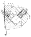
- a cylinder 1 of a rotary printing machine for receiving flexible plates 2 with bent ends 3, 4 with at least one narrow channel 8 which runs parallel to its axis of rotation and extends from a lateral surface 6 of the cylinder 1 into its interior 7.
- the plate 2 with a thickness d2, z. B. d2 0.3 mm, it is preferably printing plates, for. B. for planographic printing or letterpress printing (in particular flexographic printing, ie carrier plates with a plastic layer) or to carrier plates with z. B. rubber blankets attached to it.
- the leading end 3 and trailing end 4 each have a bent leg 9, 11.
- the channel 8 has approximately triangular cross-section.
- Channel 8 can too almost rectangular in cross section, in the form of a Slot 12, be formed (Fig. 4).
- At the The end of the channel 8 or slot 12 is parallel bore 16 in the cylinder 1 extending to the channel 8 appropriate.
- the channel 8 or slot 12 affects the Bore 16 in the form of a chord so that the bore 16 communicates with the channel 8 or slot 12.
- This wave 17 is in axial direction with several radially outwards acting, sprung pressure pieces 18 provided.
- the Thrust pieces 18 are fastened in the shaft 17 in such a way that whose pressure cam 19 over a lateral surface 21 of the shaft 17 can also act resiliently.
- the pressure cams 19 are cylindrical designed so that for each pressure cam 19th results, for example, in a line-shaped contact zone. It it is also possible, for example, to apply the pressure cams 18 to be provided with a ball end at its outer end.
- the channel 8 has a triangular design and is delimited to receive the leading end 3 of the plate 2 by a side surface 22 inclined by the opening angle alpha, while an opposite side surface 23 is directed perpendicular to the tangent 14, ie in the radial direction extends.
- a pressure medium supply 26 is arranged in this space 24, which is triangular in cross section and delimited by the two side surfaces 22, 23 and shaft 17. This room can also be closed on its end faces.
- This pressure medium supply 26 is designed, for example, as a tube 26 or hose with a circular cross section and is provided with a plurality of outlet openings 27 in the longitudinal direction.
- At least one end of the pressure medium supply 26 has a connection (not shown) for supplying a pressure medium, preferably compressed air.
- This connection can be permanently connected to a rotary transmitter, so that 1 pressure medium can be supplied to the channel 8 in any position of the cylinder.
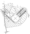
- This pressure medium supply 26, designed as a tube 26 can also be arranged in the shaft 17 (Fig. 2).
- This U-shaped groove 28 is arranged so that in the unclamped position Shaft 17, the outlet openings 27 of the tube 26 Pressure medium directly into channel 8.
- the pressure medium supply 26 can also be integrated in the shaft 17.
- the shaft 17 is provided with an axially extending bore 29, which is connected to outlet openings 31 opening into the channel 8.
- the pressure cams 19 can also be provided in the longitudinal direction with a bore 34 and with outlet openings 36 extending therefrom and pointing radially outwards. These holes 34 of the pressure cams 19 are connected to one another by means of a flexible tube, for example by means of a hose. It is also possible, in addition to or instead of the bores 29, 34, to arrange a pipe 38 with outlet openings 39 leading into the channel 8 in a recess 37 in a trailing side surface of the channel 8.
- the channel 8 rectangular cross-section and is therefore as Slot 12, which must also be closed on the front can, executed.
- the slot 8 is provided with a pressure medium supply.
- this can consist of one or two one or both end faces of the cylinder 1 arranged bores 33 exist on which a Pressure medium source is connected.
- the lower end 32 of the slot 8 too enlarge and use it, for example, with a tube 26 Outlet openings 27 corresponding to the first Insert embodiment.
- Outlet openings 41 to the outer surface 6 of the Cylinder 1 subsequently, d. H. for example rounded or chamfered transition area from the Shell surface 6 to the side surface 23 of the channel 8 arranged.
- the outlet openings 41 act on the Plate 2 in the area of the bending radius of the trailing folded end 4 of the plate 2.
- the outlet openings 41 are axial extending pressure medium supply 42 connected.
- a cylinder 1 in a cylinder 1 one Carries a plurality of plates 2 in the axial direction, to arrange several of these pressure medium feeds 26, each section of the channel 8 then For example, a plate 2 is assigned one own pressure medium supply 26 is assigned.
- the channel 8 is then preferably in the axial direction in divided individual sections so that individual rooms 24, i.e. Chambers are formed.
- the sum of the cross sections of all feed openings is to the sum of the cross sections of all openings from which False air can escape, adapted, preferably the supply openings are larger than the false air openings educated.
- An opening can escape from the false air can be, for example, the gap that is between the two legs 9, 11 of the plate 2 as a result of slightly larger width 8 of the channel 8 can result.
- the mode of operation of the device according to the invention is as follows:
- the pressure medium supply is assigned to the shaft 17, the outlet openings of the shaft 17 reach the area of the channel 8.
- the pressure medium supply 26 is now acted upon by pressure medium, as a result of which pressure medium enters channel 8 and a pressure is built up in channel 8.
- Channel 8 thus acts as a pressure chamber.
- the pressure medium acts on the folded end 4 of the plate and pushes the leg 11 of the trailing end 4 out of the channel 8.
- the trailing end 4 of the plate 2 is thus detached from the lateral surface 6 of the cylinder 1.
- Pressure medium is preferably supplied until the leg 11 is completely pushed out of the channel 8.
Landscapes
- Engineering & Computer Science (AREA)
- Mechanical Engineering (AREA)
- Supply, Installation And Extraction Of Printed Sheets Or Plates (AREA)
Applications Claiming Priority (2)
| Application Number | Priority Date | Filing Date | Title |
|---|---|---|---|
| DE19636412A DE19636412C1 (de) | 1996-09-07 | 1996-09-07 | Zylinder |
| DE19636412 | 1996-09-07 |
Publications (2)
| Publication Number | Publication Date |
|---|---|
| EP0827830A1 true EP0827830A1 (fr) | 1998-03-11 |
| EP0827830B1 EP0827830B1 (fr) | 2000-07-12 |
Family
ID=7804944
Family Applications (1)
| Application Number | Title | Priority Date | Filing Date |
|---|---|---|---|
| EP97114963A Expired - Lifetime EP0827830B1 (fr) | 1996-09-07 | 1997-08-29 | Cylindre |
Country Status (4)
| Country | Link |
|---|---|
| US (1) | US5842419A (fr) |
| EP (1) | EP0827830B1 (fr) |
| JP (1) | JP2996936B2 (fr) |
| DE (2) | DE19636412C1 (fr) |
Cited By (1)
| Publication number | Priority date | Publication date | Assignee | Title |
|---|---|---|---|---|
| EP0949072A1 (fr) * | 1998-04-09 | 1999-10-13 | MAN Roland Druckmaschinen AG | Cylindre d'impression |
Families Citing this family (15)
| Publication number | Priority date | Publication date | Assignee | Title |
|---|---|---|---|---|
| DE19729375A1 (de) * | 1997-07-09 | 1999-01-14 | Ltg Lufttechnische Gmbh | Vorrichtung zum Befestigen einer biegsamen Platte auf dem Umfang des Zylinders einer Lackiermaschine |
| DE19924784C2 (de) | 1999-05-29 | 2001-05-31 | Koenig & Bauer Ag | Vorrichtung zum Befestigen von biegsamen Platten auf einem Zylinder einer Rotationsdruckmaschine mit Drehrichtungsumkehr |
| DE10108745C1 (de) * | 2001-02-23 | 2002-05-23 | Koenig & Bauer Ag | Antrieb für eine Welle zum Klemmen und/oder Spannen von Aufzügen auf einem Zylinder |
| DE102004059338B3 (de) * | 2004-08-16 | 2005-12-22 | Koenig & Bauer Ag | Verfahren und Vorrichtung zum Abspannen mindestens eines Aufzugs von einem Zylinder einer Druckmaschine |
| US7618222B2 (en) * | 2006-03-01 | 2009-11-17 | Chi Hyun Kim | Collated fastener strips with opposing wire connectors |
| DE102006048093A1 (de) * | 2006-10-11 | 2008-04-17 | Koenig & Bauer Aktiengesellschaft | Rotationsdruckmaschine mit mindestens einem Druckwerk |
| DE102008002048B4 (de) * | 2008-05-28 | 2011-03-10 | Koenig & Bauer Aktiengesellschaft | Verwendung einer Reinigungsanlagen zum Reinigen einer oder mehrere Druckwerkszylinder einer Druckeinheit einer Druckmaschine |
| US8281716B2 (en) * | 2008-12-24 | 2012-10-09 | Printing Research, Inc. | Anti-marking jackets comprised of fluoropolymer and methods of using in offset printing |
| US8578853B2 (en) * | 2008-12-24 | 2013-11-12 | Printing Research, Inc. | Anti-marking jackets comprised of attachment structure and methods of using in offset printing |
| US8220388B2 (en) * | 2008-12-24 | 2012-07-17 | Printing Research, Inc. | Multiple layer anti-marking jackets and methods of using in offset printing |
| DE102009000511B4 (de) | 2009-01-30 | 2011-02-24 | Koenig & Bauer Aktiengesellschaft | Reinigungsanlage |
| US8424453B2 (en) | 2010-09-01 | 2013-04-23 | Printing Research, Inc. | Apparatus and method for adjusting anti-marking jackets |
| US8677899B2 (en) | 2011-01-31 | 2014-03-25 | Printing Research, Inc. | Reversible anti-marking jackets and methods of using |
| KR20120130517A (ko) * | 2011-05-23 | 2012-12-03 | 삼성디스플레이 주식회사 | 러빙 장치 |
| US9346258B2 (en) | 2012-05-02 | 2016-05-24 | Printing Research, Inc. | Method for cleaning anti-marking jackets |
Citations (4)
| Publication number | Priority date | Publication date | Assignee | Title |
|---|---|---|---|---|
| DE318702C (fr) * | ||||
| DE9320691U1 (de) * | 1993-11-30 | 1994-11-24 | Koenig & Bauer Ag | Formzylinder |
| DE4303381A1 (de) * | 1993-02-05 | 1994-12-01 | Roland Man Druckmasch | Plattenzylinder mit einer Einrichtung zum Anheben einer Druckplatte |
| EP0686503A1 (fr) * | 1994-06-08 | 1995-12-13 | S.A. Martin | Dispositif d'accrochage de clichés flexibles sur un cylindre d'impression |
Family Cites Families (8)
| Publication number | Priority date | Publication date | Assignee | Title |
|---|---|---|---|---|
| DE4203550C2 (de) * | 1992-02-07 | 1995-07-13 | Koenig & Bauer Ag | Drehzuführung für druckbeaufschlagbare Medien auf rotierbare Körper |
| US5335046A (en) * | 1993-02-22 | 1994-08-02 | Intergraph Corporation | Clamping mechanism for use on a rotatable plotter drum |
| DE4326251C2 (de) * | 1993-08-05 | 1997-08-28 | Koenig & Bauer Albert Ag | Gummi-/Drucktuchzylinder |
| DE4432817A1 (de) * | 1994-09-15 | 1996-03-21 | Roland Man Druckmasch | Formzylinder |
| DE19509561C2 (de) * | 1995-03-16 | 1997-10-23 | Koenig & Bauer Albert Ag | Vorrichtung zum Klemmen von Platten auf einem Zylinder |
| JP2952752B2 (ja) * | 1995-11-17 | 1999-09-27 | 株式会社東京機械製作所 | 刷版の版胴への固定および版胴からの解離装置 |
| DE29600845U1 (de) * | 1996-01-19 | 1996-03-07 | Roland Man Druckmasch | Vorrichtung zum Befestigen einer Bespannung auf einem Druckwerkzylinder |
| US5687647A (en) * | 1996-04-26 | 1997-11-18 | Heidelberger Druckmaschinen Ag | Plate cylinder with fixed tensioning plate mounting device |
-
1996
- 1996-09-07 DE DE19636412A patent/DE19636412C1/de not_active Revoked
-
1997
- 1997-08-29 DE DE59701999T patent/DE59701999D1/de not_active Expired - Fee Related
- 1997-08-29 EP EP97114963A patent/EP0827830B1/fr not_active Expired - Lifetime
- 1997-09-04 JP JP9239214A patent/JP2996936B2/ja not_active Expired - Fee Related
- 1997-09-05 US US08/924,085 patent/US5842419A/en not_active Expired - Fee Related
Patent Citations (4)
| Publication number | Priority date | Publication date | Assignee | Title |
|---|---|---|---|---|
| DE318702C (fr) * | ||||
| DE4303381A1 (de) * | 1993-02-05 | 1994-12-01 | Roland Man Druckmasch | Plattenzylinder mit einer Einrichtung zum Anheben einer Druckplatte |
| DE9320691U1 (de) * | 1993-11-30 | 1994-11-24 | Koenig & Bauer Ag | Formzylinder |
| EP0686503A1 (fr) * | 1994-06-08 | 1995-12-13 | S.A. Martin | Dispositif d'accrochage de clichés flexibles sur un cylindre d'impression |
Cited By (2)
| Publication number | Priority date | Publication date | Assignee | Title |
|---|---|---|---|---|
| EP0949072A1 (fr) * | 1998-04-09 | 1999-10-13 | MAN Roland Druckmaschinen AG | Cylindre d'impression |
| US6129018A (en) * | 1998-04-09 | 2000-10-10 | Man Roland Druckmaschinen Ag | Impression cylinder with a slot for receiving elastic molded ends of flexible plate |
Also Published As
| Publication number | Publication date |
|---|---|
| DE59701999D1 (de) | 2000-08-17 |
| EP0827830B1 (fr) | 2000-07-12 |
| US5842419A (en) | 1998-12-01 |
| DE19636412C1 (de) | 1998-01-08 |
| JPH1086335A (ja) | 1998-04-07 |
| JP2996936B2 (ja) | 2000-01-11 |
Similar Documents
| Publication | Publication Date | Title |
|---|---|---|
| DE19636412C1 (de) | Zylinder | |
| EP0085751B1 (fr) | Machine rotative d'impression offset de feuilles | |
| DE3723494C2 (de) | Spannvorrichtung | |
| DE19509561C2 (de) | Vorrichtung zum Klemmen von Platten auf einem Zylinder | |
| EP0070378B1 (fr) | Dispositif de fixation de l'élément intérieur d'un habillage double sur la surface d'un cylindre d'impression dans les machines d'impression | |
| DE4303381A1 (de) | Plattenzylinder mit einer Einrichtung zum Anheben einer Druckplatte | |
| EP0732202B1 (fr) | Cylindre avec un dispositif pour tendre une plaque d'impression | |
| CH691452A5 (de) | Vorrichtung zum Befestigen einer Gummitucheinheit auf einem Gummizylinder. | |
| EP0755785B1 (fr) | Dispositif de fixation d'une plaque avec réduction de la zône sans pression | |
| EP0930972A1 (fr) | Dispositif pour enlever des plaques | |
| EP0740609B1 (fr) | Dispositif de retenue d'un support courbe | |
| EP1268210B1 (fr) | Dispositif pour serrer et/ou bloquer des plaques souples | |
| DE19533178C2 (de) | Zylinder | |
| CH654524A5 (en) | Printing machine having a plurality of forme cylinders assigned to a central impression cylinder | |
| EP0732204B1 (fr) | Dispositif pour enlever une plaque d'impression d'un cylindre | |
| DD261770A1 (de) | Vorrichtung zum befestigen einer biegsamen druckplatte | |
| DE10255707A1 (de) | Rotationskörper einer Druckmaschine mit mindestens einem Hohlraum | |
| DE19524296C2 (de) | Zylinder | |
| DE2757552C2 (de) | Formzylinder für eine Rotationsdruckmaschine | |
| EP1567342B1 (fr) | Racle a reservoir d'encre | |
| DE19718549B4 (de) | Druckmaschine | |
| EP1990191A2 (fr) | Presse d'impression rotative pour bandes | |
| DE10306196B3 (de) | Farbübertragungswalze | |
| EP0995597A1 (fr) | Cylindre de plaque dans une machine d'impression avec dispositif de tension de plaque | |
| EP0579969B1 (fr) | Palier d'arbre pour machine d'usinage |
Legal Events
| Date | Code | Title | Description |
|---|---|---|---|
| PUAI | Public reference made under article 153(3) epc to a published international application that has entered the european phase |
Free format text: ORIGINAL CODE: 0009012 |
|
| AK | Designated contracting states |
Kind code of ref document: A1 Designated state(s): CH DE FR GB IT LI |
|
| 17P | Request for examination filed |
Effective date: 19980820 |
|
| AKX | Designation fees paid |
Free format text: CH DE FR GB IT LI |
|
| RBV | Designated contracting states (corrected) |
Designated state(s): CH DE FR GB IT LI |
|
| RAP1 | Party data changed (applicant data changed or rights of an application transferred) |
Owner name: KOENIG & BAUER AKTIENGESELLSCHAFT |
|
| 17Q | First examination report despatched |
Effective date: 19990316 |
|
| GRAG | Despatch of communication of intention to grant |
Free format text: ORIGINAL CODE: EPIDOS AGRA |
|
| GRAG | Despatch of communication of intention to grant |
Free format text: ORIGINAL CODE: EPIDOS AGRA |
|
| GRAG | Despatch of communication of intention to grant |
Free format text: ORIGINAL CODE: EPIDOS AGRA |
|
| GRAH | Despatch of communication of intention to grant a patent |
Free format text: ORIGINAL CODE: EPIDOS IGRA |
|
| GRAH | Despatch of communication of intention to grant a patent |
Free format text: ORIGINAL CODE: EPIDOS IGRA |
|
| GRAA | (expected) grant |
Free format text: ORIGINAL CODE: 0009210 |
|
| AK | Designated contracting states |
Kind code of ref document: B1 Designated state(s): CH DE FR GB IT LI |
|
| REG | Reference to a national code |
Ref country code: CH Ref legal event code: EP |
|
| ITF | It: translation for a ep patent filed |
Owner name: DE DOMINICIS & MAYER S.R.L. |
|
| REF | Corresponds to: |
Ref document number: 59701999 Country of ref document: DE Date of ref document: 20000817 |
|
| GBT | Gb: translation of ep patent filed (gb section 77(6)(a)/1977) |
Effective date: 20000728 |
|
| ET | Fr: translation filed | ||
| PLBE | No opposition filed within time limit |
Free format text: ORIGINAL CODE: 0009261 |
|
| STAA | Information on the status of an ep patent application or granted ep patent |
Free format text: STATUS: NO OPPOSITION FILED WITHIN TIME LIMIT |
|
| 26N | No opposition filed | ||
| REG | Reference to a national code |
Ref country code: GB Ref legal event code: IF02 |
|
| PGFP | Annual fee paid to national office [announced via postgrant information from national office to epo] |
Ref country code: FR Payment date: 20060720 Year of fee payment: 10 |
|
| PGFP | Annual fee paid to national office [announced via postgrant information from national office to epo] |
Ref country code: GB Payment date: 20060724 Year of fee payment: 10 Ref country code: CH Payment date: 20060724 Year of fee payment: 10 |
|
| PGFP | Annual fee paid to national office [announced via postgrant information from national office to epo] |
Ref country code: IT Payment date: 20060831 Year of fee payment: 10 |
|
| REG | Reference to a national code |
Ref country code: CH Ref legal event code: PL |
|
| GBPC | Gb: european patent ceased through non-payment of renewal fee |
Effective date: 20070829 |
|
| PG25 | Lapsed in a contracting state [announced via postgrant information from national office to epo] |
Ref country code: LI Free format text: LAPSE BECAUSE OF NON-PAYMENT OF DUE FEES Effective date: 20070831 Ref country code: CH Free format text: LAPSE BECAUSE OF NON-PAYMENT OF DUE FEES Effective date: 20070831 |
|
| REG | Reference to a national code |
Ref country code: FR Ref legal event code: ST Effective date: 20080430 |
|
| PG25 | Lapsed in a contracting state [announced via postgrant information from national office to epo] |
Ref country code: FR Free format text: LAPSE BECAUSE OF NON-PAYMENT OF DUE FEES Effective date: 20070831 |
|
| PG25 | Lapsed in a contracting state [announced via postgrant information from national office to epo] |
Ref country code: GB Free format text: LAPSE BECAUSE OF NON-PAYMENT OF DUE FEES Effective date: 20070829 |
|
| PGFP | Annual fee paid to national office [announced via postgrant information from national office to epo] |
Ref country code: DE Payment date: 20080929 Year of fee payment: 12 |
|
| PG25 | Lapsed in a contracting state [announced via postgrant information from national office to epo] |
Ref country code: IT Free format text: LAPSE BECAUSE OF NON-PAYMENT OF DUE FEES Effective date: 20070829 |
|
| PG25 | Lapsed in a contracting state [announced via postgrant information from national office to epo] |
Ref country code: DE Free format text: LAPSE BECAUSE OF NON-PAYMENT OF DUE FEES Effective date: 20100302 |