EP0827830A1 - Cylinder - Google Patents
Cylinder Download PDFInfo
- Publication number
- EP0827830A1 EP0827830A1 EP97114963A EP97114963A EP0827830A1 EP 0827830 A1 EP0827830 A1 EP 0827830A1 EP 97114963 A EP97114963 A EP 97114963A EP 97114963 A EP97114963 A EP 97114963A EP 0827830 A1 EP0827830 A1 EP 0827830A1
- Authority
- EP
- European Patent Office
- Prior art keywords
- cylinder
- plate
- channel
- pressure medium
- pressure
- Prior art date
- Legal status (The legal status is an assumption and is not a legal conclusion. Google has not performed a legal analysis and makes no representation as to the accuracy of the status listed.)
- Granted
Links
- 238000007639 printing Methods 0.000 claims description 6
- 238000000034 method Methods 0.000 claims description 4
- 210000002414 leg Anatomy 0.000 description 6
- 238000005553 drilling Methods 0.000 description 3
- 244000059549 Borneo rubber Species 0.000 description 1
- 238000005452 bending Methods 0.000 description 1
- 238000007644 letterpress printing Methods 0.000 description 1
- 230000007704 transition Effects 0.000 description 1
- 210000000689 upper leg Anatomy 0.000 description 1
Images


Classifications
-
- B—PERFORMING OPERATIONS; TRANSPORTING
- B41—PRINTING; LINING MACHINES; TYPEWRITERS; STAMPS
- B41F—PRINTING MACHINES OR PRESSES
- B41F13/00—Common details of rotary presses or machines
- B41F13/08—Cylinders
- B41F13/10—Forme cylinders
-
- B—PERFORMING OPERATIONS; TRANSPORTING
- B41—PRINTING; LINING MACHINES; TYPEWRITERS; STAMPS
- B41F—PRINTING MACHINES OR PRESSES
- B41F27/00—Devices for attaching printing elements or formes to supports
- B41F27/12—Devices for attaching printing elements or formes to supports for attaching flexible printing formes
- B41F27/1206—Feeding to or removing from the forme cylinder
-
- B—PERFORMING OPERATIONS; TRANSPORTING
- B41—PRINTING; LINING MACHINES; TYPEWRITERS; STAMPS
- B41P—INDEXING SCHEME RELATING TO PRINTING, LINING MACHINES, TYPEWRITERS, AND TO STAMPS
- B41P2227/00—Mounting or handling printing plates; Forming printing surfaces in situ
- B41P2227/60—Devices for transferring printing plates
- B41P2227/63—Devices for removing printing plates
Definitions
- the invention relates to a cylinder of a rotary printing press and a method of lifting a plate according to the preamble of claims 1 and 8.
- DE 43 03 381 A1 shows a plate cylinder with a device for lifting a pressure plate by means of compressed air.
- openings are provided in a lateral surface of the plate cylinder below the pressure plate to be lifted, which can be acted upon by compressed air.
- a disadvantage of this plate cylinder is that irregularities in the printed image can occur due to the openings arranged in the lateral surface or the pressure-free zone is enlarged.
- the invention has for its object a cylinder and to provide a method of lifting a panel.
- the cylinder according to the invention is in the drawing shown and is described in more detail below.
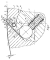
- a cylinder 1 of a rotary printing machine for receiving flexible plates 2 with bent ends 3, 4 with at least one narrow channel 8 which runs parallel to its axis of rotation and extends from a lateral surface 6 of the cylinder 1 into its interior 7.
- the plate 2 with a thickness d2, z. B. d2 0.3 mm, it is preferably printing plates, for. B. for planographic printing or letterpress printing (in particular flexographic printing, ie carrier plates with a plastic layer) or to carrier plates with z. B. rubber blankets attached to it.
- the leading end 3 and trailing end 4 each have a bent leg 9, 11.
- the channel 8 has approximately triangular cross-section.
- Channel 8 can too almost rectangular in cross section, in the form of a Slot 12, be formed (Fig. 4).
- At the The end of the channel 8 or slot 12 is parallel bore 16 in the cylinder 1 extending to the channel 8 appropriate.
- the channel 8 or slot 12 affects the Bore 16 in the form of a chord so that the bore 16 communicates with the channel 8 or slot 12.
- This wave 17 is in axial direction with several radially outwards acting, sprung pressure pieces 18 provided.
- the Thrust pieces 18 are fastened in the shaft 17 in such a way that whose pressure cam 19 over a lateral surface 21 of the shaft 17 can also act resiliently.
- the pressure cams 19 are cylindrical designed so that for each pressure cam 19th results, for example, in a line-shaped contact zone. It it is also possible, for example, to apply the pressure cams 18 to be provided with a ball end at its outer end.
- the channel 8 has a triangular design and is delimited to receive the leading end 3 of the plate 2 by a side surface 22 inclined by the opening angle alpha, while an opposite side surface 23 is directed perpendicular to the tangent 14, ie in the radial direction extends.
- a pressure medium supply 26 is arranged in this space 24, which is triangular in cross section and delimited by the two side surfaces 22, 23 and shaft 17. This room can also be closed on its end faces.
- This pressure medium supply 26 is designed, for example, as a tube 26 or hose with a circular cross section and is provided with a plurality of outlet openings 27 in the longitudinal direction.
- At least one end of the pressure medium supply 26 has a connection (not shown) for supplying a pressure medium, preferably compressed air.
- This connection can be permanently connected to a rotary transmitter, so that 1 pressure medium can be supplied to the channel 8 in any position of the cylinder.
- This pressure medium supply 26, designed as a tube 26 can also be arranged in the shaft 17 (Fig. 2).
- This U-shaped groove 28 is arranged so that in the unclamped position Shaft 17, the outlet openings 27 of the tube 26 Pressure medium directly into channel 8.
- the pressure medium supply 26 can also be integrated in the shaft 17.
- the shaft 17 is provided with an axially extending bore 29, which is connected to outlet openings 31 opening into the channel 8.
- the pressure cams 19 can also be provided in the longitudinal direction with a bore 34 and with outlet openings 36 extending therefrom and pointing radially outwards. These holes 34 of the pressure cams 19 are connected to one another by means of a flexible tube, for example by means of a hose. It is also possible, in addition to or instead of the bores 29, 34, to arrange a pipe 38 with outlet openings 39 leading into the channel 8 in a recess 37 in a trailing side surface of the channel 8.
- the channel 8 rectangular cross-section and is therefore as Slot 12, which must also be closed on the front can, executed.
- the slot 8 is provided with a pressure medium supply.
- this can consist of one or two one or both end faces of the cylinder 1 arranged bores 33 exist on which a Pressure medium source is connected.
- the lower end 32 of the slot 8 too enlarge and use it, for example, with a tube 26 Outlet openings 27 corresponding to the first Insert embodiment.
- Outlet openings 41 to the outer surface 6 of the Cylinder 1 subsequently, d. H. for example rounded or chamfered transition area from the Shell surface 6 to the side surface 23 of the channel 8 arranged.
- the outlet openings 41 act on the Plate 2 in the area of the bending radius of the trailing folded end 4 of the plate 2.
- the outlet openings 41 are axial extending pressure medium supply 42 connected.
- a cylinder 1 in a cylinder 1 one Carries a plurality of plates 2 in the axial direction, to arrange several of these pressure medium feeds 26, each section of the channel 8 then For example, a plate 2 is assigned one own pressure medium supply 26 is assigned.
- the channel 8 is then preferably in the axial direction in divided individual sections so that individual rooms 24, i.e. Chambers are formed.
- the sum of the cross sections of all feed openings is to the sum of the cross sections of all openings from which False air can escape, adapted, preferably the supply openings are larger than the false air openings educated.
- An opening can escape from the false air can be, for example, the gap that is between the two legs 9, 11 of the plate 2 as a result of slightly larger width 8 of the channel 8 can result.
- the mode of operation of the device according to the invention is as follows:
- the pressure medium supply is assigned to the shaft 17, the outlet openings of the shaft 17 reach the area of the channel 8.
- the pressure medium supply 26 is now acted upon by pressure medium, as a result of which pressure medium enters channel 8 and a pressure is built up in channel 8.
- Channel 8 thus acts as a pressure chamber.
- the pressure medium acts on the folded end 4 of the plate and pushes the leg 11 of the trailing end 4 out of the channel 8.
- the trailing end 4 of the plate 2 is thus detached from the lateral surface 6 of the cylinder 1.
- Pressure medium is preferably supplied until the leg 11 is completely pushed out of the channel 8.
Landscapes
- Engineering & Computer Science (AREA)
- Mechanical Engineering (AREA)
- Supply, Installation And Extraction Of Printed Sheets Or Plates (AREA)
Abstract
Bei einem eine Platte (2) aufnehmenden Zylinder (1) soll die Platte von einer Mantelfäche des Zylinders angehoben werden. Erfindungsgemäß wird dies durch Zuführung von Druckmittel in einen Enden der Platte aufnehmenden Kanal (8) des Zylinders erreicht. <IMAGE>In the case of a cylinder (1) receiving a plate (2), the plate is to be lifted from a surface of the cylinder. According to the invention, this is achieved by supplying pressure medium into one end of the plate-receiving channel (8) of the cylinder. <IMAGE>
Description
Die Erfindung betrifft einen Zylinder einer Rotationsdruckmaschine
und ein Verfahren zum Anheben einer Platte
gemäß dem Oberbegriff der Ansprüche 1 und 8.The invention relates to a cylinder of a rotary printing press
and a method of lifting a plate
according to the preamble of
Die DE 43 03 381 A1 zeigt einen Plattenzylinder mit
einer Einrichtung zum Anheben einer Druckplatte mittels
Druckluft. Dazu sind in einer Mantelfläche des
Plattenzylinders unterhalb der anzuhebenden Druckplatte
Öffnungen angebracht, die mit Druckluft beaufschlagbar
sind.
Nachteilig an diesem Plattenzylinder ist, daß durch die
in der Mantelfläche angeordneten Öffnungen
Unregelmäßigkeiten im Druckbild auftreten können bzw.
die druckfreie Zone vergrößert wird.DE 43 03 381 A1 shows a plate cylinder with a device for lifting a pressure plate by means of compressed air. For this purpose, openings are provided in a lateral surface of the plate cylinder below the pressure plate to be lifted, which can be acted upon by compressed air.
A disadvantage of this plate cylinder is that irregularities in the printed image can occur due to the openings arranged in the lateral surface or the pressure-free zone is enlarged.
Der Erfindung liegt die Aufgabe zugrunde, einen Zylinder und ein Verfahren zum Anheben einer Platte zu schaffen.The invention has for its object a cylinder and to provide a method of lifting a panel.
Diese Aufgabe wird erfindungsgemäß durch die Merkmale
des kennzeichnenden Teiles der Ansprüche 1 und 8 gelöst.This object is achieved by the features
of the characterizing part of
Die mit der Erfindung erzielbaren Vorteile bestehen insbesondere darin, daß durch die Anordnung von Druckmittelzuführungen im Kanal eine druckfreie Zone nicht vergrößert wird. The advantages that can be achieved with the invention exist especially in that by the arrangement of pressure medium supply in the channel pressure-free zone is not enlarged.
Während des Abhebevorganges vergrößern sich
Öffnungen aus denen beispielsweise Falschluft
entweichen kann nicht wesentlich, weshalb nur eine
minimale Menge von Druckmittel benötigt wird. Deshalb
können die Querschnitte der Leitungen zum Zuführen von
Druckmittel klein gehalten werden.
In vorteilhafter Weise kann ein Ende der Platte
vollständig aus dem Schlitz entfernt werden.
Zudem ist eine Zuführung des Druckmittels äußerst
einfach ausgeführt.During the lifting process, openings from which, for example, false air can escape do not enlarge significantly, which is why only a minimal amount of pressure medium is required. Therefore, the cross sections of the lines for supplying pressure medium can be kept small.
Advantageously, one end of the plate can be completely removed from the slot.
In addition, supply of the pressure medium is extremely simple.
Der erfindungsgemäße Zylinder ist in der Zeichnung dargestellt und wird im folgenden näher beschrieben.The cylinder according to the invention is in the drawing shown and is described in more detail below.
Es zeigen
- Fig. 1
- einen schematischen Schnitt durch einen Zylinder in einem ersten Ausführungsbeispiel;
- Fig. 2
- einen schematischen Schnitt durch den Zylinder in einem zweiten Ausführungsbeispiel;
- Fig. 3
- einen schematischen Schnitt durch den Zylinder in einem dritten Ausführungsbeispiel;
- Fig. 4
- einen schematischen Schnitt durch den Zylinder in einem vierten Ausführungsbeispiel;
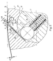
- Fig. 5
- einen schematischen Schnitt durch den Zylinder in einem fünften Ausführungsbeispiel.
- Fig. 1
- a schematic section through a cylinder in a first embodiment;
- Fig. 2
- a schematic section through the cylinder in a second embodiment;
- Fig. 3
- a schematic section through the cylinder in a third embodiment;
- Fig. 4
- a schematic section through the cylinder in a fourth embodiment;
- Fig. 5
- a schematic section through the cylinder in a fifth embodiment.
Ein Zylinder 1 einer Rotationsdruckmaschine ist zur
Aufnahme von biegsamen Platten 2 mit abgekanteten Enden
3, 4 mit mindestens einem parallel zu seiner Drehachse
verlaufenden, sich von einer Mantelfläche 6 des
Zylinders 1 in sein Inneres 7 erstreckenden, engen
Kanal 8 versehen.
Bei der Platte 2 mit einer Dicke d2, z. B. d2 = 0,3 mm,
handelt es sich vorzugsweise um Druckplatten, z. B. für
den Flachdruck oder Hochdruck (insbesondere Flexodruck,
d.h. Trägerplatten mit Kunststoffschicht) oder um
Trägerplatten mit z. B. darauf befestigten Gummitüchern.
Das vorlaufende Ende 3 und nachlaufende Ende 4 weisen
jeweils einen abgekanteten Schenkel 9, 11 auf.A cylinder 1 of a rotary printing machine is provided for receiving
In the
Im vorliegenden Beispiel weist der Kanal 8 annähernd
dreieckförmigen Querschnitt auf. Der Kanal 8 kann auch
im Querschnitt annähernd rechteckig, in Form eines
Schlitzes 12, ausgebildet sein (Fig. 4). Eine Breite b8
bzw. b12 des Querschnittes des Kanales 8 bzw. Schlitzes
12 weist an seinem Anfang 13 etwas mehr als die doppelte
Dicke d2 der Platte 2 auf, d.h. beispielsweise
b8 = 1 mm. Der Kanal 8 bzw. der Schlitz 12 ist bezüglich
einer an der Mantelfläche 6 im Bereich des Kanales 8
bzw. Schlitzes 9 anliegenden Tangente 14 um einen
Neigungswinkel Alpha, z. B. Alpha = 45°, geneigt. Am
Ende des Kanales 8 bzw. Schlitzes 12 ist eine parallel
zu dem Kanal 8 verlaufende Bohrung 16 in dem Zylinder 1
angebracht. Der Kanal 8 bzw. Schlitz 12 tangiert die
Bohrung 16 in Form einer Sehne, so daß die Bohrung 16
mit dem Kanal 8 bzw. Schlitz 12 in Verbindung steht. In
dieser Bohrung 16 ist ein Schwenkhebel 17, der im
vorliegenden Ausführungsbeispiel als eine Welle 17 mit
einem Radius r17, z. B. r17 = 15 mm, ausgeführt ist,
schwenkbar zentrisch gelagert. Diese Welle 17 ist in
axialer Richtung mit mehreren von radial nach außen
wirkenden, gefederten Druckstücken 18 versehen. Die
Druckstücke 18 sind so in der Welle 17 befestigt, daß
deren Drucknocken 19 über eine Mantelfläche 21 der Welle
17 hinaus federnd wirken können. Im dargestellten
Beispiel sind die Drucknocken 19 zylinderförmig
ausgestaltet, so daß sich für jeden Drucknocken 19
beispielsweise eine linienförmige Berührzone ergibt. Es
ist beispielsweise auch möglich, die Drucknocken 18 an
ihrem äußeren Ende mit einer Kugelkuppe zu versehen.In the present example, the
In einem ersten Ausführungsbeispiel ist der Kanal 8
dreieckförmig ausgeführt und wird zur Aufnahme des
vorlaufenden Endes 3 der Platte 2 von einer um den
Öffnungswinkel Alpha geneigten Seitenfläche 22 begrenzt,
während eine gegenüberliegende Seitenfläche 23 senkrecht
auf die Tangente 14 gerichtet ist, d.h. sich in radialer
Richtung erstreckt. In diesem von den beiden
Seitenflächen 22, 23 und Welle 17 begrenzten, im
Querschnitt dreieckförmigen Raum 24 ist eine
Druckmittelzuführung 26 angeordnet. Dieser Raum kann
auch noch zusätzlich an seinen Stirnseiten geschlossen
sein.
Diese Druckmittelzuführung 26 ist beispielsweise als
Rohr 26 oder Schlauch mit kreisförmigem Querschnitt
ausgeführt und ist in Längsrichtung mit einer Vielzahl
von Austrittsöffnungen 27 versehen. An mindestens einem
Ende der Druckmittelzuführung 26 ist ein
nichtdargestellter Anschluß zur Zufuhr eines
Druckmittels, vorzugsweise Druckluft, vorgesehen. Dieser
Anschluß kann permanent mit einem Drehübertrager
verbunden sein, so daß in jeder Stellung des Zylinders 1
Druckmittel dem Kanal 8 zugeführt werden kann. Es ist
aber auch möglich, die Druckmittelzuführung nur
zeitweise mit einer ortsfesten Druckmittelquelle zu
verbinden.In a first exemplary embodiment, the
This
Diese als Rohr 26 ausgebildete Druckmittelzuführung 26
kann auch in der Welle 17 angeordnet sein (Fig. 2). Dazu
weist die Welle 17 beispielsweise im Bereich ihrer
Mantelfläche 21 eine sich axial erstreckende, U-förmige
Nut 28 auf, die in radialer Richtung der Welle 17 weist
und nach außen offen ist. Diese U-förmige Nut 28 ist
derart angeordnet, daß in ungeklemmter Stellung der
Welle 17 die Austrittsöffnungen 27 des Rohres 26 das
Druckmittel direkt in den Kanal 8 münden. Die
Druckstücke 18 und die U-förmige Nut schließen deshalb
beispielsweise einen Öffnungswinkel Beta, z. B.
Beta = 35° ein.This
Die Druckmittelzuführung 26 kann - wie in einem dritten
Ausführungsbeispiel (Fig. 3) angedeutet - auch in der
Welle 17 integriert sein. Dazu ist beispielsweise die
Welle 17 mit einer sich axial erstreckenden Bohrung 29
versehen, die mit in den Kanal 8 mündenden
Austrittsöffnungen 31 verbunden ist.
Zusätzlich oder anstelle der in der Welle 17
integrierten Bohrung 29 können auch die Drucknocken 19
in Längsrichtung mit einer Bohrung 34 und mit von dieser
ausgehenden, radial nach außen weisenden
Austrittsöffnungen 36 versehen sein. Diese Bohrungen 34
der Drucknocken 19 sind untereinander mittels eines
flexiblen Rohres beispielsweise mittels eines Schlauches
verbunden.
Auch ist es möglich, zusätzlich oder anstelle der
Bohrungen 29, 34 in einer Aussparung 37 einer
nachlaufenden Seitenfläche des Kanals 8 ein Rohr 38 mit
in den Kanal 8 führenden Austrittsöffnungen 39
anzuordnen.As indicated in a third exemplary embodiment (FIG. 3), the
In addition to or instead of the
It is also possible, in addition to or instead of the
In einem vierten Ausführungsbeispiel weist der Kanal 8
rechteckförmigen Querschnitt auf und ist somit als
Schlitz 12, der zusätzlich stirnseitig geschlossen sein
kann, ausgeführt. An seinem innen liegenden Ende 32 ist
der Schlitz 8 mit einer Druckmittelzuführung versehen.
Diese kann im einfachsten Fall aus einer oder zwei an
einer oder beiden Stirnflächen des Zylinders 1
angeordneten Bohrungen 33 bestehen, an denen eine
Druckmittelquelle angeschlossen wird. Es ist aber auch
möglich, das untere Ende 32 des Schlitzes 8 zu
vergrößern und daran beispielsweise ein Rohr 26 mit
Austrittsöffnungen 27 entsprechend dem ersten
Ausführungsbeispiel einzulegen. In a fourth exemplary embodiment, the
In einem fünften Ausführungsbeispiel sind
Austrittsöffnungen 41 an die Mantelfläche 6 des
Zylinders 1 anschließend, d. h. im beispielsweise
abgerundeten oder angefasten Übergangsbereich von der
Mantelfläche 6 zu der Seitenfläche 23 des Kanals 8
angeordnet. Die Austrittsöffnungen 41 wirken auf die
Platte 2 im Bereich des Biegeradius des nachlaufenden,
abgekanteten Endes 4 der Platte 2.In a fifth
Die Austrittsöffnungen 41 sind mit einer axial
verlaufenden Druckmittelzuführung 42 verbunden. The
Es ist auch möglich, z. B. bei einem Zylinder 1 der eine
Mehrzahl von Platten 2 in axialer Richtung trägt,
mehrere dieser Druckmittelzuführungen 26 anzuordnet,
wobei dann jedem Abschnitt des Kanals 8 der
beispielsweise einer Platte 2 zugeordnet ist, eine
eigene Druckmittelzuführung 26 zugeordnet ist.
Vorzugsweise ist der Kanal 8 dann in axialer Richtung in
einzelne Abschnitte unterteilt, so daß einzelne Räume
24, d.h. Kammern gebildet werden.It is also possible e.g. B. in a cylinder 1 one
Carries a plurality of
Eine Summe der Querschnitte aller Zuführöffnungen ist
auf die Summe der Querschnitte aller Öffnungen aus denen
Falschluft entweichen kann, angepaßt, vorzugsweise sind
die Zuführöffnungen größer als die Falschluftöffnungen
ausgebildet. Eine Öffnung aus der Falschluft entweichen
kann, ist beispielsweise der Spalt, der sich zwischen
den beiden Schenkeln 9, 11 der Platte 2 infolge der
etwas größeren Breite 8 des Kanales 8 ergeben kann.The sum of the cross sections of all feed openings is
to the sum of the cross sections of all openings from which
False air can escape, adapted, preferably
the supply openings are larger than the false air openings
educated. An opening can escape from the false air
can be, for example, the gap that is between
the two
Die Funktionsweise der erfindungsgemäßen Vorrichtung ist folgendermaßen:The mode of operation of the device according to the invention is as follows:
Zum Entfernen der Platte 2 wird die Welle 17 von ihrer
Klemmstellung in ihre Lösestellung im Uhrzeigersinn
geschwenkt , worauf die Drucknocken 19 die Schenkel 9,
11 der Enden 3, 4 freigeben. Die Drucknocken 19 werden
in die Bohrung 16 geführt, in der sich die Drucknocken
17 an der Mantelfläche der Bohrung 16 abstützen. To remove the
Ist die Druckmittelzuführung der Welle 17 zugeordnet,
gelangen die Austrittsöffnungen der Welle 17 in den
Bereich des Kanales 8.
Die Druckmittelzuführung 26 wird nun mit Druckmittel
beaufschlagt, wodurch in den Kanal 8 Druckmittel gelangt
und in dem Kanal 8 ein Druck aufgebaut wird. Somit wirkt
der Kanal 8 als Druckkammer. Das Druckmittel wirkt auf
das abgekantete Ende 4 der Platte und schiebt den
Schenkel 11 des nachlaufenden Endes 4 aus dem Kanal 8.
Das nachlaufende Ende 4 der Platte 2 wird somit von der
Mantelfläche 6 des Zylinders 1 gelöst. Vorzugsweise wird
solange Druckmittel zugeführt bis der Schenkel 11
vollständig aus dem Kanal 8 herausgeschoben ist. If the pressure medium supply is assigned to the
The pressure
- 11
- Zylindercylinder
- 22nd
- Platteplate
- 33rd
- Ende, vorlaufendEnd, leading
- 44th
- Ende, nachlaufendEnd, trailing
- 55
- --
- 66
- Mantelfläche (1)Lateral surface (1)
- 77
- Inneres (1)Interior (1)
- 88th
- Kanalchannel
- 99
- Schenkel (3)Thigh (3)
- 1010th
- --
- 1111
- Schenkel (4)leg (4)
- 1212th
- Schlitzslot
- 1313
- Anfang (8; 12)Beginning (8; 12)
- 1414
- Tangentetangent
- 1515
- --
- 1616
- Bohrungdrilling
- 1717th
- Wellewave
- 1818th
- DruckstückPressure piece
- 1919th
- DrucknockenPressure cams
- 2020th
- --
- 2121
- MantelflächeLateral surface
- 2222
- Seitenfläche (8)Side (8)
- 2323
- Seitenfläche (8)Side (8)
- 2424th
- Raumroom
- 2525th
- --
- 2626
- Druckmittelzuführung, RohrPressure medium supply, pipe
- 2727
- Austrittsöffnung (26) Outlet (26)
- 2828
- Nut (17)Groove (17)
- 2929
- Bohrungdrilling
- 3030th
- --
- 3131
- AustrittsöffnungOutlet opening
- 3232
- Ende (12)End (12)
- 3333
- Bohrungdrilling
- 3434
- Bohrung (19)Bore (19)
- 3535
- --
- 3636
- Austrittsöffnung (34)Outlet opening (34)
- 3737
- AussparungRecess
- 3838
- Rohrpipe
- 3939
- Austrittsöffnung (38)Outlet (38)
- 4040
- --
- 4141
- Austrittsöffnung (38)Outlet opening (38)
- 4242
- DruckmittelzuführungPressure medium supply
- b8b8
- Breite des Kanals (8)Channel Width (8)
- d2d2
- Dicke der Platte (2)Plate thickness (2)
- Alphaalpha
- NeigungswinkelAngle of inclination
- Betabeta
- ÖffnungswinkelOpening angle
Claims (8)
Applications Claiming Priority (2)
| Application Number | Priority Date | Filing Date | Title |
|---|---|---|---|
| DE19636412A DE19636412C1 (en) | 1996-09-07 | 1996-09-07 | Cylinder of rotary printer with outlets |
| DE19636412 | 1996-09-07 |
Publications (2)
| Publication Number | Publication Date |
|---|---|
| EP0827830A1 true EP0827830A1 (en) | 1998-03-11 |
| EP0827830B1 EP0827830B1 (en) | 2000-07-12 |
Family
ID=7804944
Family Applications (1)
| Application Number | Title | Priority Date | Filing Date |
|---|---|---|---|
| EP97114963A Expired - Lifetime EP0827830B1 (en) | 1996-09-07 | 1997-08-29 | Cylinder |
Country Status (4)
| Country | Link |
|---|---|
| US (1) | US5842419A (en) |
| EP (1) | EP0827830B1 (en) |
| JP (1) | JP2996936B2 (en) |
| DE (2) | DE19636412C1 (en) |
Cited By (1)
| Publication number | Priority date | Publication date | Assignee | Title |
|---|---|---|---|---|
| EP0949072A1 (en) * | 1998-04-09 | 1999-10-13 | MAN Roland Druckmaschinen AG | Printing cylinder |
Families Citing this family (15)
| Publication number | Priority date | Publication date | Assignee | Title |
|---|---|---|---|---|
| DE19729375A1 (en) * | 1997-07-09 | 1999-01-14 | Ltg Lufttechnische Gmbh | Device for fastening a flexible plate on the circumference of the cylinder of a painting machine |
| DE19924784C2 (en) | 1999-05-29 | 2001-05-31 | Koenig & Bauer Ag | Device for fastening flexible plates on a cylinder of a rotary printing machine with reversal of the direction of rotation |
| DE10108745C1 (en) * | 2001-02-23 | 2002-05-23 | Koenig & Bauer Ag | Drive, for shaft to clamp or tension hoists on cylinder, has boring in cylinder for third shaft |
| DE102004059338B3 (en) * | 2004-08-16 | 2005-12-22 | Koenig & Bauer Ag | Releasing process for tympan on printing press cylinder involves blowing compressed air at one end of tympan onto both its endfaces |
| US7618222B2 (en) * | 2006-03-01 | 2009-11-17 | Chi Hyun Kim | Collated fastener strips with opposing wire connectors |
| DE102006048093A1 (en) * | 2006-10-11 | 2008-04-17 | Koenig & Bauer Aktiengesellschaft | Rotary printing press i.e. sheet feed-offset rotary printing press, has generating unit to generate air stream that acts on moisture applying roller, where unit is attached to plate cylinder, such that stream is generated in channel |
| DE102008002048B4 (en) * | 2008-05-28 | 2011-03-10 | Koenig & Bauer Aktiengesellschaft | Use of a cleaning system for cleaning one or more printing cylinder of a printing unit of a printing press |
| US8578853B2 (en) * | 2008-12-24 | 2013-11-12 | Printing Research, Inc. | Anti-marking jackets comprised of attachment structure and methods of using in offset printing |
| US8220388B2 (en) * | 2008-12-24 | 2012-07-17 | Printing Research, Inc. | Multiple layer anti-marking jackets and methods of using in offset printing |
| US8281716B2 (en) * | 2008-12-24 | 2012-10-09 | Printing Research, Inc. | Anti-marking jackets comprised of fluoropolymer and methods of using in offset printing |
| DE102009000511B4 (en) | 2009-01-30 | 2011-02-24 | Koenig & Bauer Aktiengesellschaft | purifier |
| US8424453B2 (en) | 2010-09-01 | 2013-04-23 | Printing Research, Inc. | Apparatus and method for adjusting anti-marking jackets |
| US8677899B2 (en) | 2011-01-31 | 2014-03-25 | Printing Research, Inc. | Reversible anti-marking jackets and methods of using |
| KR20120130517A (en) * | 2011-05-23 | 2012-12-03 | 삼성디스플레이 주식회사 | Rubbing apparatus |
| US9346258B2 (en) | 2012-05-02 | 2016-05-24 | Printing Research, Inc. | Method for cleaning anti-marking jackets |
Citations (4)
| Publication number | Priority date | Publication date | Assignee | Title |
|---|---|---|---|---|
| DE318702C (en) * | ||||
| DE9320691U1 (en) * | 1993-11-30 | 1994-11-24 | Koenig & Bauer Ag | Forme cylinder |
| DE4303381A1 (en) * | 1993-02-05 | 1994-12-01 | Roland Man Druckmasch | Plate cylinder with a device for lifting a printing plate |
| EP0686503A1 (en) * | 1994-06-08 | 1995-12-13 | S.A. Martin | Fastening device for flexible printing plates on a printing cylinder |
Family Cites Families (8)
| Publication number | Priority date | Publication date | Assignee | Title |
|---|---|---|---|---|
| DE4203550C2 (en) * | 1992-02-07 | 1995-07-13 | Koenig & Bauer Ag | Rotary feed for pressurizable media on rotatable bodies |
| US5335046A (en) * | 1993-02-22 | 1994-08-02 | Intergraph Corporation | Clamping mechanism for use on a rotatable plotter drum |
| DE4326251C2 (en) * | 1993-08-05 | 1997-08-28 | Koenig & Bauer Albert Ag | Rubber / blanket cylinder |
| DE4432817A1 (en) * | 1994-09-15 | 1996-03-21 | Roland Man Druckmasch | Shaping cylinder for rotation printing machine |
| DE19509561C2 (en) * | 1995-03-16 | 1997-10-23 | Koenig & Bauer Albert Ag | Device for clamping plates on a cylinder |
| JP2952752B2 (en) * | 1995-11-17 | 1999-09-27 | 株式会社東京機械製作所 | Device for fixing plate to plate cylinder and releasing from plate cylinder |
| DE29600845U1 (en) * | 1996-01-19 | 1996-03-07 | Roland Man Druckmasch | Device for fastening a covering on a printing unit cylinder |
| US5687647A (en) * | 1996-04-26 | 1997-11-18 | Heidelberger Druckmaschinen Ag | Plate cylinder with fixed tensioning plate mounting device |
-
1996
- 1996-09-07 DE DE19636412A patent/DE19636412C1/en not_active Revoked
-
1997
- 1997-08-29 DE DE59701999T patent/DE59701999D1/en not_active Expired - Fee Related
- 1997-08-29 EP EP97114963A patent/EP0827830B1/en not_active Expired - Lifetime
- 1997-09-04 JP JP9239214A patent/JP2996936B2/en not_active Expired - Fee Related
- 1997-09-05 US US08/924,085 patent/US5842419A/en not_active Expired - Fee Related
Patent Citations (4)
| Publication number | Priority date | Publication date | Assignee | Title |
|---|---|---|---|---|
| DE318702C (en) * | ||||
| DE4303381A1 (en) * | 1993-02-05 | 1994-12-01 | Roland Man Druckmasch | Plate cylinder with a device for lifting a printing plate |
| DE9320691U1 (en) * | 1993-11-30 | 1994-11-24 | Koenig & Bauer Ag | Forme cylinder |
| EP0686503A1 (en) * | 1994-06-08 | 1995-12-13 | S.A. Martin | Fastening device for flexible printing plates on a printing cylinder |
Cited By (2)
| Publication number | Priority date | Publication date | Assignee | Title |
|---|---|---|---|---|
| EP0949072A1 (en) * | 1998-04-09 | 1999-10-13 | MAN Roland Druckmaschinen AG | Printing cylinder |
| US6129018A (en) * | 1998-04-09 | 2000-10-10 | Man Roland Druckmaschinen Ag | Impression cylinder with a slot for receiving elastic molded ends of flexible plate |
Also Published As
| Publication number | Publication date |
|---|---|
| JP2996936B2 (en) | 2000-01-11 |
| DE59701999D1 (en) | 2000-08-17 |
| JPH1086335A (en) | 1998-04-07 |
| US5842419A (en) | 1998-12-01 |
| EP0827830B1 (en) | 2000-07-12 |
| DE19636412C1 (en) | 1998-01-08 |
Similar Documents
| Publication | Publication Date | Title |
|---|---|---|
| DE19636412C1 (en) | Cylinder of rotary printer with outlets | |
| EP0085751B1 (en) | Rotary machine for offset printing on sheets | |
| DE3723494C2 (en) | Jig | |
| DE19509561C2 (en) | Device for clamping plates on a cylinder | |
| EP0070378B1 (en) | Device for fixing the lower cover of a double-layered covering to the cylinder surface of a printing cylinder in printing machines | |
| DE4303381A1 (en) | Plate cylinder with a device for lifting a printing plate | |
| EP0732202B1 (en) | Cylinder with a device for tensioning a printing plate | |
| CH691452A5 (en) | Device for attaching a blanket unit on a blanket cylinder. | |
| EP0755785B1 (en) | Device for attaching printing plates with means for reducing pressure-free zone | |
| EP0740609B1 (en) | Arrangement for retaining a curved support | |
| EP1268210B1 (en) | Device for clamping and/or jamming flexible plates | |
| DE19533178C2 (en) | cylinder | |
| CH654524A5 (en) | Printing machine having a plurality of forme cylinders assigned to a central impression cylinder | |
| EP0732204B1 (en) | Device for disengaging a printing plate from a cylinder | |
| DD261770A1 (en) | DEVICE FOR FIXING A BENDING PRESSURE PLATE | |
| DE10255707A1 (en) | Rotary body for printer, has hollow cavity with fitted profiled body holding functional device | |
| DE19524296C2 (en) | cylinder | |
| DE2757552C2 (en) | Form cylinder for a rotary printing press | |
| EP1567342B1 (en) | Ink reservoir doctor blade | |
| DE19718549B4 (en) | press | |
| EP1990191A2 (en) | Web-fed printing press | |
| DE10306196B3 (en) | Ink transfer roller | |
| EP0995597A1 (en) | Plate cylinder of a printing press with plate tensioning device | |
| EP0579969B1 (en) | Shaft bearing for processing machine | |
| AT212855B (en) | Round forme cylinders for printing machines |
Legal Events
| Date | Code | Title | Description |
|---|---|---|---|
| PUAI | Public reference made under article 153(3) epc to a published international application that has entered the european phase |
Free format text: ORIGINAL CODE: 0009012 |
|
| AK | Designated contracting states |
Kind code of ref document: A1 Designated state(s): CH DE FR GB IT LI |
|
| 17P | Request for examination filed |
Effective date: 19980820 |
|
| AKX | Designation fees paid |
Free format text: CH DE FR GB IT LI |
|
| RBV | Designated contracting states (corrected) |
Designated state(s): CH DE FR GB IT LI |
|
| RAP1 | Party data changed (applicant data changed or rights of an application transferred) |
Owner name: KOENIG & BAUER AKTIENGESELLSCHAFT |
|
| 17Q | First examination report despatched |
Effective date: 19990316 |
|
| GRAG | Despatch of communication of intention to grant |
Free format text: ORIGINAL CODE: EPIDOS AGRA |
|
| GRAG | Despatch of communication of intention to grant |
Free format text: ORIGINAL CODE: EPIDOS AGRA |
|
| GRAG | Despatch of communication of intention to grant |
Free format text: ORIGINAL CODE: EPIDOS AGRA |
|
| GRAH | Despatch of communication of intention to grant a patent |
Free format text: ORIGINAL CODE: EPIDOS IGRA |
|
| GRAH | Despatch of communication of intention to grant a patent |
Free format text: ORIGINAL CODE: EPIDOS IGRA |
|
| GRAA | (expected) grant |
Free format text: ORIGINAL CODE: 0009210 |
|
| AK | Designated contracting states |
Kind code of ref document: B1 Designated state(s): CH DE FR GB IT LI |
|
| REG | Reference to a national code |
Ref country code: CH Ref legal event code: EP |
|
| ITF | It: translation for a ep patent filed |
Owner name: DE DOMINICIS & MAYER S.R.L. |
|
| REF | Corresponds to: |
Ref document number: 59701999 Country of ref document: DE Date of ref document: 20000817 |
|
| GBT | Gb: translation of ep patent filed (gb section 77(6)(a)/1977) |
Effective date: 20000728 |
|
| ET | Fr: translation filed | ||
| PLBE | No opposition filed within time limit |
Free format text: ORIGINAL CODE: 0009261 |
|
| STAA | Information on the status of an ep patent application or granted ep patent |
Free format text: STATUS: NO OPPOSITION FILED WITHIN TIME LIMIT |
|
| 26N | No opposition filed | ||
| REG | Reference to a national code |
Ref country code: GB Ref legal event code: IF02 |
|
| PGFP | Annual fee paid to national office [announced via postgrant information from national office to epo] |
Ref country code: FR Payment date: 20060720 Year of fee payment: 10 |
|
| PGFP | Annual fee paid to national office [announced via postgrant information from national office to epo] |
Ref country code: GB Payment date: 20060724 Year of fee payment: 10 Ref country code: CH Payment date: 20060724 Year of fee payment: 10 |
|
| PGFP | Annual fee paid to national office [announced via postgrant information from national office to epo] |
Ref country code: IT Payment date: 20060831 Year of fee payment: 10 |
|
| REG | Reference to a national code |
Ref country code: CH Ref legal event code: PL |
|
| GBPC | Gb: european patent ceased through non-payment of renewal fee |
Effective date: 20070829 |
|
| PG25 | Lapsed in a contracting state [announced via postgrant information from national office to epo] |
Ref country code: LI Free format text: LAPSE BECAUSE OF NON-PAYMENT OF DUE FEES Effective date: 20070831 Ref country code: CH Free format text: LAPSE BECAUSE OF NON-PAYMENT OF DUE FEES Effective date: 20070831 |
|
| REG | Reference to a national code |
Ref country code: FR Ref legal event code: ST Effective date: 20080430 |
|
| PG25 | Lapsed in a contracting state [announced via postgrant information from national office to epo] |
Ref country code: FR Free format text: LAPSE BECAUSE OF NON-PAYMENT OF DUE FEES Effective date: 20070831 |
|
| PG25 | Lapsed in a contracting state [announced via postgrant information from national office to epo] |
Ref country code: GB Free format text: LAPSE BECAUSE OF NON-PAYMENT OF DUE FEES Effective date: 20070829 |
|
| PGFP | Annual fee paid to national office [announced via postgrant information from national office to epo] |
Ref country code: DE Payment date: 20080929 Year of fee payment: 12 |
|
| PG25 | Lapsed in a contracting state [announced via postgrant information from national office to epo] |
Ref country code: IT Free format text: LAPSE BECAUSE OF NON-PAYMENT OF DUE FEES Effective date: 20070829 |
|
| PG25 | Lapsed in a contracting state [announced via postgrant information from national office to epo] |
Ref country code: DE Free format text: LAPSE BECAUSE OF NON-PAYMENT OF DUE FEES Effective date: 20100302 |