EP1567342B1 - Ink reservoir doctor blade - Google Patents
Ink reservoir doctor blade Download PDFInfo
- Publication number
- EP1567342B1 EP1567342B1 EP03775395A EP03775395A EP1567342B1 EP 1567342 B1 EP1567342 B1 EP 1567342B1 EP 03775395 A EP03775395 A EP 03775395A EP 03775395 A EP03775395 A EP 03775395A EP 1567342 B1 EP1567342 B1 EP 1567342B1
- Authority
- EP
- European Patent Office
- Prior art keywords
- doctor blade
- clamping plate
- rod
- fasteners
- roller
- Prior art date
- Legal status (The legal status is an assumption and is not a legal conclusion. Google has not performed a legal analysis and makes no representation as to the accuracy of the status listed.)
- Expired - Lifetime
Links
- 230000000694 effects Effects 0.000 description 3
- 239000003973 paint Substances 0.000 description 3
- 238000005452 bending Methods 0.000 description 2
- 239000002655 kraft paper Substances 0.000 description 2
- 210000003739 neck Anatomy 0.000 description 2
- 238000005553 drilling Methods 0.000 description 1
- 239000012535 impurity Substances 0.000 description 1
- 238000004519 manufacturing process Methods 0.000 description 1
- 230000002093 peripheral effect Effects 0.000 description 1
Images

Classifications
-
- B—PERFORMING OPERATIONS; TRANSPORTING
- B41—PRINTING; LINING MACHINES; TYPEWRITERS; STAMPS
- B41F—PRINTING MACHINES OR PRESSES
- B41F31/00—Inking arrangements or devices
- B41F31/02—Ducts, containers, supply or metering devices
- B41F31/027—Ink rail devices for inking ink rollers
Definitions
- the WO 0078548 A1 shows a clamping device for a doctor blade, wherein a clamping rail has been provided with a T-shaped groove, so that this, in operative connection with the spring of the carrier, the doctor blade can clamp.
- the clamping plates are flexible plates which are held on the doctoring chamber body by screws or similar fixing means, but are not finally fixed. Clamping takes place on the side of the screws facing the roller, in that the fastening means elongated in the axial direction (z) of the roller exert a force on the clamping plate which points away from the doctor chamber body.
- the clamping plate is held by the screws on the doctoring chamber body so that the clamping plate bends and on the side of the screws facing the roller exerts a force on the doctor blade which is directed onto the doctoring chamber body and fixes the doctor blade to the doctoring chamber body. If the force exerted by the elongated fastener force effect is suppressed, no force is exerted on the doctor blade and possibly the clamping plate.
- the fastening means which are elongate in the axial direction (z) of the roller are rods with a partially round cross section, which are rotatably mounted in the doctor chamber body.
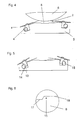
- the FIG. 1 shows a paint chamber doctor blade 1 of the prior art.
- the ink chamber 8 is limited by the inking roller 6 of the doctoring chamber body 5, which of course may also consist of several parts, and the doctor blade 2 is limited.
- the two doctor blades 2 of the ink chamber doctor blade 1 are each fixed by a clamping plate 3 which presses the doctor blade associated with it against the doctor chamber body 5.
- the force required for this purpose is the restoring force of the clamping plate, which arises because the clamping plate between the elongated fastening element 4, which is pronounced in the present case as a rod and the head of the screw 7 and the doctor chamber body 5 is bent.
- FIG. 3 shows a clamping plate, which for use in the in the Figures 1 and 2 illustrated doctoring chamber is suitable.
- the round holes 10 and the grooves 11 form the apertures 9.
- the diameter of the holes 10 is matched with the necessary play on the head of the screw 7, while the width of the groove 11 is tuned to the diameter of the screw neck.
- FIG. 4 and 5 show a chamber doctor blade according to the invention, in which the clamping plates 3 is provided with an attachment piece 13 which comprises a connecting element 14.
- the connecting element is matched to the recess 15 of the rod 4.
- the shape of the recess 15 is in FIG. 6 shown again.
- FIG. 6 shows a plan view of the clamping plate 3, which in the in FIGS. 4 and 5 used chambered doctor blade according to the invention is used.
Abstract
Description
Die Erfindung betrifft ein Farbkammerrakel nach dem Oberbegriff des Anspruchs 1.
Farbkammerrakel sind seit langem bekannt. Die Rakelmesser von Farbkammerrakeln unterliegen ständigem Verschleiß und müssen daher regelmäßig gewechselt werden. Die Rakelmesser werden in der Regel zu ihrer Fixierung von einem Klemmblech gegen den Rakelkammerkörper gedrückt. In der Vergangenheit wurde das Klemmblech zu diesem Zweck mit Schrauben an dem RakelkammerKörper befestigt, wie es in der
In jüngerer Zeit ist festzustellen, dass die vorgenannten Arten der Befestigung des Klemmblechs beziehungsweise des Rakelmessers am Rakelkammerkörper dadurch ersetzt wird, dass
- das Klemmblech in Wirkverbindung mit in der axialen Richtung der Walze langgestreckten Befestigungsmitteln steht,
- welche im wesentlichen parallel zu dem Klemmblech angeordnet sind
- und von welchen die zur Fixierung des zumindest einen Rakelmessers notwendige Kraft aufgebracht wird,
Farbkammerrakel have long been known. The doctor blades of Farbkammerrakeln are subject to constant wear and must therefore be changed regularly. The doctor blades are usually pressed to their fixation of a clamping plate against the Rakelkammerkörper. In the past, the clamping plate was fastened for this purpose with screws to the doctor chamber body, as in the
More recently, it has been found that the aforementioned types of attachment of the clamping plate or the doctor blade to the doctor chamber body is replaced by
- the clamping plate is in operative connection with fastening means elongated in the axial direction of the roller,
- which are arranged substantially parallel to the clamping plate
- and from which the force necessary for fixing the at least one doctor blade is applied,
Die
Bei den Klemmblechen handelt es sich um biegsame Bleche, die durch Schrauben oder ähnliche Fixierungsmittel am Rakelkammerkörper gehalten, jedoch nicht endgültig fixiert sind. Auf der der Walze zugewandten Seite der Schrauben erfolgt die Verklemmung, indem die in der axialen Richtung (z) der Walze langgestreckten Befestigungsmittel eine Kraft auf das Klemmblech ausüben, welche von dem Rakelkammerkörper wegzeigt. Das Klemmblech wird jedoch von den Schrauben an dem Rakelkammerkörper gehalten, so dass sich das Klemmblech verbiegt und auf der der Walze zugewandten Seite der Schrauben eine Kraft auf das Rakelmesser ausübt, welche auf den Rakelkammerkörper gerichtet ist und das Rakelmesser am Rakelkammerkörper fixiert. Wenn die von dem langgestreckten Befestigungsmittel ausgeübte Kraftwirkung unterbunden wird, wird auch keine Kraft mehr auf das Rakelmesser und gegebenenfalls das Klemmblech ausgeübt.
In der Regel handelt es sich bei den in der axialen Richtung (z) der Walze langgestreckten Befestigungsmitteln um Stangen mit einem teilweise runden Querschnitt, welche in dem Rakelkammerkörper drehbar gelagert sind. Solche Stangen sind dann mit einer Ausnehmung oder einem Vorsprung versehen, was dazu führt, dass bei einer Drehung der Stange eine Kraft ausgeübt wird, deren Resultierende von der Rakelkammer weg zeigt. Es ist jedoch auch denkbar, an dieser Stelle einen aufblasbaren Schlauch oder einen anderen Körper zu platzieren, welcher sein Volumen vergrößern kann und auf diese Weise eine Kraft auf das Klemmblech ausübt, deren Resultierende von dem Rakelkammerkörper wegzeigt.
Abschließend ist noch einmal zu betonen, dass der große Vorteil dieser Art der Befestigung darin besteht, dass im Vergleich zu der Fixierung des Rakelmessers durch das Lösen von Schrauben eben nur noch eine deutlich geringere Anzahl von Befestigungsmitteln - wie zum Beispiel eine Stange - betätigt werden muss, so dass sich eine deutliche Zeiteinsparung beim Wechsel des Messers ergibt.
Allerdings weisen auch die beschriebenen Befestigungssysteme Nachteile auf.The
The clamping plates are flexible plates which are held on the doctoring chamber body by screws or similar fixing means, but are not finally fixed. Clamping takes place on the side of the screws facing the roller, in that the fastening means elongated in the axial direction (z) of the roller exert a force on the clamping plate which points away from the doctor chamber body. However, the clamping plate is held by the screws on the doctoring chamber body so that the clamping plate bends and on the side of the screws facing the roller exerts a force on the doctor blade which is directed onto the doctoring chamber body and fixes the doctor blade to the doctoring chamber body. If the force exerted by the elongated fastener force effect is suppressed, no force is exerted on the doctor blade and possibly the clamping plate.
As a rule, the fastening means which are elongate in the axial direction (z) of the roller are rods with a partially round cross section, which are rotatably mounted in the doctor chamber body. Such rods are then provided with a recess or a projection, which results in that upon rotation of the rod, a force is exerted, the resultant of which points away from the doctoring chamber. However, it is also conceivable to place at this point an inflatable tube or other body which can increase its volume and in this way exerts a force on the clamping plate, the resultant of which points away from the doctor chamber body.
Finally, it should be stressed again that the great advantage of this type of attachment is that in comparison to the fixation of the doctor blade by loosening screws only a significantly smaller number of fasteners - such as a rod - must be operated so that there is a significant time savings when changing the knife.
However, the fastening systems described also have disadvantages.
Wie aus der vorstehenden Erklärung und der nachstehenden gegenständlichen Beschreibung hervorgeht, muss eine größere Anzahl von Schrauben oder ähnlichen Befestigungsmitteln zumindest das Klemmblech durchstoßen, um die erwähnte Vorfixierung des Klemmblechs vorzunehmen. Daher haben die beschriebenen Rakelkammern im Bereich der Klemmbleche zahlreiche Bohrungen und Vorsprünge (Schrauben). Durch die an dieser Stelle der Farbwerke unabdingbaren Restmengen an austretender Farbe bilden sich natürlich gerade an den Bohrungen und Vorsprüngen (Schrauben) Farbablagerungen, die die Reinigung der Maschine und zum Teil auch das Wechseln der Messer erschweren.
Daher ist es Aufgabe der vorliegenden Erfindung, eine Rakelkammer bereitzustellen, die mit weniger Bohrungen und Vorsprüngen (Schrauben) im Bereich der Klemmbleche auskommt.As will be understood from the foregoing explanation and description hereinbelow, a larger number of screws or similar fasteners must at least pierce the clamping plate to effect the aforesaid prefixing of the clamping plate. Therefore, the blade chambers described in the field of clamping plates numerous holes and projections (screws). Of course, due to the residual amounts of escaping paint which are indispensable at this location of the inking units, color deposits form naturally at the bores and projections (screws) which make it difficult to clean the machine and in some cases to change the knives.
It is therefore an object of the present invention to provide a doctoring chamber, which manages with fewer holes and projections (screws) in the field of clamping plates.
Diese Aufgabe wird dadurch gelöst, dass.
- die Resultierende der von den Befestigungsmitteln aufgebrachten Kraft auf den Rakelkammerkörper zeigt.
- shows the resultant of the force applied by the fastening means on the Rakelkammerkörper.
Diese Maßnahme macht die beim Stand der Technik von den Schrauben ausgeführte Haltefunktion überflüssig. Damit sind keine Bohrungen in dem Klemmblech und keine Vorsprünge (Schrauben), die über das Klemmblech hinausragen, mehr notwendig. Im Bereich des Klemmblechs treten geringere Verunreinigungen auf.
Darüber hinaus kann auf die Verwendung von Federblech zur Herstellung des Klemmblechs verzichtet werden, da die zur Fixierung des Rakelmessers notwendige Anpresskraft nicht aus der Biegung des Bleches beziehungsweise seiner Rückstellkraft resultiert, sondern direkt von den Befestigungsmitteln ausgeht.This measure makes the holding function performed by the screws in the prior art superfluous. Thus, no holes in the clamping plate and no projections (screws), which protrude beyond the clamping plate, more necessary. In the area of the clamping plate occur less impurities.
In addition, can be dispensed with the use of spring plate for the production of the clamping plate, since the necessary to fix the doctor blade pressing force does not result from the bending of the sheet or its restoring force, but emanating directly from the fastening means.
Weitere Vorteile und Ausführungsbeispiele der Erfindung gehen aus der gegenständlichen Beschreibung und den Ansprüchen hervor.
Die einzelnen Figuren zeigen:
- Fig. 1
- Einen Schnitt durch eine Rakelkammer der Standes der Technik im Betriebszustand
- Fig. 2
- Einen Schnitt durch eine Rakelkammer des Standes der Technik, welche von der Walze abgestellt ist.
- Fig. 3
- Draufsicht auf ein Klemmblech des Standes der Technik
- Fig. 4
- Einen Schnitt durch eine erfindungsgemäße Rakelkammer im Betriebszustand
- Fig. 5
- Einen Schnitt durch eine erfindungsgemäße Rakelkammer, welche von der Walze abgestellt ist.
- Fig. 6
- Eine vergrößerte Darstellung des Querschnitts der
Stange 4
The individual figures show:
- Fig. 1
- A section through a doctoring chamber of the prior art in operating condition
- Fig. 2
- A section through a doctoring chamber of the prior art, which is turned off by the roller.
- Fig. 3
- Top view of a clamping plate of the prior art
- Fig. 4
- A section through a blade chamber according to the invention in the operating state
- Fig. 5
- A section through a blade chamber according to the invention, which is turned off by the roller.
- Fig. 6
- An enlarged view of the cross section of the rod 4th
Die
Wie bereits erwähnt, zeigt die Resultierende der Kraft, die die Stange 4 auf das Klemmblech ausübt, von der Rakelkammer weg. Diese Kraft kommt dadurch zustande, dass die Stange 4 mit einer Ausnehmung 16 versehen ist, die beim Einlegen des Klemmbleches 3 mit der Oberfläche des Rakelkammerkörpers 5 bündig ist, wie
As already mentioned, the resultant of the force which the
Die runden Bohrungen 10 und die Nuten 11 bilden die Durchbrüche 9. Hierbei ist der Durchmesser der Bohrungen 10 mit dem notwendigen Spiel auf den Kopf der Schraube 7 abgestimmt, während die Breite der Nut 11 auf den Durchmesser des Schrauben halses abgestimmt ist. Wenn das Klemmblech aus seiner Arbeitsposition entfernt werden soll, wird zunächst das Klemmblech entspannt, indem die Stange 4 so gedreht wird, dass die Ausnehmung in Kontakt mit dem Blech 3 kommt. Da nun von der Stange 4 keine Kraftbeziehungsweise Biegewirkung auf das Klemmblech 4 mehr ausgeht, wird es nur noch locker von den Schrauben 7 gehalten. Das Blech wird daraufhin von seiner Arbeitsposition, in der die Schraubenhälse durch die Nuten 11 greifen, in die Entnahmeposition gebracht, so dass die Köpfe der Schrauben 7 bei der Entnahme durch die Bohrungen 10 des Klemmblechs 3 gleiten können.
Die
The
Claims (6)
- Chambered doctor blade (1)- with two doctor blade knives (2) that can be set up in roof-like fashion against a roller (6),- from which both the doctor blade knives (2) can be fixed on the doctor blade chamber body (5) by a clamping plate (3),- and the clamping plate (3) is in active connection with the long fasteners (4) stretching in the axial direction (z) of the roller (6),- which are arranged essentially parallel to the clamping plate (3)- and from which the force required for fixing at least one doctor blade knife (2) is applied,- whereby the resulting of the force applied by the fasteners (4) points to the doctor blade chamber body (5),- whereby the fasteners (4) are created by at least one rod (4),- by the relative movement of which to the colour chamber doctor blade (1) the required force which is required for the fixing of at least a doctor blade knife (2) is made available,characterized in that- the rod (4) disposes of a mainly round cross sectional area,- which shows a cut (15) suited for the clamping of the clamping plate (3).
- Chambered doctor blade (1),- with two doctor blade knives (2) that can be set up in roof-like fashion against a roller (6),- from which both the doctor blade knives (2) can be fixed on the doctor blade chamber body (5) by a clamping plate (3),- and the clamping plate (3) is in active connection with the long fasteners (4) stretching in the axial direction (z) of the roller (6),- which are arranged essentially parallel to the clamping plate (3)- and from which the force required for fixing at least one doctor blade knife (2) is applied,- whereby the resulting of the force applied by the fasteners (4) points to the doctor blade chamber body (5),- whereby the fasteners (4) are created by at least one rod (4),- by the relative movement of which to the colour chamber doctor blade (1) the required force which is required for the fixing of at least a doctor blade knife (2) is made available,characterized in that- the clamping plate (3) is equipped with at least one specially shaped top piece (13) in active connection with the long fasteners (4) stretching in the axial direction (z) of the roller (6),- the rod (4) comprises of a mainly round cross sectional area- which shows a cut (15) suited for the clamping of the clamping plate (3).
- Chambered doctor blade (1) according to one of the preceding claims,
characterized in that
the relative movement of the rod (4) consists of a rotation around its principal axis of inertia. - Chambered doctor blade (1) according to one of the preceding claims,
characterized in that
the rod (4) is fixed rotatably in the doctor blade chamber body (5). - Chambered doctor blade (1) according to the claims 2 to 4,
characterized in that
the top piece (13) disposes of a connecting element (14) which can be put into the cut (15) of the cross sectional area of the rod (4). - Chambered doctor blade (1) according to the claims 2 to 5,
characterized in that
the length of the top piece (13), the position of the connecting element (14) at the top piece (13) and the position of the rod (4) and the cut (15) are adapted in such a way- that the connecting element (14) of the clamping plate (3) situated outside of the doctor blade (8) can be put form-closed into the cut (15) at the beginning of the fixing process of the doctor blade and- that the turning of the rod (4) required for the fixing of the doctor blade (2) feeds the connecting element (14) and the clamping plate (3) in the position (a) suited for fixing.
Applications Claiming Priority (3)
| Application Number | Priority Date | Filing Date | Title |
|---|---|---|---|
| DE10255411A DE10255411A1 (en) | 2002-11-28 | 2002-11-28 | Ink chamber doctor blade |
| DE10255411 | 2002-11-28 | ||
| PCT/EP2003/013347 WO2004048097A1 (en) | 2002-11-28 | 2003-11-26 | Ink reservoir doctor blade |
Publications (2)
| Publication Number | Publication Date |
|---|---|
| EP1567342A1 EP1567342A1 (en) | 2005-08-31 |
| EP1567342B1 true EP1567342B1 (en) | 2008-07-09 |
Family
ID=32335801
Family Applications (1)
| Application Number | Title | Priority Date | Filing Date |
|---|---|---|---|
| EP03775395A Expired - Lifetime EP1567342B1 (en) | 2002-11-28 | 2003-11-26 | Ink reservoir doctor blade |
Country Status (6)
| Country | Link |
|---|---|
| US (1) | US7287471B2 (en) |
| EP (1) | EP1567342B1 (en) |
| AT (1) | ATE400435T1 (en) |
| AU (1) | AU2003283430A1 (en) |
| DE (2) | DE10255411A1 (en) |
| WO (1) | WO2004048097A1 (en) |
Families Citing this family (3)
| Publication number | Priority date | Publication date | Assignee | Title |
|---|---|---|---|---|
| DE102007027384A1 (en) | 2007-06-11 | 2009-03-12 | Windmöller & Hölscher Kg | Ink chamber doctor blade in an inking unit of a rotary printing press and method for producing a Farbkammerrakel |
| DE102007027383A1 (en) | 2007-06-11 | 2008-12-24 | Windmöller & Hölscher Kg | Ink chamber doctor blade in an inking unit of a rotary printing machine |
| FR3080568B1 (en) * | 2018-04-30 | 2020-04-03 | Bobst Lyon | DEVICE FOR FIXING A SQUEEGEE ON A SQUEEGEE BODY |
Family Cites Families (9)
| Publication number | Priority date | Publication date | Assignee | Title |
|---|---|---|---|---|
| DE4138807C1 (en) | 1991-11-26 | 1993-06-03 | Cornelis Wapenveld Nl Gorter | Colour chamber doctor - is for colour-transfer, screened circular cylindrical body such as screen roller or engraved cylinder |
| JP2596881Y2 (en) | 1992-06-23 | 1999-06-21 | 旭光学工業株式会社 | Mounting structure of flexible substrate for lens barrel |
| DE4320833C1 (en) | 1993-06-23 | 1994-09-22 | Roland Man Druckmasch | Method and device for exchanging a doctor blade of a chamber-type doctor for rotary printing machines |
| US5517918A (en) * | 1994-07-29 | 1996-05-21 | Fischer & Krecke Gmbh & Co. | Doctor blade clamping assembly for a printing press |
| DE19516224C2 (en) * | 1995-05-03 | 1997-03-20 | Windmoeller & Hoelscher | Doctor device for a rinsing inking unit of a rotary printing machine |
| US6202252B1 (en) * | 1999-06-03 | 2001-03-20 | Valmet Ltd. | Doctoring apparatus |
| BR0011869A (en) * | 1999-06-22 | 2002-03-05 | Tresu Production As | Scraper blade system for printing presses, and locking device for a scraper blade on a printing press |
| EP1293342A1 (en) * | 2001-09-14 | 2003-03-19 | Windmöller & Hölscher KG | End sealing for the scraper chamber of a rotary printing press |
| ITVR20020088A1 (en) * | 2002-09-09 | 2004-03-10 | Uteco Holding S P A | FLEXOGRAPHIC MACHINE. |
-
2002
- 2002-11-28 DE DE10255411A patent/DE10255411A1/en not_active Ceased
-
2003
- 2003-11-26 DE DE50310126T patent/DE50310126D1/en not_active Expired - Lifetime
- 2003-11-26 AU AU2003283430A patent/AU2003283430A1/en not_active Abandoned
- 2003-11-26 AT AT03775395T patent/ATE400435T1/en not_active IP Right Cessation
- 2003-11-26 WO PCT/EP2003/013347 patent/WO2004048097A1/en active IP Right Grant
- 2003-11-26 US US10/529,554 patent/US7287471B2/en not_active Expired - Fee Related
- 2003-11-26 EP EP03775395A patent/EP1567342B1/en not_active Expired - Lifetime
Also Published As
| Publication number | Publication date |
|---|---|
| WO2004048097A1 (en) | 2004-06-10 |
| US7287471B2 (en) | 2007-10-30 |
| DE10255411A1 (en) | 2004-06-24 |
| AU2003283430A1 (en) | 2004-06-18 |
| EP1567342A1 (en) | 2005-08-31 |
| DE50310126D1 (en) | 2008-08-21 |
| ATE400435T1 (en) | 2008-07-15 |
| US20060027112A1 (en) | 2006-02-09 |
Similar Documents
| Publication | Publication Date | Title |
|---|---|---|
| DE69815115T2 (en) | PRINTING MACHINE WITH VARIABLE STOPPING MECHANISM | |
| EP0374092B1 (en) | Inking unit for a printing machine | |
| EP1278636B1 (en) | Device for fixing a flexible plate | |
| EP0986454A1 (en) | Method and device for cross-perforating a moving paper strip | |
| EP0496741B1 (en) | Cutting cylinder | |
| EP0638420A1 (en) | Tensioning device in a rotary printing machine | |
| DE4218211C2 (en) | Washing device for a blanket cylinder of a printing machine | |
| DE10324330A1 (en) | Plate cylinder of a printing press | |
| DE4444062A1 (en) | Adjustable alignment device for printing plates | |
| EP1567342B1 (en) | Ink reservoir doctor blade | |
| EP0567906B1 (en) | Device for adjusting a doctor blade holding against an ink releasing cylinder of a rotary web printing machine | |
| DE19541249B4 (en) | Blanket cylinder for rotary printing machine - has pivotable spindle supporting pressure noses turning, together with spindle, so that they act radially outwards to press bent-off legs against one wall of slot | |
| WO1998016388A1 (en) | Plate removing device | |
| DE2552837A1 (en) | PRINTING DEVICE | |
| CH686821A5 (en) | Inking with one end mounted screen roller and having one end stored format cylinder. | |
| EP0974459B1 (en) | Blanket cylinder in a rotary press | |
| CH691453A5 (en) | Holding device for a chambered doctor blade. | |
| DE102008020393A1 (en) | Printing cylinder cleaning device for printing machine, particularly offset printing machine, has support, and elongated pressing element which is arranged at support behind transport route of cleaning cloth transverse to transport route | |
| EP0705762B1 (en) | Apparatus for dispensing labels | |
| DE2946597C2 (en) | Clamping device for flexible printing plates | |
| WO2000073066A2 (en) | Device for clamping and/or jamming flexible plates | |
| DE3402124C2 (en) | ||
| EP0567908A1 (en) | Device for securing and adjusting a doctor blade holder against an ink releasing cylinder of a rotary web printing machine | |
| EP0598165A1 (en) | Device for rotatable assembling of parts, for instance heald rods, heald drivers and looms with such device | |
| DE102004016687B4 (en) | Device for pressing a material web onto the outer periphery of a supply roll comprises a pressure element with a brush strip |
Legal Events
| Date | Code | Title | Description |
|---|---|---|---|
| PUAI | Public reference made under article 153(3) epc to a published international application that has entered the european phase |
Free format text: ORIGINAL CODE: 0009012 |
|
| 17P | Request for examination filed |
Effective date: 20050628 |
|
| AK | Designated contracting states |
Kind code of ref document: A1 Designated state(s): AT BE BG CH CY CZ DE DK EE ES FI FR GB GR HU IE IT LI LU MC NL PT RO SE SI SK TR |
|
| AX | Request for extension of the european patent |
Extension state: AL LT LV MK |
|
| DAX | Request for extension of the european patent (deleted) | ||
| 17Q | First examination report despatched |
Effective date: 20070920 |
|
| GRAP | Despatch of communication of intention to grant a patent |
Free format text: ORIGINAL CODE: EPIDOSNIGR1 |
|
| GRAS | Grant fee paid |
Free format text: ORIGINAL CODE: EPIDOSNIGR3 |
|
| GRAA | (expected) grant |
Free format text: ORIGINAL CODE: 0009210 |
|
| AK | Designated contracting states |
Kind code of ref document: B1 Designated state(s): AT BE BG CH CY CZ DE DK EE ES FI FR GB GR HU IE IT LI LU MC NL PT RO SE SI SK TR |
|
| REG | Reference to a national code |
Ref country code: GB Ref legal event code: FG4D Free format text: NOT ENGLISH |
|
| REG | Reference to a national code |
Ref country code: CH Ref legal event code: EP Ref country code: CH Ref legal event code: NV Representative=s name: BOVARD AG PATENTANWAELTE |
|
| REF | Corresponds to: |
Ref document number: 50310126 Country of ref document: DE Date of ref document: 20080821 Kind code of ref document: P |
|
| REG | Reference to a national code |
Ref country code: IE Ref legal event code: FG4D Free format text: LANGUAGE OF EP DOCUMENT: GERMAN |
|
| NLV1 | Nl: lapsed or annulled due to failure to fulfill the requirements of art. 29p and 29m of the patents act | ||
| PG25 | Lapsed in a contracting state [announced via postgrant information from national office to epo] |
Ref country code: PT Free format text: LAPSE BECAUSE OF FAILURE TO SUBMIT A TRANSLATION OF THE DESCRIPTION OR TO PAY THE FEE WITHIN THE PRESCRIBED TIME-LIMIT Effective date: 20081209 Ref country code: NL Free format text: LAPSE BECAUSE OF FAILURE TO SUBMIT A TRANSLATION OF THE DESCRIPTION OR TO PAY THE FEE WITHIN THE PRESCRIBED TIME-LIMIT Effective date: 20080709 Ref country code: ES Free format text: LAPSE BECAUSE OF FAILURE TO SUBMIT A TRANSLATION OF THE DESCRIPTION OR TO PAY THE FEE WITHIN THE PRESCRIBED TIME-LIMIT Effective date: 20081020 |
|
| PG25 | Lapsed in a contracting state [announced via postgrant information from national office to epo] |
Ref country code: BG Free format text: LAPSE BECAUSE OF FAILURE TO SUBMIT A TRANSLATION OF THE DESCRIPTION OR TO PAY THE FEE WITHIN THE PRESCRIBED TIME-LIMIT Effective date: 20081009 Ref country code: FI Free format text: LAPSE BECAUSE OF FAILURE TO SUBMIT A TRANSLATION OF THE DESCRIPTION OR TO PAY THE FEE WITHIN THE PRESCRIBED TIME-LIMIT Effective date: 20080709 Ref country code: SI Free format text: LAPSE BECAUSE OF FAILURE TO SUBMIT A TRANSLATION OF THE DESCRIPTION OR TO PAY THE FEE WITHIN THE PRESCRIBED TIME-LIMIT Effective date: 20080709 |
|
| REG | Reference to a national code |
Ref country code: IE Ref legal event code: FD4D |
|
| PG25 | Lapsed in a contracting state [announced via postgrant information from national office to epo] |
Ref country code: IE Free format text: LAPSE BECAUSE OF FAILURE TO SUBMIT A TRANSLATION OF THE DESCRIPTION OR TO PAY THE FEE WITHIN THE PRESCRIBED TIME-LIMIT Effective date: 20080709 Ref country code: DK Free format text: LAPSE BECAUSE OF FAILURE TO SUBMIT A TRANSLATION OF THE DESCRIPTION OR TO PAY THE FEE WITHIN THE PRESCRIBED TIME-LIMIT Effective date: 20080709 Ref country code: EE Free format text: LAPSE BECAUSE OF FAILURE TO SUBMIT A TRANSLATION OF THE DESCRIPTION OR TO PAY THE FEE WITHIN THE PRESCRIBED TIME-LIMIT Effective date: 20080709 |
|
| PLBE | No opposition filed within time limit |
Free format text: ORIGINAL CODE: 0009261 |
|
| STAA | Information on the status of an ep patent application or granted ep patent |
Free format text: STATUS: NO OPPOSITION FILED WITHIN TIME LIMIT |
|
| PG25 | Lapsed in a contracting state [announced via postgrant information from national office to epo] |
Ref country code: SK Free format text: LAPSE BECAUSE OF FAILURE TO SUBMIT A TRANSLATION OF THE DESCRIPTION OR TO PAY THE FEE WITHIN THE PRESCRIBED TIME-LIMIT Effective date: 20080709 Ref country code: CZ Free format text: LAPSE BECAUSE OF FAILURE TO SUBMIT A TRANSLATION OF THE DESCRIPTION OR TO PAY THE FEE WITHIN THE PRESCRIBED TIME-LIMIT Effective date: 20080709 Ref country code: RO Free format text: LAPSE BECAUSE OF FAILURE TO SUBMIT A TRANSLATION OF THE DESCRIPTION OR TO PAY THE FEE WITHIN THE PRESCRIBED TIME-LIMIT Effective date: 20080709 |
|
| BERE | Be: lapsed |
Owner name: WINDMOLLER & HOLSCHER Effective date: 20081130 |
|
| 26N | No opposition filed |
Effective date: 20090414 |
|
| PG25 | Lapsed in a contracting state [announced via postgrant information from national office to epo] |
Ref country code: MC Free format text: LAPSE BECAUSE OF NON-PAYMENT OF DUE FEES Effective date: 20081130 |
|
| GBPC | Gb: european patent ceased through non-payment of renewal fee |
Effective date: 20081126 |
|
| PG25 | Lapsed in a contracting state [announced via postgrant information from national office to epo] |
Ref country code: IT Free format text: LAPSE BECAUSE OF FAILURE TO SUBMIT A TRANSLATION OF THE DESCRIPTION OR TO PAY THE FEE WITHIN THE PRESCRIBED TIME-LIMIT Effective date: 20080709 |
|
| REG | Reference to a national code |
Ref country code: FR Ref legal event code: ST Effective date: 20090731 |
|
| PG25 | Lapsed in a contracting state [announced via postgrant information from national office to epo] |
Ref country code: BE Free format text: LAPSE BECAUSE OF NON-PAYMENT OF DUE FEES Effective date: 20081130 |
|
| PG25 | Lapsed in a contracting state [announced via postgrant information from national office to epo] |
Ref country code: GB Free format text: LAPSE BECAUSE OF NON-PAYMENT OF DUE FEES Effective date: 20081126 |
|
| PG25 | Lapsed in a contracting state [announced via postgrant information from national office to epo] |
Ref country code: AT Free format text: LAPSE BECAUSE OF NON-PAYMENT OF DUE FEES Effective date: 20081126 Ref country code: SE Free format text: LAPSE BECAUSE OF FAILURE TO SUBMIT A TRANSLATION OF THE DESCRIPTION OR TO PAY THE FEE WITHIN THE PRESCRIBED TIME-LIMIT Effective date: 20081009 |
|
| PG25 | Lapsed in a contracting state [announced via postgrant information from national office to epo] |
Ref country code: CY Free format text: LAPSE BECAUSE OF FAILURE TO SUBMIT A TRANSLATION OF THE DESCRIPTION OR TO PAY THE FEE WITHIN THE PRESCRIBED TIME-LIMIT Effective date: 20080709 Ref country code: LU Free format text: LAPSE BECAUSE OF NON-PAYMENT OF DUE FEES Effective date: 20081126 Ref country code: HU Free format text: LAPSE BECAUSE OF FAILURE TO SUBMIT A TRANSLATION OF THE DESCRIPTION OR TO PAY THE FEE WITHIN THE PRESCRIBED TIME-LIMIT Effective date: 20090110 |
|
| PG25 | Lapsed in a contracting state [announced via postgrant information from national office to epo] |
Ref country code: TR Free format text: LAPSE BECAUSE OF FAILURE TO SUBMIT A TRANSLATION OF THE DESCRIPTION OR TO PAY THE FEE WITHIN THE PRESCRIBED TIME-LIMIT Effective date: 20080709 |
|
| PG25 | Lapsed in a contracting state [announced via postgrant information from national office to epo] |
Ref country code: GR Free format text: LAPSE BECAUSE OF FAILURE TO SUBMIT A TRANSLATION OF THE DESCRIPTION OR TO PAY THE FEE WITHIN THE PRESCRIBED TIME-LIMIT Effective date: 20081010 |
|
| PGFP | Annual fee paid to national office [announced via postgrant information from national office to epo] |
Ref country code: CH Payment date: 20101112 Year of fee payment: 8 Ref country code: DE Payment date: 20101130 Year of fee payment: 8 |
|
| REG | Reference to a national code |
Ref country code: CH Ref legal event code: PFA Owner name: WINDMOELLER & HOELSCHER Free format text: WINDMOELLER & HOELSCHER#MUENSTERSTRASSE 50#D-49525 LENGERICH (DE) -TRANSFER TO- WINDMOELLER & HOELSCHER#MUENSTERSTRASSE 50#D-49525 LENGERICH (DE) |
|
| PG25 | Lapsed in a contracting state [announced via postgrant information from national office to epo] |
Ref country code: FR Free format text: LAPSE BECAUSE OF NON-PAYMENT OF DUE FEES Effective date: 20081130 |
|
| REG | Reference to a national code |
Ref country code: CH Ref legal event code: PL |
|
| PG25 | Lapsed in a contracting state [announced via postgrant information from national office to epo] |
Ref country code: LI Free format text: LAPSE BECAUSE OF NON-PAYMENT OF DUE FEES Effective date: 20111130 Ref country code: CH Free format text: LAPSE BECAUSE OF NON-PAYMENT OF DUE FEES Effective date: 20111130 |
|
| REG | Reference to a national code |
Ref country code: DE Ref legal event code: R119 Ref document number: 50310126 Country of ref document: DE Effective date: 20120601 |
|
| PG25 | Lapsed in a contracting state [announced via postgrant information from national office to epo] |
Ref country code: DE Free format text: LAPSE BECAUSE OF NON-PAYMENT OF DUE FEES Effective date: 20120601 |