EP0496741B1 - Cutting cylinder - Google Patents
Cutting cylinder Download PDFInfo
- Publication number
- EP0496741B1 EP0496741B1 EP90914133A EP90914133A EP0496741B1 EP 0496741 B1 EP0496741 B1 EP 0496741B1 EP 90914133 A EP90914133 A EP 90914133A EP 90914133 A EP90914133 A EP 90914133A EP 0496741 B1 EP0496741 B1 EP 0496741B1
- Authority
- EP
- European Patent Office
- Prior art keywords
- cylinder
- cutter
- groove
- pressurized medium
- knife
- Prior art date
- Legal status (The legal status is an assumption and is not a legal conclusion. Google has not performed a legal analysis and makes no representation as to the accuracy of the status listed.)
- Expired - Lifetime
Links
Images


Classifications
-
- B—PERFORMING OPERATIONS; TRANSPORTING
- B26—HAND CUTTING TOOLS; CUTTING; SEVERING
- B26D—CUTTING; DETAILS COMMON TO MACHINES FOR PERFORATING, PUNCHING, CUTTING-OUT, STAMPING-OUT OR SEVERING
- B26D7/00—Details of apparatus for cutting, cutting-out, stamping-out, punching, perforating, or severing by means other than cutting
- B26D7/26—Means for mounting or adjusting the cutting member; Means for adjusting the stroke of the cutting member
- B26D7/2614—Means for mounting the cutting member
-
- B—PERFORMING OPERATIONS; TRANSPORTING
- B27—WORKING OR PRESERVING WOOD OR SIMILAR MATERIAL; NAILING OR STAPLING MACHINES IN GENERAL
- B27L—REMOVING BARK OR VESTIGES OF BRANCHES; SPLITTING WOOD; MANUFACTURE OF VENEER, WOODEN STICKS, WOOD SHAVINGS, WOOD FIBRES OR WOOD POWDER
- B27L11/00—Manufacture of wood shavings, chips, powder, or the like; Tools therefor
- B27L11/005—Tools therefor
-
- Y—GENERAL TAGGING OF NEW TECHNOLOGICAL DEVELOPMENTS; GENERAL TAGGING OF CROSS-SECTIONAL TECHNOLOGIES SPANNING OVER SEVERAL SECTIONS OF THE IPC; TECHNICAL SUBJECTS COVERED BY FORMER USPC CROSS-REFERENCE ART COLLECTIONS [XRACs] AND DIGESTS
- Y10—TECHNICAL SUBJECTS COVERED BY FORMER USPC
- Y10T—TECHNICAL SUBJECTS COVERED BY FORMER US CLASSIFICATION
- Y10T83/00—Cutting
- Y10T83/465—Cutting motion of tool has component in direction of moving work
- Y10T83/4766—Orbital motion of cutting blade
- Y10T83/4795—Rotary tool
- Y10T83/483—With cooperating rotary cutter or backup
- Y10T83/4838—With anvil backup
-
- Y—GENERAL TAGGING OF NEW TECHNOLOGICAL DEVELOPMENTS; GENERAL TAGGING OF CROSS-SECTIONAL TECHNOLOGIES SPANNING OVER SEVERAL SECTIONS OF THE IPC; TECHNICAL SUBJECTS COVERED BY FORMER USPC CROSS-REFERENCE ART COLLECTIONS [XRACs] AND DIGESTS
- Y10—TECHNICAL SUBJECTS COVERED BY FORMER USPC
- Y10T—TECHNICAL SUBJECTS COVERED BY FORMER US CLASSIFICATION
- Y10T83/00—Cutting
- Y10T83/929—Tool or tool with support
- Y10T83/9372—Rotatable type
- Y10T83/9396—Shear type
- Y10T83/9399—Cutting edge wholly parallel to axis of rotation
-
- Y—GENERAL TAGGING OF NEW TECHNOLOGICAL DEVELOPMENTS; GENERAL TAGGING OF CROSS-SECTIONAL TECHNOLOGIES SPANNING OVER SEVERAL SECTIONS OF THE IPC; TECHNICAL SUBJECTS COVERED BY FORMER USPC CROSS-REFERENCE ART COLLECTIONS [XRACs] AND DIGESTS
- Y10—TECHNICAL SUBJECTS COVERED BY FORMER USPC
- Y10T—TECHNICAL SUBJECTS COVERED BY FORMER US CLASSIFICATION
- Y10T83/00—Cutting
- Y10T83/929—Tool or tool with support
- Y10T83/9457—Joint or connection
- Y10T83/9464—For rotary tool
Landscapes
- Engineering & Computer Science (AREA)
- Life Sciences & Earth Sciences (AREA)
- Mechanical Engineering (AREA)
- Forests & Forestry (AREA)
- Manufacturing & Machinery (AREA)
- Wood Science & Technology (AREA)
- Perforating, Stamping-Out Or Severing By Means Other Than Cutting (AREA)
- Processing Of Stones Or Stones Resemblance Materials (AREA)
- Details Of Cutting Devices (AREA)
- Polishing Bodies And Polishing Tools (AREA)
Abstract
Description
Die vorgeschlagene Einrichtung bezieht sich auf einen Messerzylinder zum Bearbeiten von aus Papier, Kunststoff- oder Metallfolien, Gewebe od. dgl. bestehendem bahnförmigem Gut mit mindestens einer für die Aufnahme und Befestigung jeweils eines im wesentlichen parallel zur Drehachse des Messerzylinders angeordneten Messers vorgesehenen, ebenfalls parallel zur Drehachse des Messerzylinders an dessen Umfang gelegenen, in den Messerzylinder eingearbeiteten Nut und über die Länge jedes Messers verteilt angeordneten Druckpunkten für das Verspannen des jeweiligen Messers gegenüber dem Messerzylinder mittels mehrerer, über die Länge jedes Messers verteilt angeordneter, das jeweilige Messer gegen den Messerzylinder drückender Druckmittelzylinder und mit einem mit dem Messerzylinder umlaufenden, mit den Druckmittelzylindern in Verbindung stehenden Kanalsystem und je Messer mindestens einer zwischen diesem Messer und einem ihm zugeordneten Druckmittelzylinder angeordneten Beilage, wobei die jeder Nut zugeordneten Druckmittelzylinder sowohl innerhalb der Nut als auch im wesentlichen in Umfangsrichtung des Messerzylinders angeordnet und die Druckmittelzylinder vorzugsweise aus Metall bestehende Balgenzylinder sind.The proposed device relates to a knife cylinder for processing paper, plastic or metal foils, fabric or the like. Existing web-like material with at least one provided for receiving and fastening a knife arranged essentially parallel to the axis of rotation of the knife cylinder, also parallel to the axis of rotation of the knife cylinder on its circumference, incorporated in the knife cylinder and distributed over the length of each knife arranged pressure points for clamping the respective knife against the knife cylinder by means of several, distributed over the length of each knife, pressing the respective knife against the knife cylinder Pressure medium cylinder and with a channel system rotating with the knife cylinder, connected to the pressure medium cylinders, and for each knife at least one insert arranged between this knife and a pressure medium cylinder assigned to it, wherein the pressure medium cylinders assigned to each groove are arranged both within the groove and essentially in the circumferential direction of the knife cylinder and the pressure medium cylinders are preferably bellows cylinders made of metal.
Messerzylinder der angesprochenen Art werden in Maschinen verwendet, um Einschnitte in bahnförmige Materialien einzuarbeiten. Diese Einschnitte können mit Messern hergestellt werden, welche keine durchgehende Schneide haben, so daß auf diese Weise eine Perforation erzeugt wird. Die Messer können aber auch eine durchgehende Schneide besitzen. Dadurch wird es möglich, Bogen bestimmter Länge von einer endlosen Bahn abzutrennen oder diese Bahn zu zick-zack-förmig gefalzten Stapeln abzulegen. Die in die Bahnen eingearbeiteten Schneid- oder Schnittlinien sind meist quer zur Laufrichtung der zu bearbeitenden Bahn gerichtet. Die hierzu erforderlichen Messer werden üblicherweise in einen umlaufenden Messerzylinder derart eingesetzt, daß stumpfgewordene Messer ausgetauscht werden können ohne daß der gesamte Zylinder aus der jeweiligen Bearbeitungsmaschine, beispielsweise einer Formulardruckmaschine herausgenommen werden müßte. An jedem Messerzylinder ist mindestens ein Messer befestigt. Es können aber auch zur Erzielung von Einschnitten, welche untereinander einen kürzeren Abstand aufweisen sollen als dem Durchmesser oder Umfang des Messerzylinders entspricht, mehrere Messer, beispielsweise zwei, drei, sechs oder acht Messer an dem Umfang des Messerzylinders regelmäßig oder unregelmäßig verteilt angeordnet werden.Knife cylinders of the type mentioned are used in machines to make incisions in sheet-like materials. These incisions can be made with knives that do not have a continuous cutting edge, so that a Perforation is generated. The knives can also have a continuous cutting edge. This makes it possible to cut sheets of a certain length from an endless web or to lay them down in zigzag-folded stacks. The cutting or cutting lines incorporated into the webs are usually directed transversely to the running direction of the web to be processed. The knives required for this are usually inserted into a revolving knife cylinder in such a way that knives that have become blunt can be replaced without the entire cylinder having to be removed from the respective processing machine, for example a form printing machine. At least one knife is attached to each knife cylinder. However, in order to achieve incisions which should have a shorter distance from one another than corresponds to the diameter or circumference of the knife cylinder, a plurality of knives, for example two, three, six or eight knives, can be arranged in a regularly or irregularly distributed manner on the circumference of the knife cylinder.
Damit die Messer in erwünschter Weise wirksam werden können, müssen sie gegenüber der zu bearbeitenden Bahn oder einem mit dem Messerzylinder zusammenwirkenden Druckzylinder eingestellt werden. Um dies wiederum zu ermöglichen, werden die Messer üblicherweise kraftschlüssig an den Messerzylindern oder aber innerhalb der Messerzylinder befestigt. Wenn die Messer im Laufe ihrer Benutzung stumpfgeworden sind, dann müssen sie gegen neue Messer ausgetauscht werden. Ein Austausch der Messer bedeutet aber in der Regel, daß sowohl die Schneideinrichtung, in welcher das jeweilige Messer eingebaut ist, als auch eine mit der Schneideinrichtung eventuell zusammenarbeitende weitere Maschine, beispielsweise eine Formulardruckmaschine, angehalten werden muß. Das Anhalten der Maschine bedeutet zwangsläufig einen Ausfall an Produktion, welcher so groß ist, wie es der Zeit, in welcher die Maschine angehalten werden muß, entspricht. Man ist daher bestrebt, das Austauschen der Messer unter einem möglichst kleinen zeitlichen Aufwand durchzuführen.So that the knives can be effective in the desired manner, they have to be set in relation to the web to be processed or a pressure cylinder interacting with the knife cylinder. To make this possible again, the knives are usually non-positively attached to the knife cylinders or within the knife cylinders. If the knives have become dull in the course of their use, then they must be exchanged for new knives will. However, an exchange of the knives generally means that both the cutting device, in which the respective knife is installed, and a further machine, for example a form printing machine, possibly cooperating with the cutting device, must be stopped. Stopping the machine inevitably means a loss of production that is as large as the time in which the machine must be stopped. Efforts are therefore made to replace the knives with as little time as possible.
Eine Einrichtung der vorgenannten Art ist beispielsweise aufgrund der EP-A 0 196 688 bekanntgeworden, weshalb an dieser Stelle zur Stützung der Beschreibung der vorliegenden Patentanmeldung auf diese Vorveröffentlichung Bezug genommen wird. Die hier beschriebene Einrichtung kann jedoch konstruktiv noch weiter vereinfacht werden, woraus sich als Aufgabe für die vorliegende Patentanmeldung ergibt, die vorbekannte Konstruktion derart zu verbessern, daß ihre Handhabung noch weiter vereinfacht wird.A device of the aforementioned type has become known, for example, from EP-A 0 196 688, which is why reference is made to this prior publication at this point to support the description of the present patent application. However, the device described here can be structurally simplified even further, resulting in the task for the present patent application of improving the previously known construction in such a way that its handling is further simplified.
Diese Aufgabe wird durch einen Messerzylinder nach Anspruch 1 gelöst, wobei die Ansprüche 2-6 besondere Ausführungsarten des Messerzylinders nach Anspruch 1 definieren.This object is achieved by a knife cylinder according to claim 1, claims 2-6 defining special embodiments of the knife cylinder according to claim 1.
Dabei ist zu berücksichtigen, daß alle Bauteile der vorgeschlagenen Einrichtung funktionsmäßig aufeinander abgestimmt und abgemessen sind. Aufgrund der vorgeschlagenen Lösung wird es möglich, die das Spannen der Messer bewirkenden durch die Druckmittelzylinder hervorgerufenen Kräfte ohne übermäßige Dehnung der Druckmittelzylinder einzuleiten. Außerdem ergibt sich eine einfachere Montage, da die Stößel in den als leistenartigen Steg ausgebildeten Hubbegrenzer leicht eingesetzt werden können. Die Druckmittelzylinder lassen sich leicht in die jeweilige Nut hineinschieben und dort mit einer einzigen Schraube derart verbinden, daß sich zu dem das Druckmittel zuführenden Kanalsystem eine gute Abdichtung infolge einfacher Dichtflächen ergibt. Daneben wird die jedem Messer zugeordnete Beilage durch Fliehkraft auch dann nicht unerwünscht stark beansprucht, wenn beispielsweise infolge eines Bedienungsfehlers ein Messer oder ein Stellvertreter für ein Messer für den Fall, daß an der dem Messer vorbehaltenen Stelle die Bahn nicht perforiert oder geschnitten werden sollte, fehlen sollte. Weitere Merkmale und Vorteile ergeben sich aus der nachfolgenden Beschreibung eines in den beigefügten Figuren schematisch abgebildeten, die Erfindung nicht begrenzenden Ausführungsbeispiels. In den Figuren sind im vorliegenden Zusammenhang nicht wesentliche, dem Fachmann hinreichend bekannte Maschinenteile wegen einer übersichtlicheren Darstellungsweise nicht dargestellt. Die Figuren zeigen vielmehr nur diejenigen Teile, die für die nähere Erläuterung der vorgeschlagenen Lösung und ihrer Vorteile erforderlich sind.It should be taken into account that all components of the proposed device are functionally matched and dimensioned. On the basis of the proposed solution, it is possible to initiate the forces which cause the clamping of the knives and are caused by the pressure medium cylinders without excessive expansion of the pressure medium cylinders. In addition, there is a simpler assembly, since the tappets can be easily inserted into the stroke limiter designed as a strip-like web. The pressure medium cylinders can be easily pushed into the respective groove and connected there with a single screw in such a way that a good seal results from the channel system supplying the pressure medium due to simple sealing surfaces. Besides the insert assigned to each knife is not undesirably stressed by centrifugal force even if, for example as a result of an operating error, a knife or a substitute for a knife is missing in the event that the web reserved for the knife should not be perforated or cut, should be missing . Further features and advantages result from the following description of an exemplary embodiment schematically depicted in the attached figures, which does not limit the invention. In the present context, the figures do not show essential machine parts that are well known to the person skilled in the art because of a clearer representation. Rather, the figures only show those parts which are required for a more detailed explanation of the proposed solution and its advantages.
Die einzelnen Figuren bedeuten:
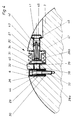
- Fig. 1:
- Gesamtansicht der Schneid- oder Perforiereinrichtung, teilweise im Schnitt dargestellt.
- Fig. 2:
- Schnitt des Messerzylinders entlang Linie II - II in
Figur 3. - Fig. 3:
- Teilansicht in Richtung III in
Figur 2. - Fig. 4:
- Detail von
Figur 2 in verändertem Maßstab und in Schnittebene gerückter Schraube.
- Fig. 1:
- General view of the cutting or perforating device, partially shown in section.
- Fig. 2:
- Section of the knife cylinder along line II - II in Figure 3.
- Fig. 3:
- Partial view in direction III in Figure 2.
- Fig. 4:
- Detail of Figure 2 in a modified scale and screw moved in the cutting plane.
Eine Bahn 1 aus Papier, Kunststoff, Metall, Folie, Gewebe od. dgl. läuft an einem Druckzylinder 2 vorbei und umschlingt diesen teilweise. Gleichzeitig durchläuft die Bahn 1 einen Walzenspalt, welcher durch den Druckzylinder 2 und den Messerzylinder 3 gebildet wird. Der Druckzylinder 2 und der Messerzylinder 3 sind mit Hilfe entsprechender Lager 4 in einem Maschinenrahmen 5 drehbar gelagert. Mindestens einer der beiden Zylinder 2 oder 3 ist angetrieben, es ist aber auch möglich, daß beide Zylinder durch Zahnräder, Zahnriemen od. dgl: miteinander verbunden sind, so daß sie in fester Phase zueinanderstehend umlaufen können. In diesem Fall ist es lediglich erforderlich, einen der beiden Zylinder anzutreiben, da der andere durch die aus Zahnrädern, Zahnriemen od. dgl. bestehende Synchronisiereinrichtung ebenfalls angetrieben wird. An dem Messerzylinder 3 sind Messer oder Messerpositionen 6, 7, 8, 9, 10 und 11 vorgesehen. Die an den Positionen 6 bis 11 befindlichen Messer erstrecken sich im wesentlichen in Richtung der geometrischen Achse des Messerzylinders 3 und sind zu dieser Achse Parallel oder schwach geneigt in dem Messerzylinder 3 befestigt. Die zugehörigen Messer können eine durchgehende Schneide oder aber auch eine durch querverlaufende Nuten unterbrochene Schneide aufweisen. In demjenigen Falle, in welchem die Messer eine durchgehende Schneide haben, wird die Bahn 1 beim Durchlauf durch den durch die Zylinder 2 und 3 gebildeten Walzenspalt in einzelne Bogen quer geschnitten. Wenn die Messer hingegen durch zu ihrer Schneide quer verlaufende Nuten in mehrere Einzelschneiden unterteilt sind, dann wird die Bahn 1 nicht vollkommen quer zu ihrer Laufrichtung durchgeschnitten. Es ergibt sich vielmehr eine Vielzahl von Einschnitten in die Bahn 1, wobei zwischen zwei Einschnitten ein brückenartiger Steg verbleibt. Auf diese Weise wird die Bahn 1 quer zu ihrer durch den Pfeil 12 angegebenen Laufrichtung perforiert. Aufgrund dieser Perforation ist es möglich, von der Bahn 1 in einem späteren Arbeitsgang einzelne Bogen abzureißen. Es ist beispielsweise jedoch ebenfalls möglich, daß diejenigen Stellen, an welchen die Bahn 1 durch quer verlaufende Perforationen geschwächt wird, Gelenkstellen bilden, in welchen die Bahn 1 bei einem späteren Zick-zack-Falzvorgang quer zu ihrer Laufrichtung geknickt werden kann.A web 1 made of paper, plastic, metal, foil, fabric or the like runs past a
Fig. 1 stellt ein Beispiel für einen Messerzylinder 3 dar, an dessen Umfang sechs Messer gleichmäßig verteilt angeordnet sind. Es ist hingegen ebenfalls möglich, den Messerzylinder 3 derart zu gestalten, daß an seinem Umfang auch eins, zwei, drei, vier, fünf, sieben, acht oder zehn Messer oder aber eine andere Anzahl von Messern gleichmäßig oder aber auch ungleichmäßig voneinander verteilt befestigt werden können. Entsprechend der Anzahl und Positionen der vorgesehenen Messer ist auch die Anzahl der für jedes Messer in den Messerzylinder eingearbeiteten zum Befestigen der Messer dienenden Nuten. Daneben ist es aber ebenfalls möglich, eine gewisse Anzahl von Nuten in den Messerzylinder 3 einzuarbeiten, bei dem jeweiligen Produktionsvorgang hingegen nur einen Teil dieser Nuten oder der Messer je nach dem vorliegenden Erfordernis der zu erzielenden Produktion zu benutzen und an den nichtbenutzten Positionen unwirksame, ggfs. sog. Blindmesser einzusetzen. Der Messerzylinder 3 und der Druckzylinder 2 sind in dem Maschinenrahmen 5 derart befestigt und drehbar gelagert, daß diese Maschinenteile insgesamt eine Baueinheit bilden, welche aus dem Hauptrahmen 13 der Maschine als Ganzes entnommen und gegen eine andere ähnliche Baueinheit ausgetauscht werden kann. Hierfür ist es erforderlich, den Maschinenrahmen 5 durch Spannpratzen 14 und 15, Mutter 16 und 17 sowie in den Hauptrahmen 13 eingeschraubte Zuganker 18 und 19 für die Zeit des Maschinenlaufes in dem Hauptrahmen 13 zu befestigen. Es ist hingegen aber ebenfalls möglich, den Maschinenrahmen 5 und die zugehörigen Befestigungseinrichtungen entfallen zu lassen und den Messerzylinder 3 sowie den Druckzylinder 2 in dem Hauptrahmen 13 der Maschine direkt zu lagern.Fig. 1 shows an example of a
Aus Fig. 2 wird ersichtlich, daß in den Messerzylinder 3 beispielsweise sechs Messerpositionen darstellende Nuten 20, 21, 22, 23, 24 und 25 eingearbeitet sind. Dabei ist die erste dieser Nuten 20 ausführlicher dargestellt, wohingegen die übrigen gleichartigen Nuten 21 - 25 durch strichpunktierte Geraden lediglich angedeutet sind. Jede der Nuten enthält eine Seitenwand 26, welche innerhalb des Zylinders 3 eine im wesentlichen radial zu diesem verlaufende Fläche darstellt. Parallel zu jeder Seitenwand 26 verlaufend enthält jede Nut eine zweite Seitenwand 27, welche ebenfalls in den Messerzylinder 3 eingearbeit ist.From Fig. 2 it can be seen that in the
Senkrecht zu der ersten Seitenwand 26 und der zweiten Seitenwand 27 verläuft die Grundfläche 28 jeder Nut mit ihren Teilen 28a und 28b. Jede Nut enthält somit die drei Flächen 26, 27 und 28. Nach radial außen des Messerzylinders 3 hin ist jede Nut offen. In jede Nut ist eine Beilage 29 derart eingesetzt, daß die Grundfläche 30 der Beilage 29 gegen den Teil 28a der Grundfläche der Nut anliegt. Jede Beilage 29 enthält mindestens eine Bohrung 31, durch die eine Schraube 32 hindurchgesteckt ist. Die Bohrung 31 der Beilage 29 hat vorzugsweise einen größeren Durchmesser als der Außendurchmesser der Schraube 32 beträgt. Die Schraube 32 ist in ein Gewinde 33 eingeschraubt, das in den Messerzylinder 3 derart eingearbeitet ist, daß die geometrische Achse der Schraube 32 zu den geometrischen Achsen der Druckmittelmittelzylinder 34, 35, 36 und 37, d. h. auch zur Grundfläche 28 der Nut 20 senkrecht steht. Die Druckmittelzylinder sind vorzugsweise aus Metall bestehende Balgenzylinder. Das in der Messerposition 6 befindliche Messer 6 (Nut 20) wird beispielsweise mit Hilfe des Druckmittelzylinders 34 unter Zwischenschaltung der Beilage 29 und eines kräftigen biegesteifen Stößels 38 gegen die Seitenwand 26 der Nut 20 gedrückt. Dabei wird der Stößel 38 in einer Durchbrechung 39 geführt, welche in einen in der Nut 20 befestigten leistenartigen Steg 40 eingearbeitet ist. Dieser leistenartige Steg kann beispielsweise am Grund der Nut 20 mit dem Messerzylinder 3 verschraubt sein und somit gegen die Grundfläche 28 der Nut 20 anliegen. Vorzugsweise besteht der Steg 40 jedoch aus dem gleichen Bauteil wie der Messerzylinder 3, d. h. er ist aus dem Material des Messerzylinders 3 herausgearbeitet. Dadurch, daß dem Druckmittelzylinder 34 Druckmittel aus den Kanälen 41, 42 und 43 zugeleitet wird, entsteht eine Kraft, die den Stößel 38 in Figur 4 nach links verschiebt, dadurch die Beilage 29 gegenüber der Schraube 32 soweit verschiebt wie es die Differenz von Durchmesser der Bohrung 31 und Außendurchmesser der Schraube 32 zuläßt und das Messer 6 von in Abbildung 4 rechts her gegen den Messerzylinder 3 drückt und mit diesem kraftschlüssig verspannt. Eine Bewegung der Beilage 29 gegenüber der Schraube 32 wird zudem noch dadurch begünstigt, daß zwischen dem Kopf der Schraube 32 und der Beilage 29 eine Druckfeder 44 eingesetzt ist.The
Die Kanäle 42 und 43 sind in eine Schraube 45 eingearbeitet, die ihrerseits mit einer Dichtung 46 versehen ist. Ebenso ist der Druckmittelzylinder 34 mit einer Dichtung 47 versehen. Der Steg 40 begrenzt bei entsprechender Wahl aller Abmessungen den Hub des Zylinders 34, was jedoch auf das Spannen des Messers 6 keine nachteiligen Wirkungen hat, da zwischen den Zylinder 34 und dem Messer 6 der Stößel 38 zwischengeschaltet ist, der etwas länger ist als die in Figur 4 sichtbare Breite des Steges 40, so daß für den Druckmittelzylinder genügend Bewegungsfreiheit bleibt, um das Messer 6 zu spannen oder zu lösen. Was hinsichtlich des Druckmittelzylinders 34 gilt, gilt in analoger Weise auch gegenüber allen anderen in den Messerzylinder 3 eingesetzten Druckmittelzylindern, beispielsweise gegenüber den weiteren Druckmittelzylindern 35, 36 und 37, die über die Länge des Messers 6 sowie der Länge aller weiteren Messer verteilt angeordnet sind. Die Druckmittelzylinder 34 und 35 halten beispielsweise den Abstand 48 untereinander ein, die Druckmittelzylinder 35 und 36 den Abstand 49 und die Druckmittelzylinder 36 und 37 den Abstand 50. Die entsprechenden, zugehörigen Durchbrechungen, wie beispielsweise durch die Durchbrechung 39 angedeutet, halten untereinander Abstände 51, 52 und 53 ein, derart, daß jede Durchbrechung konzentrisch zu dem jeweiligen Druckmittelzylinder angeordnet ist. In der gleichen Wirkungslinie liegt jeweils der jeweilige Stößel, wie beispielsweise der Stößel 38. Somit wird jeder Stößel durch den leistenartigen Steg 40 geführt, da sich jeder Stößel in einer entsprechenden Ausnehmung dieses Steges befindet und von dem Steg mit für seine Verschiebung genügend großem Spiel umschlossen wird. Steg 40 teilt Somit die Nut 20 in zwei Teilnuten mit den Grundflächen 28a und 28b, wobei der Steg 40 vorzugsweise die gesamte achsiale Länge des Zylinders 3 durchsetzt. Seine in Figur 4 als senkrecht laufende Kanten dargestellten Flächen laufen parallel zu den Seitenwänden 26 und 27 der Nut 20. Analoges gilt hinsichtlich aller übrigen für die Aufnahme von Messern vorgesehenen Nuten des Messerzylinders 3. Der Kanal 41 ist parallel zu der jeweiligen Nut in den Messerzylinder 3 eingearbeit. Er schneidet diejenigen Bohrungen, durch die die Schraube 45 oder weitere analoge Schrauben hindurchgesteckt sind, so daß sich ein zusammenhängendes Kanalsystem zumindest je Nut oder aber mit Hilfe entsprechender Rohrleitungen auch für alle Nuten ergibt. Das jeweilige Kanalsystem steht seinerseits mit einem Druckerzeuger in Verbindung.
Claims (6)
- Cutter cylinder (3) for processing web-like material (1) made of paper, synthetic or metal foils, fabrics or the like, having at least one groove (20 - 25) which is provided for receiving and securing in each case one cutter (6 - 11) arranged substantially parallel to the axis of rotation of the cutter cylinder (3), which is also arranged parallel to the axis of rotation of the cutter cylinder (3) on the periphery thereof and which is made in the cutter cylinder (3), and pressure points which are arranged distributed over the length of each cutter (6 - 11) for clamping the respective cutter (6) with respect to the cutter cylinder (3) by means of a plurality of pressurized medium cylinders (34 - 37) which are arranged distributed over the length of each cutter (6 - 11) and which press the respective cutter (6 - 11) against the cutter cylinder (3), and having a channel system (41 - 43) which rotates with the cutter cylinder (3) and is connected to the pressurized medium cylinders (34 - 37), and for each cutter (6 - 11) at least one shim (29) arranged between this cutter (6) and a pressurized medium cylinder (34) associated therewith, the pressurized medium cylinders (34 - 37) associated with each groove (20 - 25) being arranged both within the groove (20 - 25) and substantially in the peripheral direction of the cutter cylinder (3), and the pressurized medium cylinders (34 - 37) preferably being bellows cylinders made of metal, characterized by a device (40) for limiting the stroke of each of the pressurized medium cylinders (34 - 37), in the form of a strip-type rib (40) which is secured within the respective groove (20 - 25) and has at least one aperture (39), a tappet (38) being inserted in each aperture (39) between each pressurized medium cylinder (34 - 37) and the shim (29) of the respective cutter (6) and being guided by the strip-type rib (40).
- Device according to Claim 1, characterized in that the strip-type rib (40) and the cutter cylinder (3) comprise the same structural component.
- Device according to Claim 1, characterized in that the mutual spacings (51 - 53) between the apertures (39) correspond to the mutual spacings (48 - 50) between the respective pressurized medium cylinders (34 - 37).
- Device according to Claim 1, characterized in that each shim (29) contains at least one bore (31) directed perpendicular to the base surface (28) of each groove (20 - 25).
- Device according to Claims 1 and 4, characterized in that the bore (31) has an internal diameter which is larger than the external diameter of a screw (32) pushed through it.
- Device according to Claim 1, characterized in that the pressurized medium is supplied to each pressurized medium cylinder (34 - 37) through a respective channel (41) made in the cutter cylinder (3) parallel to the respective groove (20 - 25).
Applications Claiming Priority (3)
| Application Number | Priority Date | Filing Date | Title |
|---|---|---|---|
| DE3934525A DE3934525A1 (en) | 1989-10-17 | 1989-10-17 | KNIFE CYLINDER |
| DE3934525 | 1989-10-17 | ||
| PCT/DE1990/000760 WO1991005641A1 (en) | 1989-10-17 | 1990-10-08 | Cutting cylinder |
Publications (2)
| Publication Number | Publication Date |
|---|---|
| EP0496741A1 EP0496741A1 (en) | 1992-08-05 |
| EP0496741B1 true EP0496741B1 (en) | 1994-04-27 |
Family
ID=6391581
Family Applications (1)
| Application Number | Title | Priority Date | Filing Date |
|---|---|---|---|
| EP90914133A Expired - Lifetime EP0496741B1 (en) | 1989-10-17 | 1990-10-08 | Cutting cylinder |
Country Status (7)
| Country | Link |
|---|---|
| US (1) | US5159868A (en) |
| EP (1) | EP0496741B1 (en) |
| JP (1) | JP2550221B2 (en) |
| CA (1) | CA2069307C (en) |
| DE (2) | DE3934525A1 (en) |
| ES (1) | ES2029987T3 (en) |
| WO (1) | WO1991005641A1 (en) |
Families Citing this family (16)
| Publication number | Priority date | Publication date | Assignee | Title |
|---|---|---|---|---|
| DE4139137A1 (en) * | 1991-11-28 | 1993-06-03 | Will E C H Gmbh & Co | METHOD AND DEVICE FOR ADJUSTING THE KNIVES OF A FORMAT CUTTER |
| DE19526507C2 (en) * | 1995-07-20 | 1999-04-08 | Wifag Maschf | Knife cylinder with adjustable knife bar |
| US5890410A (en) * | 1997-03-19 | 1999-04-06 | Hinojosa; Domingo | Holding assembly for cutting blade |
| US6244151B1 (en) * | 1998-06-11 | 2001-06-12 | Tamarack Products Inc. | Apparatus for adjusting cutting bar |
| JP2000317885A (en) * | 1999-05-06 | 2000-11-21 | Sanwa Kako Co Ltd | Method and device for machining synthetic resin foam into rectangular shape |
| US7454753B2 (en) * | 2001-06-27 | 2008-11-18 | International Business Machines Corporation | Semaphore management subsystem for use with multi-thread processor systems |
| US7007580B2 (en) * | 2002-04-11 | 2006-03-07 | Goss International Americas, Inc. | Apparatus for removably securing a cutting component |
| ATE461795T1 (en) * | 2004-10-08 | 2010-04-15 | Western Printing Mach Co | DIE HOLDING DEVICE FOR ROTARY CUTTING SYSTEM |
| DE102007058816A1 (en) * | 2007-12-05 | 2009-06-10 | Krones Ag | Cutting tool for cutting labels |
| DE102007058819A1 (en) * | 2007-12-05 | 2009-06-10 | Krones Ag | Strip cutter especially label strips with roller rotating around rotation axis has force recording sensor coupled to cutting bar or element useful in label production technology lessens blade blunting and ensures longer tool life |
| US9278417B2 (en) | 2013-01-09 | 2016-03-08 | Illinois Tool Works Inc. | Pipe machining apparatuses and methods of operating the same |
| US10328493B2 (en) | 2013-01-09 | 2019-06-25 | Illinois Tool Works Inc. | Pipe machining apparatuses and methods of operating the same |
| US9399306B2 (en) * | 2013-01-09 | 2016-07-26 | Illinois Tool Works Inc. | Pipe machining apparatuses and methods of operating the same |
| US9610636B2 (en) | 2013-01-09 | 2017-04-04 | Illinois Tool Works Inc. | Pipe machining apparatuses and methods of operating the same |
| US10203030B2 (en) | 2015-07-02 | 2019-02-12 | Illinois Tool Works Inc. | Gearing arrangement |
| MX2018001813A (en) | 2015-08-12 | 2018-05-16 | Illinois Tool Works | Crash resistant trip for a pipe for a machining apparatus. |
Family Cites Families (6)
| Publication number | Priority date | Publication date | Assignee | Title |
|---|---|---|---|---|
| US3769868A (en) * | 1971-04-19 | 1973-11-06 | Strucker O Kg | Transverse cutting machine |
| US4131047A (en) * | 1977-03-28 | 1978-12-26 | Harris Corporation | Rotary knife mounting |
| DE3303628A1 (en) * | 1983-02-03 | 1984-08-09 | Maschinenfabrik Goebel Gmbh, 6100 Darmstadt | KNIFE CYLINDERS FOR PROCESSING RAILWAY GOODS |
| DE3507929A1 (en) * | 1985-03-06 | 1986-09-11 | Maschinenfabrik Goebel Gmbh, 6100 Darmstadt | KNIFE CYLINDERS FOR PROCESSING RAILWAY GOODS |
| US4715250A (en) * | 1986-06-27 | 1987-12-29 | Rosemann Thomas J | Rotary cutting cylinder and method of making same |
| DE8712804U1 (en) * | 1987-09-23 | 1987-12-03 | Kilper, Karl, 7255 Rutesheim, De |
-
1989
- 1989-10-17 DE DE3934525A patent/DE3934525A1/en not_active Withdrawn
-
1990
- 1990-10-08 US US07/689,823 patent/US5159868A/en not_active Expired - Fee Related
- 1990-10-08 JP JP2513234A patent/JP2550221B2/en not_active Expired - Lifetime
- 1990-10-08 ES ES90914133T patent/ES2029987T3/en not_active Expired - Lifetime
- 1990-10-08 EP EP90914133A patent/EP0496741B1/en not_active Expired - Lifetime
- 1990-10-08 DE DE59005554T patent/DE59005554D1/en not_active Expired - Lifetime
- 1990-10-08 CA CA002069307A patent/CA2069307C/en not_active Expired - Fee Related
- 1990-10-08 WO PCT/DE1990/000760 patent/WO1991005641A1/en active IP Right Grant
Also Published As
| Publication number | Publication date |
|---|---|
| EP0496741A1 (en) | 1992-08-05 |
| JP2550221B2 (en) | 1996-11-06 |
| US5159868A (en) | 1992-11-03 |
| CA2069307C (en) | 1995-01-24 |
| WO1991005641A1 (en) | 1991-05-02 |
| ES2029987T1 (en) | 1992-10-16 |
| DE3934525A1 (en) | 1991-04-18 |
| ES2029987T3 (en) | 1994-07-16 |
| JPH03505555A (en) | 1991-12-05 |
| DE59005554D1 (en) | 1994-06-01 |
Similar Documents
| Publication | Publication Date | Title |
|---|---|---|
| EP0496741B1 (en) | Cutting cylinder | |
| DE69909978T2 (en) | PERFORATING DEVICE WITH KNIFE SHAFT WITH UNIFORM DISTRIBUTED PERFORATING KNIVES | |
| DE60018953T2 (en) | VACUUM SUPPORTED ROLLING DEVICE AND METHOD | |
| EP0115783B1 (en) | Rotary cutter cylinder for cutting webs | |
| EP0802277A2 (en) | Machine for making a web material | |
| EP2353810A1 (en) | Device for treating a sheet of material | |
| EP0196688B1 (en) | Knife cylinder for machining webs of material | |
| DE2513461A1 (en) | LOCKING DEVICE FOR CUTTING HEADS OF PAPER PROCESSING MACHINES | |
| DE19949223A1 (en) | Device for cutting material web in rotary printing machine involves blade cylinder with at least one blade arrangement on its periphery and support body opposite to blade cylinder | |
| DE2301586A1 (en) | ARRANGEMENT FOR THE PRODUCTION OF MULTI-LAYER TEAR BLOCKS | |
| DE10356037A1 (en) | Corrugated cardboard web cutting device that can be used to make incomplete transverse cuts has knife and counter rollers that are controlled by a control unit so that a counter body and knife are displaced relative to each other | |
| EP0802026B1 (en) | Perforating appparatus for foils, especially plastic foils | |
| EP0707930B1 (en) | Cutting stick for a perforating device | |
| EP0127806A2 (en) | Apparatus for perforating webs | |
| DE1291188B (en) | Cutting knife for a perforation machine | |
| DE3738196C2 (en) | ||
| WO1999030909B1 (en) | Printed product | |
| EP0255626B1 (en) | Pair of shaft-blades for cutting web material, particulary corrugated board | |
| DE102017129367B4 (en) | Carrier element for receiving punching lines, punching die comprising the carrier element and method for producing the punching die | |
| EP1567342B1 (en) | Ink reservoir doctor blade | |
| EP0695710A2 (en) | Adhesive means arrangement for a replacement paper web roll | |
| DE69927393T2 (en) | PUNCH UNIT | |
| DE3526248A1 (en) | Device for punching webs in a rotary manner | |
| DE4034796A1 (en) | Mounting device for cylinder pairs for processing paper film, etc. - in which each outer bearing is located in auxiliary housing and subjected to forces facing away from contact line of cylinders | |
| DE2300635C2 (en) | Device for punching and creasing and / or embossing paper, cardboard or similar materials |
Legal Events
| Date | Code | Title | Description |
|---|---|---|---|
| PUAI | Public reference made under article 153(3) epc to a published international application that has entered the european phase |
Free format text: ORIGINAL CODE: 0009012 |
|
| 17P | Request for examination filed |
Effective date: 19910617 |
|
| AK | Designated contracting states |
Kind code of ref document: A1 Designated state(s): CH DE ES FR GB IT LI NL |
|
| ITCL | It: translation for ep claims filed |
Representative=s name: BARZANO' E ZANARDO MILANO S.P.A. |
|
| TCNL | Nl: translation of patent claims filed | ||
| 17Q | First examination report despatched |
Effective date: 19931011 |
|
| GRAA | (expected) grant |
Free format text: ORIGINAL CODE: 0009210 |
|
| ITF | It: translation for a ep patent filed |
Owner name: BARZANO' E ZANARDO MILANO S.P.A. |
|
| AK | Designated contracting states |
Kind code of ref document: B1 Designated state(s): CH DE ES FR GB IT LI NL |
|
| REF | Corresponds to: |
Ref document number: 59005554 Country of ref document: DE Date of ref document: 19940601 |
|
| GBT | Gb: translation of ep patent filed (gb section 77(6)(a)/1977) |
Effective date: 19940511 |
|
| ET | Fr: translation filed | ||
| REG | Reference to a national code |
Ref country code: ES Ref legal event code: FG2A Ref document number: 2029987 Country of ref document: ES Kind code of ref document: T3 |
|
| PLBE | No opposition filed within time limit |
Free format text: ORIGINAL CODE: 0009261 |
|
| STAA | Information on the status of an ep patent application or granted ep patent |
Free format text: STATUS: NO OPPOSITION FILED WITHIN TIME LIMIT |
|
| 26N | No opposition filed | ||
| PGFP | Annual fee paid to national office [announced via postgrant information from national office to epo] |
Ref country code: FR Payment date: 19960930 Year of fee payment: 7 Ref country code: DE Payment date: 19960930 Year of fee payment: 7 |
|
| PGFP | Annual fee paid to national office [announced via postgrant information from national office to epo] |
Ref country code: ES Payment date: 19961007 Year of fee payment: 7 |
|
| PGFP | Annual fee paid to national office [announced via postgrant information from national office to epo] |
Ref country code: NL Payment date: 19961031 Year of fee payment: 7 |
|
| PGFP | Annual fee paid to national office [announced via postgrant information from national office to epo] |
Ref country code: GB Payment date: 19961112 Year of fee payment: 7 |
|
| PGFP | Annual fee paid to national office [announced via postgrant information from national office to epo] |
Ref country code: CH Payment date: 19961114 Year of fee payment: 7 |
|
| PG25 | Lapsed in a contracting state [announced via postgrant information from national office to epo] |
Ref country code: DE Effective date: 19970910 |
|
| PG25 | Lapsed in a contracting state [announced via postgrant information from national office to epo] |
Ref country code: GB Free format text: LAPSE BECAUSE OF NON-PAYMENT OF DUE FEES Effective date: 19971008 |
|
| PG25 | Lapsed in a contracting state [announced via postgrant information from national office to epo] |
Ref country code: ES Free format text: LAPSE BECAUSE OF EXPIRATION OF PROTECTION Effective date: 19971009 |
|
| PG25 | Lapsed in a contracting state [announced via postgrant information from national office to epo] |
Ref country code: LI Free format text: LAPSE BECAUSE OF NON-PAYMENT OF DUE FEES Effective date: 19971031 Ref country code: FR Free format text: THE PATENT HAS BEEN ANNULLED BY A DECISION OF A NATIONAL AUTHORITY Effective date: 19971031 Ref country code: CH Free format text: LAPSE BECAUSE OF NON-PAYMENT OF DUE FEES Effective date: 19971031 |
|
| PG25 | Lapsed in a contracting state [announced via postgrant information from national office to epo] |
Ref country code: NL Free format text: LAPSE BECAUSE OF NON-PAYMENT OF DUE FEES Effective date: 19980501 |
|
| GBPC | Gb: european patent ceased through non-payment of renewal fee |
Effective date: 19971008 |
|
| REG | Reference to a national code |
Ref country code: CH Ref legal event code: PL |
|
| NLV4 | Nl: lapsed or anulled due to non-payment of the annual fee |
Effective date: 19980501 |
|
| REG | Reference to a national code |
Ref country code: FR Ref legal event code: ST |
|
| REG | Reference to a national code |
Ref country code: ES Ref legal event code: FD2A Effective date: 20010201 |
|
| PG25 | Lapsed in a contracting state [announced via postgrant information from national office to epo] |
Ref country code: IT Free format text: LAPSE BECAUSE OF NON-PAYMENT OF DUE FEES;WARNING: LAPSES OF ITALIAN PATENTS WITH EFFECTIVE DATE BEFORE 2007 MAY HAVE OCCURRED AT ANY TIME BEFORE 2007. THE CORRECT EFFECTIVE DATE MAY BE DIFFERENT FROM THE ONE RECORDED. Effective date: 20051008 |