EP1990191A2 - Web-fed printing press - Google Patents
Web-fed printing press Download PDFInfo
- Publication number
- EP1990191A2 EP1990191A2 EP08008639A EP08008639A EP1990191A2 EP 1990191 A2 EP1990191 A2 EP 1990191A2 EP 08008639 A EP08008639 A EP 08008639A EP 08008639 A EP08008639 A EP 08008639A EP 1990191 A2 EP1990191 A2 EP 1990191A2
- Authority
- EP
- European Patent Office
- Prior art keywords
- cylinder
- web
- printing
- transfer cylinder
- rubber
- Prior art date
- Legal status (The legal status is an assumption and is not a legal conclusion. Google has not performed a legal analysis and makes no representation as to the accuracy of the status listed.)
- Withdrawn
Links
Images

Classifications
-
- B—PERFORMING OPERATIONS; TRANSPORTING
- B41—PRINTING; LINING MACHINES; TYPEWRITERS; STAMPS
- B41F—PRINTING MACHINES OR PRESSES
- B41F13/00—Common details of rotary presses or machines
- B41F13/08—Cylinders
- B41F13/193—Transfer cylinders; Offset cylinders
-
- B—PERFORMING OPERATIONS; TRANSPORTING
- B41—PRINTING; LINING MACHINES; TYPEWRITERS; STAMPS
- B41F—PRINTING MACHINES OR PRESSES
- B41F13/00—Common details of rotary presses or machines
- B41F13/08—Cylinders
- B41F13/10—Forme cylinders
-
- B—PERFORMING OPERATIONS; TRANSPORTING
- B41—PRINTING; LINING MACHINES; TYPEWRITERS; STAMPS
- B41F—PRINTING MACHINES OR PRESSES
- B41F30/00—Devices for attaching coverings or make-ready devices; Guiding devices for coverings
- B41F30/04—Devices for attaching coverings or make-ready devices; Guiding devices for coverings attaching to transfer cylinders
-
- B—PERFORMING OPERATIONS; TRANSPORTING
- B41—PRINTING; LINING MACHINES; TYPEWRITERS; STAMPS
- B41N—PRINTING PLATES OR FOILS; MATERIALS FOR SURFACES USED IN PRINTING MACHINES FOR PRINTING, INKING, DAMPING, OR THE LIKE; PREPARING SUCH SURFACES FOR USE AND CONSERVING THEM
- B41N6/00—Mounting boards; Sleeves Make-ready devices, e.g. underlays, overlays; Attaching by chemical means, e.g. vulcanising
-
- B—PERFORMING OPERATIONS; TRANSPORTING
- B41—PRINTING; LINING MACHINES; TYPEWRITERS; STAMPS
- B41P—INDEXING SCHEME RELATING TO PRINTING, LINING MACHINES, TYPEWRITERS, AND TO STAMPS
- B41P2227/00—Mounting or handling printing plates; Forming printing surfaces in situ
- B41P2227/10—Attaching several printing plates on one cylinder
- B41P2227/11—Attaching several printing plates on one cylinder in axial direction
-
- B—PERFORMING OPERATIONS; TRANSPORTING
- B41—PRINTING; LINING MACHINES; TYPEWRITERS; STAMPS
- B41P—INDEXING SCHEME RELATING TO PRINTING, LINING MACHINES, TYPEWRITERS, AND TO STAMPS
- B41P2227/00—Mounting or handling printing plates; Forming printing surfaces in situ
- B41P2227/20—Means enabling or facilitating exchange of tubular printing or impression members, e.g. printing sleeves, blankets
Definitions
- the invention relates to a web-fed printing machine, in particular an illustrations-printing machine, according to the preamble of claim 1 or 10.
- a printing unit of an offset web press in addition to a forme cylinder, an inking unit and optionally a dampening unit further comprises a transfer cylinder, with the aid of the transfer cylinder ink can be transferred to a printing material to be printed.
- the transmission cylinder is assigned a transmission system.
- the form cylinder is assigned a printing plate system.
- Blankets and blankets also known as metal back blankets, are stretched on the transfer cylinder in chutes. Rubber sleeves are pushed onto the transfer cylinder in the axial direction and do not require any chan- nel channels. For rapport-free printing in exciting channels to rubber blankets or blanket plates are not suitable, but this rubber sleeves must be used, namely those that are seamless on their surface.
- the present invention has the object to provide a novel web printing press.
- the first aspect of the invention as well as the second aspect of the invention may be used either alone or in combination with each other on a web-fed printing machine.
- the transmission system according to the first aspect of the invention comprises a plurality of rubber sleeves and the pressure molding system according to the second aspect of the present invention comprises a plurality of molding sleeves each positioned adjacent to each other in the axial direction of the respective cylinder.
- This allows the economical use of sleeving technology in transfer cylinders and form cylinders with a large axial width.
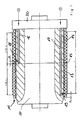
- Fig. 1 and 2 show a transfer cylinder 10 of a printing unit of a web-fed printing press according to the invention, in particular an illustration printing press, wherein the transfer cylinder 10 is assigned a transmission system 11 is soft on an outer surface 12 of the transfer cylinder 10 is arranged or pushed onto this outer surface 12.
- the transmission system 11 comprises two rubber sleeves 13, 14 arranged side by side in the axial direction of the transfer cylinder 10.
- Fig. 1 shows the transfer cylinder 10 in a state in which both rubber sleeves 13, 14 are pushed onto the outer surface 12 thereof.
- Fig. 2 shows, however, the transfer cylinder 10 exclusively together with the rubber sleeve 14th
- Fig. 1 Transmission system 11 shown is divided so that a joint 15 between the directly juxtaposed rubber sleeves 13, 14 in the middle of the printing-used width L of the transfer cylinder 10 and the transmission system 11 is located.
- Each rubber sleeve 13, 14 therefore has a printing width of% L.
- the joint 15 between the two rubber sleeves 13, 14, which are positioned next to each other on the transfer cylinder 10 in the axial direction, is located at a non-printing location or a non-printing axial position of the transfer cylinder 10, in particular at an axial position of a longitudinal fold to be formed on the printed substrate and / or longitudinal section.
- an independent compressed air system 16 or 17 is integrated into the transfer cylinder 10 for each rubber sleeve 13, 14 ,
- the compressed air system 16 has air openings 18 and the compressed air system 17 via air openings 19, which respectively open on the outer surface 12 of the transfer cylinder 10.
- An air pressure p can be provided to the compressed air system 16 in order to build up an air cushion when mounting or dismounting or removing the rubber sleeves 13, 14 between the surface 12 of the transfer cycle 10 and the respective rubber sleeve 13, 14.
- the opening on the surface of the transfer cylinder 10 air holes 18, 19 of the compressed air systems 16, 17 are spaced apart such that the axial distance between the air holes 18, 19 of the two compressed air systems 16, 17 is either smaller or equal to the axial extent of the Rubber sleeves 13, 14. This may work best Fig. 2 taken from the rubber sleeve 14 when mounting or dismounting the same on the transfer cylinder 10.
- Fig. 2 So shows Fig. 2 in that the rubber sleeve 14 covers both the air bores 18 of the compressed air system 16 and the air bores 19 of the compressed air system 17 in the position shown. This ensures that when mounting or mounting and dismounting or removing the air cushion between the rubber sleeve 14 and the outer surface 12 of the transfer cylinder 10 does not depart.
- the air holes 18, 19 have in the assembled state of the two rubber sleeves 13, 14 from a seen in the lift direction rear edge of the rubber sleeves 13, 14 a defined distance A and B on.
- the forme cylinder 10 has a portion 20 which protrudes relative to the outer surface 12 and thus forms a stop for the front rubber sleeve 14 seen in the lift direction.
- the transfer cylinder associated transmission system comprises a plurality of rubber sleeves.
- the transfer cylinder associated transmission system comprises a plurality of rubber sleeves.
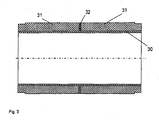
- a continuous carrier sleeve 30 eg made of nickel
- two or more rubber hoists 31 are closed by seals 32.
- seals 32 it is advantageous simply possible to produce rubber tires with narrow width a wider overall sleeve.
- the inventive concept is not limited to transfer cylinders and transmission systems, but the invention can also be used in Formzytindern and printing plate systems.
- the above explanations apply analogously to pressure-forming systems designed in several parts in the axial direction of a forme cylinder, in which case the pressure-forming systems preferably comprise a plurality of shaping sleeves positioned next to one another in the axial direction.
- the form cylinder is preferably associated with a continuous clamping channel without offset for receiving the multi-part printing form system.
- Each of the part-width printing plates preferably has a mechanical register system which is accommodated in the forme cylinder.
- the clamping channel accommodates a clamping or clamping system for the printing plates.
- the deviation of the outer diameter is up to 0.04 millimeters. This can lead to different conveying behavior and wrinkling on the paper web when several such rubber sleeves are used together on a transfer cylinder of an offset printing press, in particular at the joints of two rubber sleeves. Especially with large web tension, as is usually the case with commercial printing presses, such wrinkles can also lead to web breaks. Web breaks can damage the press and in any case lead to downtime.
- the outer rubber layer is usually ground to achieve a predetermined surface roughness and a given dimension for the diameter.
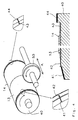
- the (two or more) rubber sleeves 13, 14 to be used together are received together on a so-called master cylinder 40 and ground together by a grinding device 50 to the predetermined diameter and finished therewith.
- Corresponding devices for finishing rubber sleeve or rubber sleeves are well known.
- the master cylinder 40 is preferably rotatably mounted on both sides, wherein at least one storage for the assembly or disassembly of sleeves can be removed.
- the master cylinder 40 is preferably provided with an air system that can create an air cushion under a sleeve.
- the grinding device 50 is vorzumik from a rotating grinding wheel 50, which is on the surface of the mother cylinder 40 on and off.
- the grinding device 50 moves under the action of the surface of the rubber sleeves 13, 14 in the axial direction (arrow A) over the entire length of the mounted rubber sleeves 13,14, possibly also in addition with an overflow.
- the grinding operation is preferably carried out in synchronism, ie, the rotation of the nut cylinder 40 and the direction of rotation of the grinding wheel 50 run at the contact point in the same direction. Of course, a reverse grinding would be possible.
- the two or more rubber sleeves have an identical outer diameter and an identical surface roughness so that a homogeneous web tension is ensured and wrinkling of the paper web is avoided.
- the rubber sleeves 13, 14, which have been finished together, must be marked accordingly are used and together on a transfer cylinder of a printing press.
- the already existing on the metallic inner sleeve marking preferably supplemented by a corresponding reference to a pairwise production or more sleeves. Since during finishing, despite the greatest care over the processing length slight differences in diameter (within the tolerance limits) may occur, it is particularly advantageous if the rubber sleeves are applied in exactly the mounting position on the transfer cylinder, which they had also taken during the finishing. That is, the rubber sleeves are preferably mounted with the same end sides as in the finishing machining against each other on a transfer or blanket cylinder. At the rubber sleeves 13, 14 corresponding labels are provided. For this example, small grooves 42, 43 are arranged in non-printing area of the sleeves.
- the rubber sleeves are preferably aligned with respect to their circumferential position so on the transfer cylinder / blanket cylinder to each other that it corresponds to the circumferential position on the master cylinder during finishing.
- markings are preferably applied to the rubber sleeves 13, 14 and the master cylinder 40 as well as the blanket cylinders of the printing press. Such markings may for example be designed as dashes 41, 44 on the master cylinder and rubber or transfer cylinder or as small grooves, comparable to those on the rubber sleeves.
Abstract
Description
Die Erfindung betrifft eine Rollendruckmaschine, insbesondere eine illustrations-druckmaschine, gemäß dem Oberbegriff des Anspruchs 1 bzw. 10.The invention relates to a web-fed printing machine, in particular an illustrations-printing machine, according to the preamble of
Ein Druckwerk einer Offset-Rollendruckmaschine weist neben einem Formzylinder, einem Farbwerk sowie gegebenenfalls einem Feuchtwerk weiterhin einen Übertragungszylinder auf, wobei mit Hilfe des Übertragungszylinders Druckfarbe auf einen zu bedruckenden Bedruckstoff übertragen werden kann. Dem Übertragungszylinder ist ein Übertragungssystem zugeordnet. Dem Formzylinder ist ein Druckformsystem zugeordnet.A printing unit of an offset web press, in addition to a forme cylinder, an inking unit and optionally a dampening unit further comprises a transfer cylinder, with the aid of the transfer cylinder ink can be transferred to a printing material to be printed. The transmission cylinder is assigned a transmission system. The form cylinder is assigned a printing plate system.
Bei Übertragungssystemen unterscheidet man zwischen Gummituchsystemen, Gummituchpiattensystemen und Gummisleevesystemen. Gummitücher und Gummituchplatten, die auch als Metal Back Blanket bezeichnet werden, werden auf dem Übertragungszylinder in Spannkanälen gespannt. Gummisleeves werden in Axialrichtung auf den Übertragungszylinder aufgeschoben und benötigen keine Spannkanäle. Zum rapportfreien Drucken sind in Spannkanälen zu spannende Gummitücher bzw. Gummituchplatten nicht geeignet, vielmehr müssen hierzu Gummisleeves verwendet werden, und zwar solche, die an ihrer Oberfläche nahtlos ausgebildet sind.In transmission systems, a distinction is made between blanket systems, rubber blanket systems and rubber sleeve systems. Blankets and blankets, also known as metal back blankets, are stretched on the transfer cylinder in chutes. Rubber sleeves are pushed onto the transfer cylinder in the axial direction and do not require any chan- nel channels. For rapport-free printing in exciting channels to rubber blankets or blanket plates are not suitable, but this rubber sleeves must be used, namely those that are seamless on their surface.
Bei Druckformsystemen unterscheidet man zwischen Druckplattensystemen und Formsleevesystemen. Druckplatten werden auf dem Formzylinder in Spannkanälen gespannt. Formsleeves werden hingegen in Axialrichtung auf den Formzylinder aufgeschoben und benötigen keine Spannkanäle.In the case of printing form systems, a distinction is made between printing plate systems and form-sleeve systems. Printing plates are clamped on the form cylinder in clamping channels. Formsleeves, however, are pushed in the axial direction of the form cylinder and do not require clamping channels.
Insbesondere in Offset-Illustrationsdruckmaschinen finden bislang Übertragungssysteme sowie Druckformsysteme Verwendung, die an die axiale Breite des Übertragungszylinders bzw. Formzylinders angepasst sind und sich ununterbrochen über die gesamte drucktechnisch genutzte axiale Breite des Übertragungszylinders bzw. Formzylinders erstrecken. Mit zunehmender axialer Breite des Übertragungszylinders bzw. des Formzylinders steigen die Herstellungskosten solcher Übertragungssysteme sowie Druckformsysteme.In particular, in offset-illustration printing presses hitherto transfer systems and printing-plate systems have been used which are adapted to the axial width of the transfer cylinder or forme cylinder and extend uninterruptedly over the entire utilized axial width of the transfer cylinder or forme cylinder. With increasing axial width of the transfer cylinder or of the forme cylinder, the production costs of such transfer systems and printing form systems increase.
Weiterhin kann mit zunehmend größeren axialen Breiten der Übertragungssysteme sowie Druckformsysteme eine konstante Druckqualität über die gesamte drucktechnisch genutzte axiale Breite so gut wie nicht mehr gewährleistet werden. Desweiteren bereitet aufgrund der zunehmenden Dimensionen sowie des zunehmenden Gewichts solcher Übertragungssysteme sowie Druckformsysteme die Handhabung derselben Schwierigkeiten.Furthermore, with increasingly larger axial widths of the transmission systems and printing plate systems, a constant print quality over the entire width of the printing technology used as good as can no longer be guaranteed. Furthermore, due to the increasing dimensions as well as the increasing weight of such transmission systems as well as printing form systems, the handling of the same difficulties is occurring.
Hiervon ausgehend liegt der vorliegenden Erfindung die Aufgabe zugrunde, eine neuartige Rollendruckmaschine zu schaffen.On this basis, the present invention has the object to provide a novel web printing press.
Diese Aufgabe wird nach einem ersten Aspekt der Erfindung durch eine Rollendruckmaschine gemäß Anspruch 1 gelöst. Hiernach ist das dem Übertragungszylinder des oder jedes Druckwerks zugeordnete Übertragungssystem in Axialrichtung des Übertragungszylinders mehrteilig ausgebildet.This object is achieved according to a first aspect of the invention by a web-fed printing machine according to claim 1. After that, the transmission cylinder of the or each printing unit associated transmission system is formed in several parts in the axial direction of the transfer cylinder.
Diese Aufgabe wird nach einem zweiten Aspekt der Erfindung durch eine Rollendruckmaschine gemäß Anspruch 11 gelöst. Hiernach ist dem Formzylinder des oder jedes Druckwerks zugeordnete Druckformsystem in Axialrichtung des Formzylinders mehrteilig ausgebildet.This object is achieved according to a second aspect of the invention by a web-fed printing press according to claim 11. Thereafter, the form cylinder of the or each printing unit associated printing form system is formed in several parts in the axial direction of the forme cylinder.
Der erste Aspekt der Erfindung sowie der zweite Aspekt der Erfindung können entweder alleine oder in Kombination miteinander an einer Rollendruckmaschine verwendet werden.The first aspect of the invention as well as the second aspect of the invention may be used either alone or in combination with each other on a web-fed printing machine.
Bevorzugt umfasst das Übertragungssystem nach dem ersten Aspekt der Erfindung mehrere Gummisleeves und das Druckformsystem nach dem zweiten Aspekt der hier vorliegenden Erfindung mehrere Formsleeves, die jeweils in Axialrichtung des jeweiligen Zylinders nebeneinander auf demselben positioniert sind. Dies erlaubt die wirtschaftliche Nutzung der Sleevetechnologie bei Übertragungszylindern und Formzylindern mit einer großen axialen Breite.Preferably, the transmission system according to the first aspect of the invention comprises a plurality of rubber sleeves and the pressure molding system according to the second aspect of the present invention comprises a plurality of molding sleeves each positioned adjacent to each other in the axial direction of the respective cylinder. This allows the economical use of sleeving technology in transfer cylinders and form cylinders with a large axial width.
Bevorzugte Weiterbildungen der Erfindung ergeben sich aus den Unteransprüchen und der nachfolgenden Beschreibung. Ausführungsbeispiele der Erfindung werden, ohne hierauf beschränkt zu sein, an Hand der Zeichnung näher erläutert. Dabei zeigt:
- Fig. 1:
- einen Querschnitt durch, einen Übertragungszylinder einer erfindungsgemäßen Rollendruckmaschine zusammen mit einem auf dem Übertragungszylinder positionierten Übertragungssystem;
- Fig. 2:
- den Übertragungszylinder der
Fig. 1 beim Aufschieben eines ersten Teils des Übertragungssystems - Fig. 3:
- ein Übertragungssystem, bestehend aus einem durchgehenden Trägersleeve mit zwei Gummiaufzügen
- Fig. 4:
- eine schematisch dargestellte Vorrichtung zum Fertigbearbeiten von Gummisleeves.
- Fig. 1:
- a cross section through, a transfer cylinder of a web-fed printing press according to the invention together with a transmission system positioned on the transfer cylinder;
- Fig. 2:
- the transfer cylinder of
Fig. 1 when postponing a first part of the transmission system - 3:
- a transmission system, consisting of a continuous carrier sleeve with two rubber lifts
- 4:
- a schematically illustrated device for finishing rubber sleeves.
Im gezeigten Ausführungsbeispiel der
Das in
Die Stoßstelle 15 zwischen den beiden Gummisleeves 13, 14, die in Axialrichtung nebeneinander auf dem Übertragungszylinder 10 positioniert sind, liegt an einer nicht-druckenden Stelle bzw. einer nicht-druckenden Axialposition des Übertragungszylinders 10, insbesondere an einer Axialposition eines am bedruckten Bedruckstoff auszubildenden Längsfalzes und/oder Längsschnitts.The
Obwohl in
Um ein Montieren bzw. Aufziehen und ein Demontieren bzw. Abziehen der Gummisleeves 13, 14 des Übertragungssystems 11 auf den bzw. von dem Übertragungszylinder 10 zu ermöglichen, ist in den Übertragungszylinder 10 für jeden Gummisleeve 13, 14 ein unabhängiges Druckluftsystem 16 bzw. 17 integriert.In order to allow mounting and dismounting of the
Das Druckluftsystem 16 verfügt über Luftöffnungen 18 und das Druckluftsystem 17 über Luftöffnungen 19, die jeweils an der äußeren Oberfläche 12 des Übertragungszylinders 10 münden. An den Druckluftsystem 16 kann ein Luftdruck p bereitgestellt werden, um beim Montieren bzw. Aufziehen und beim Demontieren bzw. Abziehen der Gummisleeves 13, 14 zwischen der Oberfläche 12 des Übertragungszyünders 10 und dem jeweiligen Gummisleeve 13, 14 ein Luftpolster aufzubauen.The
Die an der Oberfläche des Übertragungszylinders 10 mündenden Luftbohrungen 18, 19 der Druckluftsysteme 16, 17 sind derart voneinander beabstandet, dass der axiale Abstand zwischen den Luftbohrungen 18, 19 der beiden Druckluftsysteme 16, 17 entweder kleiner ist oder gleich groß ist wie die axiale Erstreckung der Gummisleeves 13, 14. Dies kann am besten
So zeigt
Die Luftbohrungen 18, 19 weisen in montiertem Zustand der beiden Gummisleeves 13, 14 von einer in Aufzugrichtung gesehen hinteren Kante der Gummisleeves 13, 14 einen definierten Abstand A bzw. B auf.The
An einem axialen Ende weist der Formzylinder 10 einen Abschnitt 20 auf, der gegenüber der äußeren Oberfläche 12 vorsteht und so einen Anschlag für den in Aufzugrichtung gesehen vorderen Gummisleeve 14 bildet.At one axial end, the
Unter Bezugnahme auf
Weiterhin ist es - wie in
Das erfindungsgemäße Konzept ist nicht auf Übertragungszylinder sowie Übertragungssysteme beschränkt, vielmehr kann die Erfindung auch bei Formzytindern und Druckformsystemen zum Einsatz kommen. Die obigen Ausführungen gelten analog für in Axialrichtung eines Formzylinders mehrteilig ausgebildete Druckformsysteme, wobei dann die Druckformsysteme vorzugsweise mehrere in Axialrichtung nebeneinander positionierte Formsleeves umfassen.The inventive concept is not limited to transfer cylinders and transmission systems, but the invention can also be used in Formzytindern and printing plate systems. The above explanations apply analogously to pressure-forming systems designed in several parts in the axial direction of a forme cylinder, in which case the pressure-forming systems preferably comprise a plurality of shaping sleeves positioned next to one another in the axial direction.
Es sind auch Druckformsysteme mit mehreren in Axialrichtung nebeneinander positionierten Druckplatten möglich. Die Verwendung solcher teilbreiter Druckplatten hat den Vorteil, dass die Herstellkosten gering gehalten werden können. Weiterhin wird eine Bruchgefahr der Druckplatten reduziert. Weiterhin kann die Biegegeometrie der Druckplatten mit vertretbarem Aufwand innerhalb erforderlicher Toleranzen realisiert werden. Dem Formzylinder ist vorzugsweise ein durchgehender Spannkanal ohne Versatz zur Aufnahme des mehrteiligen Druckformsystems zugeordnet. Jede der teilbreiten Druckplatten weist vorzugsweise ein mechanisches Registersystem auf, das im Formzylinder untergebracht ist. Im Spannkanal ist ein Spann- bzw. Klemmsystem für die Druckplatten untergebracht.It is also possible printing plate systems with a plurality of axially juxtaposed printing plates. The use of such partially wide printing plates has the advantage that the production costs can be kept low. Farther a risk of breakage of the printing plates is reduced. Furthermore, the bending geometry of the printing plates can be realized with reasonable effort within required tolerances. The form cylinder is preferably associated with a continuous clamping channel without offset for receiving the multi-part printing form system. Each of the part-width printing plates preferably has a mechanical register system which is accommodated in the forme cylinder. The clamping channel accommodates a clamping or clamping system for the printing plates.
Im Hinblick auf die Übertragungssysteme mit zwei oder mehr auf einem Übertragungszylinder nebeneinander angeordneten Gummisleeves 13, 14 (
Bei einer separaten Herstellung von mehreren Gummisleeves beträgt die Abweichung der Außendurchmesser bis zu 0,04 Millimeter. Dies kann bei gemeinsamer Verwendung von mehreren solcher Gummisleeves auf einem Übertragungszylinder einer Offsetdruckmaschine, insbesondere an den Stoßstellen zweier Gummisleeves, zu unterschiedlichem Förderverhalten und Faltenbildung an der Papierbahn führen. Insbesondere bei großen Bahnzugkräften, wie dies in der Regel bei Illustrationsdruckmaschinen der Fall ist, können solche Falten auch zu Bahnrissen führen. Bahnrisse können zu Beschädigungen der Druckmaschine führen und ziehen in jedem Fall Ausfallzeiten nach sich.In a separate production of several rubber sleeves, the deviation of the outer diameter is up to 0.04 millimeters. This can lead to different conveying behavior and wrinkling on the paper web when several such rubber sleeves are used together on a transfer cylinder of an offset printing press, in particular at the joints of two rubber sleeves. Especially with large web tension, as is usually the case with commercial printing presses, such wrinkles can also lead to web breaks. Web breaks can damage the press and in any case lead to downtime.
Um dies zu vermeiden, werden die Gummisleeves 13, 14 (
Bei der Fertigbearbeitung von Gummisleeves wird die äußere Gummischicht üblicherweise geschliffen, um eine vorbestimmte Oberflächenrauhigkeit sowie ein vorgegebenes Maß für den Durchmesser zu erzielen.
Nach dem erfindungsgemäßen Verfahren werden die (zwei oder mehr) miteinander zu verwendenden Gummisleeves 13, 14 gemeinsam auf einem sogenannten Mutterzylinder 40 aufgenommen und durch eine Schleifeinrichtung 50 gemeinsam auf das vorgegebene Durchmessermaß geschliffen und damit fertigbearbeitet.
Entsprechende Vorrichtungen zum Fertigbearbeiten von Gummisleeve oder Gummihülsen sind allgemein bekannt. Der Mutterzylinder 40 ist vorzugsweise beidseitig drehbar gelagert, wobei mindestens eine Lagerung für die Montage bzw. Demontage von Sleeves entfernt werden kann. Der Mutterzylinder 40 ist vorzugsweise mit einem Luftsystem versehen, das ein Luftpolster unter einem Sleeve erzeugen kann. Die Schleifeinrichtung 50 besteht vorzusweise aus einer sich drehenden Schleifscheibe 50, welche an die Oberfläche des Mutterzylinder 40 an- und abstellbar ist. Zur Fertigbearbeitung verfährt die Schleifvorrichtung 50 unter Einwirkung auf die Oberfläche der Gummisleeves 13, 14 in axialer Richtung (Pfeil A) über die gesamte Länge der aufmontierten Gummisleeves 13,14, ggf. auch zusätzlich mit einem Überlauf. Der Schleifvorgang erfolgt vorzugsweise im Gleichlauf, d. h. die Drehung des Mutterzylinders 40 und die Drehrichtung der Schleifscheibe 50 verlaufen an der Kontaktstelle in der gleichen Richtung. Selbstverständlich wäre auch ein Gegenlaufschleifen möglich. Ebenso ist es auch denkbar, statt der Schleifeinrichtung 50, den Mutterzylinder 40 in axialer Richtung an der Schleifeinrichtung 50 vorbeizubewegen.In the finishing of rubber sleeves, the outer rubber layer is usually ground to achieve a predetermined surface roughness and a given dimension for the diameter.
According to the method of the invention, the (two or more)
Corresponding devices for finishing rubber sleeve or rubber sleeves are well known. The
Durch die gemeinsame Fertigbearbeitung erhalten die zwei oder mehr Gummisleeves einen identischen Außendurchmesser und eine identische Oberflächenrauhigkeit so, dass ein homogener Bahnzug gewährleistet und eine Faltenbildung der Papierbahn vermieden wird.Through the joint finishing, the two or more rubber sleeves have an identical outer diameter and an identical surface roughness so that a homogeneous web tension is ensured and wrinkling of the paper web is avoided.
Damit diese erfindungsgemäßen Vorteile optimal genutzt werden können, müssen die jeweils zusammen fertig bearbeiteten Gummisleeves 13, 14 entsprechend gekennzeichnet werden und zusammen auf einem Übertragungszylinder einer Druckmaschine verwendet werden. Dazu wird die bereits auf der metallischen Innenhülse vorhandene Kennzeichnung, vorzugsweise um einen entsprechenden Hinweis auf eine paarweise Herstellung bzw. weitere Sleeves ergänzt.
Da bei der Fertigbearbeitung trotz größter Sorgfalt über der Bearbeitungslänge geringfügige Durchmesserunterschiede (innerhalb der Toleranzgrenzen) auftreten können, ist es besonders vorteilhaft wenn die Gummisleeves in genau der Einbaulage auf den Übertragungszylinder aufgebracht werden, die sie auch während der Fertigbearbeitung eingenommen hatten. D.h. die Gummisleeves werden vorzugsweise mit denselben Stirnseiten wie bei der Fertigbearbeitung aneinander anliegend auf einen Übertragungs- bzw. Gummizylinder montiert. An den Gummisleeves 13, 14 sind entsprechende Kennzeichnungen vorzusehen. Hierzu können z.B. kleine Nuten 42, 43 im nichtdruckenden Bereich der Sleeves angeordnet werden.In order that these advantages according to the invention can be optimally utilized, the
Since during finishing, despite the greatest care over the processing length slight differences in diameter (within the tolerance limits) may occur, it is particularly advantageous if the rubber sleeves are applied in exactly the mounting position on the transfer cylinder, which they had also taken during the finishing. That is, the rubber sleeves are preferably mounted with the same end sides as in the finishing machining against each other on a transfer or blanket cylinder. At the
Um zusätzlich noch den Vorteil eines gemeinsamen Rundlaufes zu gewährleisten, werden die Gummisleeves vorzugsweise auch in Hinblick auf ihre Umfangslage so auf dem Übertragungszylinder/Gummituchzylinder zueinander ausgerichtet, dass es der Umfangslage auf dem Mutterzylinder während der Fertigbearbeitung entspricht. Damit eine derartige Umfangsregisterung der gemeinsam verwendeten Gummisleeves 13, 14 möglich ist, werden auf den Gummisleeves 13, 14 und dem Mutterzylinder 40 sowie den Gummizylindern der Druckmaschine vorzugsweise Markierungen angebracht.
Solche Markierungen können beispielsweise als Striche 41, 44 am Mutterzylinder und Gummi- bzw. Übertragungszylinder ausgeführt sein oder als kleine Nuten, vergleichbar mit jenen an den Gummisleeves.In order to additionally ensure the advantage of a common concentricity, the rubber sleeves are preferably aligned with respect to their circumferential position so on the transfer cylinder / blanket cylinder to each other that it corresponds to the circumferential position on the master cylinder during finishing. In order for such circumferential registering of the shared
Such markings may for example be designed as dashes 41, 44 on the master cylinder and rubber or transfer cylinder or as small grooves, comparable to those on the rubber sleeves.
Zur Kennzeichnung der Gummisleeves 13, 14 ist es auch möglich, an deren Oberfläche Kennzeichnungen mit wasserlöslichen Farben anzubringen, die beim Andrucken schnell abgewaschen werden. Solche Kennzeichnungen könnten nach Abschluss der Fertigbearbeitung in Form von Strichen jeweils in der Umfangslage der Zylindermarkierungen 41, 44 und an jedem Übergang von einem zu einem weiteren Sleeve angebracht werden, bevor die Sleeves vom Mutterzylinder 40 abgenommen werden. Sofern die Gummisleeves von einem Übertragungszylinder einer Druckmaschine abgenommen werden, um später wieder aufmontiert zu werden, müssten die Kennzeichnungen vor der Demontage erneut aufgetragen werden. Als wasserlösliche Kennzeichnung ist z.B. auch ein Kreidestrich denkbar.To identify the
Claims (25)
Applications Claiming Priority (2)
| Application Number | Priority Date | Filing Date | Title |
|---|---|---|---|
| DE102007022000 | 2007-05-08 | ||
| DE102007047781A DE102007047781A1 (en) | 2007-05-08 | 2007-10-05 | Web Press |
Publications (2)
| Publication Number | Publication Date |
|---|---|
| EP1990191A2 true EP1990191A2 (en) | 2008-11-12 |
| EP1990191A3 EP1990191A3 (en) | 2010-12-01 |
Family
ID=39656474
Family Applications (1)
| Application Number | Title | Priority Date | Filing Date |
|---|---|---|---|
| EP08008639A Withdrawn EP1990191A3 (en) | 2007-05-08 | 2008-05-08 | Web-fed printing press |
Country Status (1)
| Country | Link |
|---|---|
| EP (1) | EP1990191A3 (en) |
Cited By (1)
| Publication number | Priority date | Publication date | Assignee | Title |
|---|---|---|---|---|
| EP2116375A2 (en) | 2008-05-08 | 2009-11-11 | manroland AG | Web-fed printing press |
Families Citing this family (1)
| Publication number | Priority date | Publication date | Assignee | Title |
|---|---|---|---|---|
| CN108819451A (en) * | 2016-07-28 | 2018-11-16 | 浙江汇锋薄膜科技有限公司 | A kind of printing roller improved in decorating film Preparation equipment |
Citations (14)
| Publication number | Priority date | Publication date | Assignee | Title |
|---|---|---|---|---|
| US1576726A (en) * | 1924-04-24 | 1926-03-16 | Arthur B Davis | Printing roller and method of making same |
| US2525003A (en) * | 1947-11-17 | 1950-10-10 | Commercial Lithograph Company | Method of making lithograph blankets |
| GB659617A (en) * | 1948-05-01 | 1951-10-24 | Dewey And Almy Chem Comp | Textile print blankets and the like |
| US3006277A (en) * | 1959-05-15 | 1961-10-31 | Kidder Press Company Inc | Plate cylinders for printing presses |
| US3696745A (en) * | 1971-01-22 | 1972-10-10 | Jay Morton | Composite offset printing plate |
| US4589339A (en) * | 1983-10-05 | 1986-05-20 | M.A.N. Roland Druckmaschinen Aktiengesellschaft | Rubber blanket for an offset rotary printing machine |
| US4899657A (en) * | 1987-01-12 | 1990-02-13 | Mitsubishi Paper Mills, Ltd. | Method for preventing penetration of damping solution between supporting base and plate |
| EP0510744A1 (en) * | 1991-04-23 | 1992-10-28 | Miller Graphics Aktiebolag | Apparatus relating to a printing unit |
| DE19911180A1 (en) * | 1999-03-12 | 2000-09-21 | Koenig & Bauer Ag | Printing unit for a web-fed rotary printing press |
| US20010037737A1 (en) * | 1998-01-31 | 2001-11-08 | Gunter Koppelkamm | Offset printing unit |
| DE10135506A1 (en) * | 2000-07-28 | 2002-02-07 | Heidelberger Druckmasch Ag | Plate cylinder to hold several printing plates; has cylinder body and two shells to hold printing plates, where shells can move axially with respect to cylinder body independently of each other |
| US6374731B1 (en) * | 1997-04-18 | 2002-04-23 | Heidelberger Druckmaschinen Ag | Lithographic newspaper printing press |
| US20020096073A1 (en) * | 2001-01-22 | 2002-07-25 | Vrotacoe James Brian | Flow-restricted printing cylinder for a removable printing sleeve |
| US20050229800A1 (en) * | 2004-04-20 | 2005-10-20 | Heidelberger Druckmaschinen Ag | Plate cylinder with larger diameter central image area |
-
2008
- 2008-05-08 EP EP08008639A patent/EP1990191A3/en not_active Withdrawn
Patent Citations (14)
| Publication number | Priority date | Publication date | Assignee | Title |
|---|---|---|---|---|
| US1576726A (en) * | 1924-04-24 | 1926-03-16 | Arthur B Davis | Printing roller and method of making same |
| US2525003A (en) * | 1947-11-17 | 1950-10-10 | Commercial Lithograph Company | Method of making lithograph blankets |
| GB659617A (en) * | 1948-05-01 | 1951-10-24 | Dewey And Almy Chem Comp | Textile print blankets and the like |
| US3006277A (en) * | 1959-05-15 | 1961-10-31 | Kidder Press Company Inc | Plate cylinders for printing presses |
| US3696745A (en) * | 1971-01-22 | 1972-10-10 | Jay Morton | Composite offset printing plate |
| US4589339A (en) * | 1983-10-05 | 1986-05-20 | M.A.N. Roland Druckmaschinen Aktiengesellschaft | Rubber blanket for an offset rotary printing machine |
| US4899657A (en) * | 1987-01-12 | 1990-02-13 | Mitsubishi Paper Mills, Ltd. | Method for preventing penetration of damping solution between supporting base and plate |
| EP0510744A1 (en) * | 1991-04-23 | 1992-10-28 | Miller Graphics Aktiebolag | Apparatus relating to a printing unit |
| US6374731B1 (en) * | 1997-04-18 | 2002-04-23 | Heidelberger Druckmaschinen Ag | Lithographic newspaper printing press |
| US20010037737A1 (en) * | 1998-01-31 | 2001-11-08 | Gunter Koppelkamm | Offset printing unit |
| DE19911180A1 (en) * | 1999-03-12 | 2000-09-21 | Koenig & Bauer Ag | Printing unit for a web-fed rotary printing press |
| DE10135506A1 (en) * | 2000-07-28 | 2002-02-07 | Heidelberger Druckmasch Ag | Plate cylinder to hold several printing plates; has cylinder body and two shells to hold printing plates, where shells can move axially with respect to cylinder body independently of each other |
| US20020096073A1 (en) * | 2001-01-22 | 2002-07-25 | Vrotacoe James Brian | Flow-restricted printing cylinder for a removable printing sleeve |
| US20050229800A1 (en) * | 2004-04-20 | 2005-10-20 | Heidelberger Druckmaschinen Ag | Plate cylinder with larger diameter central image area |
Cited By (2)
| Publication number | Priority date | Publication date | Assignee | Title |
|---|---|---|---|---|
| EP2116375A2 (en) | 2008-05-08 | 2009-11-11 | manroland AG | Web-fed printing press |
| EP2116375A3 (en) * | 2008-05-08 | 2010-02-24 | manroland AG | Web-fed printing press |
Also Published As
| Publication number | Publication date |
|---|---|
| EP1990191A3 (en) | 2010-12-01 |
Similar Documents
| Publication | Publication Date | Title |
|---|---|---|
| EP0990518B1 (en) | Cylinder of a printing press, especially impression cylinder for a rotary sheet-fed printing press | |
| EP0225509B1 (en) | Device for printing a web | |
| EP1157855B1 (en) | Rubber sleeve, especially for rotary offset printing presses | |
| DE19756942C2 (en) | Printing press cylinders, in particular impression cylinders for a sheet-fed rotary printing press | |
| DE4404758C2 (en) | Method and device for changing the covering of a cylinder of a web-fed rotary printing press | |
| DE4323750A1 (en) | Offset printing forme and method for producing such an offset printing forme | |
| WO2007022896A1 (en) | System and a method for carrying out printing length changes | |
| EP1176008A1 (en) | Multi-colour printing machine with a common blanket cylinder | |
| EP1908589A2 (en) | Printing unit of a printing press | |
| EP0150355B1 (en) | Perfecting method and offset printing press for sheets for carrying out the method | |
| EP1990191A2 (en) | Web-fed printing press | |
| DE10237205B4 (en) | Elevator on a roller, arrangements of the roller to a second roller and printing units of a printing press with the roller | |
| EP1967360B1 (en) | Sleeve and clamp tool for use in a system comprising one clamp tool and at least one sleeve | |
| EP1136265A9 (en) | Printing unit in a printing machine | |
| DE102005052159A1 (en) | Gravure printing plate sleeve, has steel girder casing whose initial shape is rectangular plate piece having wall thickness specific millimeters, where steel girder is brought to desired hollow cylinder form by bending | |
| DE19926410A1 (en) | Blanket cylinder in a rotary printing machine | |
| DE102009000573A1 (en) | Method and device for refining a printing substrate in a processing machine | |
| EP1724114B1 (en) | Rotary printing machine with at least one printing group | |
| DE19848390B4 (en) | Web-fed rotary press for a quick change of production | |
| DE19515459C2 (en) | Blanket cylinder | |
| DE102007047781A1 (en) | Web Press | |
| DE102013103712A1 (en) | Printing unit and blanket plate for a printing unit | |
| DE19647067A1 (en) | Rotary printing machine | |
| CH655055A5 (en) | COLLECTIVE PRINTING MACHINE PRINTER FOR SECURITIES PRINTING. | |
| DE4328027A1 (en) | Rotary printing machine for making newspapers |
Legal Events
| Date | Code | Title | Description |
|---|---|---|---|
| PUAI | Public reference made under article 153(3) epc to a published international application that has entered the european phase |
Free format text: ORIGINAL CODE: 0009012 |
|
| AK | Designated contracting states |
Kind code of ref document: A2 Designated state(s): AT BE BG CH CY CZ DE DK EE ES FI FR GB GR HR HU IE IS IT LI LT LU LV MC MT NL NO PL PT RO SE SI SK TR |
|
| AX | Request for extension of the european patent |
Extension state: AL BA MK RS |
|
| PUAL | Search report despatched |
Free format text: ORIGINAL CODE: 0009013 |
|
| AK | Designated contracting states |
Kind code of ref document: A3 Designated state(s): AT BE BG CH CY CZ DE DK EE ES FI FR GB GR HR HU IE IS IT LI LT LU LV MC MT NL NO PL PT RO SE SI SK TR |
|
| AX | Request for extension of the european patent |
Extension state: AL BA MK RS |
|
| RIC1 | Information provided on ipc code assigned before grant |
Ipc: B41N 10/04 20060101ALI20101022BHEP Ipc: B41F 13/193 20060101AFI20080809BHEP |
|
| 17P | Request for examination filed |
Effective date: 20110530 |
|
| AKX | Designation fees paid |
Designated state(s): AT BE BG CH CY CZ DE DK EE ES FI FR GB GR HR HU IE IS IT LI LT LU LV MC MT NL NO PL PT RO SE SI SK TR |
|
| 19U | Interruption of proceedings before grant |
Effective date: 20120201 |
|
| 19W | Proceedings resumed before grant after interruption of proceedings |
Effective date: 20140203 |
|
| STAA | Information on the status of an ep patent application or granted ep patent |
Free format text: STATUS: THE APPLICATION HAS BEEN WITHDRAWN |
|
| 18W | Application withdrawn |
Effective date: 20140311 |