EP0826882A2 - Dispositif de détection de cliquetis pour un moteur à combustion interne - Google Patents
Dispositif de détection de cliquetis pour un moteur à combustion interne Download PDFInfo
- Publication number
- EP0826882A2 EP0826882A2 EP97402022A EP97402022A EP0826882A2 EP 0826882 A2 EP0826882 A2 EP 0826882A2 EP 97402022 A EP97402022 A EP 97402022A EP 97402022 A EP97402022 A EP 97402022A EP 0826882 A2 EP0826882 A2 EP 0826882A2
- Authority
- EP
- European Patent Office
- Prior art keywords
- knocking
- internal combustion
- combustion engine
- frequency component
- particular frequency
- Prior art date
- Legal status (The legal status is an assumption and is not a legal conclusion. Google has not performed a legal analysis and makes no representation as to the accuracy of the status listed.)
- Granted
Links
Images


Classifications
-
- F—MECHANICAL ENGINEERING; LIGHTING; HEATING; WEAPONS; BLASTING
- F02—COMBUSTION ENGINES; HOT-GAS OR COMBUSTION-PRODUCT ENGINE PLANTS
- F02P—IGNITION, OTHER THAN COMPRESSION IGNITION, FOR INTERNAL-COMBUSTION ENGINES; TESTING OF IGNITION TIMING IN COMPRESSION-IGNITION ENGINES
- F02P17/00—Testing of ignition installations, e.g. in combination with adjusting; Testing of ignition timing in compression-ignition engines
- F02P17/12—Testing characteristics of the spark, ignition voltage or current
-
- G—PHYSICS
- G01—MEASURING; TESTING
- G01L—MEASURING FORCE, STRESS, TORQUE, WORK, MECHANICAL POWER, MECHANICAL EFFICIENCY, OR FLUID PRESSURE
- G01L23/00—Devices or apparatus for measuring or indicating or recording rapid changes, such as oscillations, in the pressure of steam, gas, or liquid; Indicators for determining work or energy of steam, internal-combustion, or other fluid-pressure engines from the condition of the working fluid
- G01L23/22—Devices or apparatus for measuring or indicating or recording rapid changes, such as oscillations, in the pressure of steam, gas, or liquid; Indicators for determining work or energy of steam, internal-combustion, or other fluid-pressure engines from the condition of the working fluid for detecting or indicating knocks in internal-combustion engines; Units comprising pressure-sensitive members combined with ignitors for firing internal-combustion engines
- G01L23/221—Devices or apparatus for measuring or indicating or recording rapid changes, such as oscillations, in the pressure of steam, gas, or liquid; Indicators for determining work or energy of steam, internal-combustion, or other fluid-pressure engines from the condition of the working fluid for detecting or indicating knocks in internal-combustion engines; Units comprising pressure-sensitive members combined with ignitors for firing internal-combustion engines for detecting or indicating knocks in internal combustion engines
- G01L23/225—Devices or apparatus for measuring or indicating or recording rapid changes, such as oscillations, in the pressure of steam, gas, or liquid; Indicators for determining work or energy of steam, internal-combustion, or other fluid-pressure engines from the condition of the working fluid for detecting or indicating knocks in internal-combustion engines; Units comprising pressure-sensitive members combined with ignitors for firing internal-combustion engines for detecting or indicating knocks in internal combustion engines circuit arrangements therefor
Definitions
- the present invention relates to a device for detecting knocking in an internal combustion engine by using ionic current. More particularly, the invention relates to a device, for detecting knocking in an internal combustion engine, which does not erroneously detect knocking even when the spike noise is generated.
- a gas mixture compressed by a piston is ignited by a spark plug and is burned to produce an output. That is, in normal combustion, a flame nucleus in a gas mixture is formed near the gap of the spark plug, and propagates over the whole combustion chamber.
- the ignition timing of the spark plug has an intimate relationship with the output of the internal combustion engine.
- the propagating speed of flame becomes slow. Therefore, the combustion becomes slow resulting in a decrease in the combustion efficiency and, hence, in a decrease in the output of the internal combustion engine.
- a knock sensor which is a vibration sensor has heretofore been used for detecting knocking.
- a device has been studied which detects knocking by utilizing the phenomenon that ions are generated in the combustion chamber due to the combustion of the mixture and an ionic current flows.
- Fig. 1 is a diagram schematically illustrating an ignition circuit for the internal combustion engine, wherein an end of a primary coil 111 of an ignition coil 11 is connected to the positive electrode of a battery 12. The other end is grounded via the collector and the emitter of a switching transistor 13 included in an igniter.
- the base of the transistor 13 is connected to an ignition timing control unit 14, so that the transistor 13 is turned on when an ignition signal IGT is output from the ignition timing control unit 14.
- An end of a secondary coil 112 of the ignition coil 11 is also connected to the positive electrode of the battery 12, and the other end is connected to a spark plug 8 through a reverse-current preventing diode 15, a distributor (not shown) and a high-tension cable 18.
- An ionic current detecting unit 17 is connected to the other end of the secondary coil 112 of the ignition coil 11 in parallel with the spark plug 16.
- the ionic current is supplied, through a protection diode 171, to a series circuit of a current-to-voltage converting resistor 172 and a bias power source 173.
- a voltage generated at a point where the current-to-voltage conversion resistor 172 and the protection diode 171 are connected together, is applied to an amplifying circuit 175 comprised of an operational amplifier and a resistor through a capacitor 174 for removing a DC component.
- a voltage signal proportional to the AC component of the ionic current is output at an output terminal 176 of the ionic current detecting unit 17.
- Figs. 2A to 2E are diagrams of waveforms at each of the portions of the ignition circuit (Fig. 1) and show, respectively, an ignition signal IGT, a voltage on the grounding side of the primary coil (point P), a voltage on the high-tension side of the secondary coil (point S), and a voltage input to the ionic current detecting unit (point I). All abscissa represent time.
- the positive high-voltage pulse is not blocked by the reverse current-preventing diode 15 and flows into the spark plug 16 to be discharged. It is prevented by the protection diode 171 from flowing into the ionic current detecting unit 17.
- LC resonance is triggered by energy remaining in the ignition coil 11 due to parastic inductance and parastic capacitance of the high-tension cable 18 and the like.
- the gas mixture in the cylinder is ignited by the discharge of the spark plug 16, ions are generated in the cylinder as the flame spreads, and an ionic current starts flowing.
- the ionic current increases with an increase in the pressure in the cylinder and decreases with a decrease in the pressure in the cylinder.
- knocking signals in a particular frequency band (6 to 7 KHz) are superposed while the ionic current decreases after having reached its peak.
- knocking signal is separated from the output signal of the ionic current detecting unit 17 using a band-pass filter, the separated knocking signals are integrated, and knocking is detected based on the integrated signal.
- Fig. 3 is a block diagram according to the above-mentioned invention, wherein the output of the ionic current detecting unit 175 is supplied to a processing unit 34 through a band-pass filter (BPF) unit 32 and an integrating (or peak-holding) unit 33.
- BPF band-pass filter
- integrating (or peak-holding) unit 33 The operation of the integrating (or peak-holding) unit 33 is controlled by a window which is opened after a predetermined period determined depending upon the engine speed and the load and is closed at a moment corresponding to about 50° CA.
- the noise component is rejected by utilizing the fact that the integrated value of noise estimated to be an instantaneous change of the ion concentration stepwisely increases whereas the integrated value of knocking signals increases continuously.
- the ionic current detecting unit 17 detects a very small ionic current and must have a very high input impedance and gain, and inevitably picks up the spike noise due to corona discharge of the spark plug 16.
- the spike noise has wide frequency spectra and cannot be rejected by the BPF unit 32, and is generated irregularly. Accordingly, it is difficult to reliably separate the spike noise from the knocking, and the spike noise may often be erroneously detected as the occurrence of knocking.
- Figs. 4A to 4E are diagrams explaining the above-mentioned problem, and show, respectively, an output of the LC resonance masking unit 31, outputs of the BPF unit 32 and knocking window, output of the peak-holding unit and output of the integrating unit. All the abscissa represent time.
- the output of the ionic current detecting unit 17 is masked by the LC resonance masking unit 31, and only signal after t 11 is output from the LC resonance masking unit.
- the knocking window is opened between 10° ATDC and 60° ATDC, and the peak-holding operation or the integration operation is started.
- the processing unit 34 erroneously detects the spike noise as knocking.
- the ignition timing is delayed to suppress the knocking, resulting in deterioration of fuel efficiency and the output.
- the present invention provides a device for detecting knocking of an internal combustion engine, which does not erroneously detect spike noise as knocking even when it is generated.
- a device for detecting knocking of an internal combustion engine according to a first invention comprises:
- the ionic current is separated into a knocking frequency component and frequency components other than the knocking frequency component and, when the frequency components other than the knocking frequency are greater than a predetermined level, determinating whether or not knocking occurs based on the knocking frequency component is prohibited so that erroneous discrimination may not be caused by the spike noise.
- the separating means separates the output signals of the ionic current detection means into signals of a particular frequency component representing the occurrence of knocking and signals having frequency components higher than the particular frequency.
- the presence of spike noise is discriminated based upon the frequency components higher than the knocking frequency.
- the device for detecting knocking of an internal combustion engine further comprises a resetting means for resetting the prohibition by the prohibiting means when the signal with frequency component other than the particular frequency band separated by the separating means is greater than a predetermined first value and when the signal of a particular frequency band separated by the separating means is greater than a predetermined second value.
- Fig. 5 is a diagram illustrating the first embodiment of a device for detecting knocking of an internal combustion engine according to the present invention.
- the amount of the intake air is measured by an air flow meter 512, and is adjusted by a throttle valve 514 disposed on an intake pipe 513.
- the mixture compressed by the piston 500 is ignited by the electric discharge of a spark plug 16 near the top dead center of the piston 500, and expands to produce a force that pushes down the piston 500.
- Exhaust gas after the combustion is exhausted into an exhaust pipe 521 through the exhaust valve 520, and the oxygen concentration in the exhaust gas is detected by an air-to-fuel ratio sensor 522 installed in the exhaust pipe 521.
- the temperature of the cooling water for cooling the internal combustion engine 5 is detected by a cooling water temperature sensor 504 inserted in a water jacket 503.
- the ionic current flowing in the combustion chamber 501 is supplied to the LC resonance masking unit 31 through the spark plug 16 and the ionic current detecting unit 17.
- the output of the LC resonance masking unit 31 is fed, through the band-pass filter 32 that permits the passage of only that frequency band (6 to 7 KHz) specific to the knocking, to the peak-holding unit 33 that holds a peak in the output of the band-pass filter 32.
- a low-frequency component latching unit 341 is also fed to a low-frequency component latching unit 341 through a low-frequency band-pass filter 321 that permits the passage of only those frequency components (e.g., 1 to 2 KHz components) lower than the frequency specific to the knocking and a low-frequency component comparator 331, and to a high-frequency component latching unit 342 through a high-frequency band-pass filter 322 that permits the passage of only those frequency components (e.g., 14 to 16 KHz components) higher than the frequency specific to the knocking and a high-frequency component comparator 332. It is also allowable to use an integrating unit for integrating the outputs of the band-pass filter 32, instead of the peak-holding unit 33.
- the peak-holding unit 33, the low-frequency component latching unit 341 and the high-frequency component latching unit 342 are connected to a processing unit 55.
- the processing unit 55 is a microcomputer system which is constituted by an analog input interface (I/F) 551, a digital input I/F 552, an output I/F 553, a CPU 554, a memory 555 and a bus 550.
- I/F analog input interface
- CPU 554 a central processing unit
- the output of the peak-holding unit 33 is connected to the analog input I/F 551.
- the air flow meter 512, cooling water temperature sensor 504 and air-to-fuel ratio sensor 522 are further connected to the analog input I/F 551.
- the low-frequency component latching unit 341 and the high-frequency component latching unit 342 are connected to the digital input I/F 552.
- the output I/F 553 outputs a valve opening command to the fuel injection valve 515 and, further, outputs an ignition command signal IGT and an ionic current fetching control signal.
- the ignition command signal IGT is boosted through the ignition coil 11, and is sent to the spark plug 16 through the distributor 505.
- the distributor 505 contains a crank angle sensor 506 which generates a pulse signal every, for example, 30° CA (crank angle) and a reference angle sensor 507 which generates a pulse signal every, for example, 720° CA. Outputs of these sensors are supplied by the processing unit 55 through the digital input I/F 552 and are used for calculating engine speed Ne, for controlling the timings for opening and closing the fuel injection valve 515 and for controlling the timing for outputting the ignition command signal IGT.
- the ionic current fetching control signal turns off the LC resonance masking unit 31 to prevent the LC resonance wave from being fetched, and the ionic current fetching control signal is supplied to the peak-holding unit 33, to the low-frequency component latching unit 341 and to the high-frequency component latching unit 342 to permit the operations of the peak-holding unit 33, low-frequency component latching unit 341 and high-frequency component latching unit 342 while the knocking window is being opened.
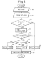
- Fig. 6 is a flow chart of a first knocking control routine executed by the CPU 554 in the processing unit 55 according to a first embodiment. This routine is executed every ignition timing calculation for each cylinder of the internal combustion engine 5, and the variables are determined for each cylinder.
- a peak VKN of the ionic current held by the peak-holding unit 33 is fetched at step 60, and signal levels VNCH and VNCL latched by the low-frequency component latching unit 341 and high-frequency component latching unit 342 respectively are fetched at step 61.
- step 62 it is determined whether or not at least either one of VNCL latched in the low-frequency component latching unit 341 and VNCH latched in the high-frequency component latching unit 342 has the level "1", that is, it is determined whether or not the level of a frequency component other than the knocking frequency band is higher than a predetermined level in the ionic current.
- step 62 determines whether the frequency component other than the knocking frequency band is higher than the predetermined level. If the determination at step 62 is negative, that is, when the frequency component other than the knocking frequency band is higher than the predetermined level, the control proceeds to step 63 where a background VBG calculation subroutine is executed. This subroutine will be explained later.
- step 64 it is determined whether or not the peak VKN of the ionic current is higher than a product of a predetermined first coefficient (K1) and the background VBG.
- K1 a predetermined first coefficient
- K2 a predetermined second coefficient
- step 65 When the determination at step 65 is affirmative, that is, when the knocking level is high, an ignition timing correction factor ⁇ TI is set to a predetermined large delay angle (-DTH) at step 66, and the control proceeds to step 69.
- step 65 When the determination at step 65 is negative, that is, when it is determined that the knocking level is low, the ignition timing correction factor ⁇ TI is set to a predetermined small delay angle (-DTL) at step 67, and the control proceeds to step 69.
- the ignition timing correction factor is set to a predetermined advancing angle LT as knocking is regarded as not occurring because an erroneous determination may be caused.
- step 64 determines whether knocking is not actually occuring. If the determination at step 64 is negative, that is, when it is determined that knocking is not actually occuring, the control proceeds to the step 68.
- An ignition timing control processing is executed at step 69 to be terminated the routine.
- the ignition timing control processing will be explained later.
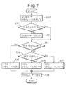
- Fig. 7 is a flow chart of a background calculation subroutine executed at step 63 of the first knocking control routine.
- An updating amount DLBG is calculated at step 630 according to the following formula, DLBG ⁇ VBG i-1 - VKN /4 where VBG i-1 is a background calculated the previous time, and the updating amount DLBG is calculated as a value one-fourth of the absolute value of a difference between the background calculated at the previous execution and a peak value VKN at this execution.
- the updating amount DLBG is limited to a predetermined upper-limit guard value GDLBG.
- step 633 and 634 it is determined whether or not the peak value VKN at this execution is larger than a product of a predetermined coefficient which is larger than 1.0 and VBG i-1 , smaller than the product and larger than VBG i-1 , or smaller than VBG i-1 .
- the background VBG is updated at step 635 according to the following formula, VBG ⁇ VBG i-1 + DLBG
- the background VBG is updated at step 636 according to the following formula, VBG ⁇ VBG i-1 + DLBG + ⁇
- the background VBG is updated at step 637 according to the following formula, VBG ⁇ VBG i-1 + DLBG - ⁇ where ⁇ is an adjustment coefficient for setting the background VBG to limit within a suitable range.
- step 638 the VBG i-1 is set to the background VBG calculated at this execution to be ready for the operation of the next execution, and this subroutine is terminated.
- Fig. 8 is a flow chart of the first ignition timing control subroutine executed at step 69 in the first knocking control routine.
- the ignition timing correction factor ⁇ TI is added to the ignition timing TI i-1 calculated at the previous execution, to calculate the ignition timing TI at this execution, TI ⁇ TI i-1 + ⁇ TI
- the ignition timing is advanced when a positive number is added and is delayed when a positive number is subtracted.
- step 693 and 694 it is determined whether or not the ignition timing TI at this execution is between the reference ignition timing TB which is the maximum advanced ignition timing and a predetermined maximum delayed ignition timing TD.
- step 693 determines whether the ignition timing TI at this execution is more advanced than the reference ignition timing TB. That is, when the ignition timing TI at this execution is more advanced than the reference ignition timing TB, the determination at step 693 is affirmative, the ignition timing TI at this execution is replaced by the reference ignition timing TB at step 695, and the control proceeds to step 697.
- step 694 determines whether the ignition timing TI at this execution is more delayed than the maximum delayed ignition timing TD. If the determination at step 694 is negative, the ignition timing TI at this execution is replaced by the maximum delayed ignition timing TD at step 696, and the control proceeds to step 697.
- the control directly proceeds to step 697.
- the ignition command signal IGT is output to the ignition coil 11 through the output I/F 553, the ignition timing TI i-1 calculated at the previous execution is updated to the ignition timing TI at this execution to be ready for the calculation of the next execution, and this subroutine is terminated.
- the detection of knocking is interrupted in order to prevent an erroneous determinating that the spike noise is regarded as knocking.
- Fig. 9 is a flow chart of a second knocking control routine and provides step 90 between step 62 and 68 of the first knocking control routine in order to solve the above-mentioned problem.
- step 90 When the determination at step 90 is affirmative, that is, when the peak value of the knocking signal is high though the noise level is higher than a predetermined level, it is regarded as the knocking is occuring, and the ignition timing is delayed at the steps 63 to 67.
- the knocking is suppressed by delaying the ignition timing and the internal combustion engine is prevented from being damaged.
- the spike noise level is detected by using the comparators 331, 332 and the latching units 341, 342 using hardware technology.
- the spike noise level can be detected by the peak-holding unit as is the knocking signal level.
- Fig. 10 is a diagram illustrating the second embodiment of a device for detecting knocking of an internal combustion engine according to the present invention, wherein a low-frequency component peak-holding unit 351 and a high-frequency component peak-holding unit 352, which are connected to the analog input I/F 551 of the processing unit 55, are provided instead of the comparators 331, 332 and the latching units 341, 342.
- Fig. 11 is a flow chart of a third knocking control routine executed by the processing unit 55 according to the second embodiment, wherein steps 61 and 62 of the second knocking control routine are replaced by steps 1101 and 1102.
- the low-frequency component peak value VNL and the high-frequency component peak value VNH which are respectively the outputs of the low-frequency component peak-holding unit 351 and high-frequency component peak-holding unit 352 are fetched through the analog input I/F 551.
- step 1102 it is determined whether or not the low-frequency component peak value VNL is higher than a predetermined low-frequency component threshold value VTHL or whether or not the high-frequency component peak value VNH is higher than a predetermined high-frequency component threshold value VTHH.
- the low-frequency component threshold value VTHL and the high-frequency component threshold value VTHH may be determined as fixed constant or as functions of the engine speed of the internal combustion engine.
- step 1102 When the determination at step 1102 is negative, it is regarded that no spike noise is occurring and, determination whether or not knocking is occuring and delaying of the ignition timing are executed at the steps 63 to 67.
- step 1102 determines whether or not the spike noise is occurring, and the control proceeds to step 90 where it is determined whether or not the knocking level is high irrespective of the generation of spike noise.
- step 1102 determines whether or not knocking is occurring is interrupted, and the control directly proceeds to step 68 to execute steps of the first knocking control routine for advancing the ignition timing.
- the noise is detected based upon both of the frequency component lower than the knocking frequency and the frequency component higher than the knocking frequency.
- the noise may be detected based upon either one of them.
- frequency components lower than the knocking frequency are affected by the disturbance of flame in the combustion chamber 501. It is therefore advantageous to detect the spike noise based upon the frequency components of higher than the knocking frequency.
- the spike noise is generated when either one of the frequency component lower than the knocking frequency or the frequency component higher than the knocking frequency is higher than a predetermined level (steps 62 and 1102).
- a predetermined level By taking into consideration the fact that the spike noise has wide frequency band component, it is also possible to judge that the spike noise is being generated when both of the frequency component lower than the knocking frequency and the frequency component higher than the knocking frequency are higher than the predetermined level.
Applications Claiming Priority (3)
| Application Number | Priority Date | Filing Date | Title |
|---|---|---|---|
| JP8233006A JP3026427B2 (ja) | 1996-09-03 | 1996-09-03 | 内燃機関のノッキング検出装置 |
| JP23300696 | 1996-09-03 | ||
| JP233006/96 | 1996-09-03 |
Publications (3)
| Publication Number | Publication Date |
|---|---|
| EP0826882A2 true EP0826882A2 (fr) | 1998-03-04 |
| EP0826882A3 EP0826882A3 (fr) | 1999-08-18 |
| EP0826882B1 EP0826882B1 (fr) | 2003-06-04 |
Family
ID=16948345
Family Applications (1)
| Application Number | Title | Priority Date | Filing Date |
|---|---|---|---|
| EP97402022A Expired - Lifetime EP0826882B1 (fr) | 1996-09-03 | 1997-08-29 | Méthode et dispositif de détection de cliquetis pour un moteur à combustion interne |
Country Status (5)
| Country | Link |
|---|---|
| US (1) | US6151954A (fr) |
| EP (1) | EP0826882B1 (fr) |
| JP (1) | JP3026427B2 (fr) |
| DE (1) | DE69722534T2 (fr) |
| ES (1) | ES2201254T3 (fr) |
Cited By (2)
| Publication number | Priority date | Publication date | Assignee | Title |
|---|---|---|---|---|
| EP1342915A3 (fr) * | 2002-03-04 | 2004-06-09 | Delphi Technologies, Inc. | Système et méthode pour la suppression de bruit impulsionnel pour processeur de signaux de courant ionique avec intégrateur |
| GB2397623A (en) * | 2002-11-01 | 2004-07-28 | Visteon Global Tech Inc | I.c. engine ignition diagnosis using ionization signal |
Families Citing this family (11)
| Publication number | Priority date | Publication date | Assignee | Title |
|---|---|---|---|---|
| DE19953710B4 (de) * | 1999-11-08 | 2010-06-17 | Robert Bosch Gmbh | Verfahren und Vorrichtung zur Meßfenster-Positionierung für die Ionenstrommessung |
| US6498490B2 (en) | 2000-06-28 | 2002-12-24 | Delphi Technologies, Inc. | Ion sense ignition bias circuit |
| JP3710064B2 (ja) * | 2003-04-07 | 2005-10-26 | 三菱電機株式会社 | 内燃機関のイオン電流検出装置 |
| US6922628B2 (en) * | 2003-11-26 | 2005-07-26 | Visteon Global Technologies, Inc. | IC engine diagnostic system using the peak and integration ionization current signals |
| JP4358198B2 (ja) | 2006-03-20 | 2009-11-04 | トヨタ自動車株式会社 | 内燃機関のノッキング判定装置 |
| FR2912185B1 (fr) * | 2007-02-05 | 2009-03-13 | Siemens Vdo Automotive Sas | Dispositif et procede de traitement de signaux de cliquetis d'un moteur a combustion interne, a reduction d'influence de bruits parasites |
| US7624627B2 (en) * | 2007-11-19 | 2009-12-01 | Caterpillar Inc. | Ion-based triple sensor |
| JP2013517427A (ja) * | 2010-01-20 | 2013-05-16 | セム アクティエボラグ | エンジンの性能を分析するための装置および方法 |
| DE102012104654B3 (de) * | 2012-05-30 | 2013-11-14 | Borgwarner Beru Systems Gmbh | Verfahren zur Klopferkennung |
| DE102014204193A1 (de) * | 2013-03-08 | 2014-09-11 | Denso Corporation | Zündvorrichtung mit einer Zündspule |
| JP6000320B2 (ja) * | 2014-11-18 | 2016-09-28 | 三菱電機株式会社 | 高周波放電点火装置 |
Citations (5)
| Publication number | Priority date | Publication date | Assignee | Title |
|---|---|---|---|---|
| US4467634A (en) * | 1981-08-26 | 1984-08-28 | Robert Bosch Gmbh | Internal combustion engine knocking sensing and recognition system |
| US4565087A (en) * | 1983-05-28 | 1986-01-21 | Robert Bosch Gmbh | Method and apparatus for recognition of knocking in an internal combustion engine |
| JPS6157830A (ja) * | 1984-08-30 | 1986-03-24 | Nec Home Electronics Ltd | 異常燃焼判定方法および装置 |
| US5220821A (en) * | 1988-05-04 | 1993-06-22 | Robert Bosch Gmbh | Method of detecting knock in internal combustion engines |
| JPH06159129A (ja) * | 1992-11-25 | 1994-06-07 | Daihatsu Motor Co Ltd | イオン電流によるノック検出方法 |
Family Cites Families (5)
| Publication number | Priority date | Publication date | Assignee | Title |
|---|---|---|---|---|
| KR950004612B1 (ko) * | 1990-06-25 | 1995-05-03 | 미쓰비시덴키가부시키가이샤 | 내연기관 실화검출방법 및 장치 |
| US5337716A (en) * | 1992-02-04 | 1994-08-16 | Mitsubishi Denki Kabushiki Kaisha | Control apparatus for internal combustion engine |
| US5483818A (en) * | 1993-04-05 | 1996-01-16 | Ford Motor Company | Method and apparatus for detecting ionic current in the ignition system of an internal combustion engine |
| JP3194680B2 (ja) * | 1994-12-15 | 2001-07-30 | 三菱電機株式会社 | 内燃機関の失火検出装置 |
| JP3477923B2 (ja) * | 1995-06-29 | 2003-12-10 | 三菱電機株式会社 | 内燃機関用燃焼状態検知装置 |
-
1996
- 1996-09-03 JP JP8233006A patent/JP3026427B2/ja not_active Expired - Fee Related
-
1997
- 1997-08-29 ES ES97402022T patent/ES2201254T3/es not_active Expired - Lifetime
- 1997-08-29 EP EP97402022A patent/EP0826882B1/fr not_active Expired - Lifetime
- 1997-08-29 DE DE69722534T patent/DE69722534T2/de not_active Expired - Fee Related
- 1997-09-02 US US08/923,744 patent/US6151954A/en not_active Expired - Fee Related
Patent Citations (5)
| Publication number | Priority date | Publication date | Assignee | Title |
|---|---|---|---|---|
| US4467634A (en) * | 1981-08-26 | 1984-08-28 | Robert Bosch Gmbh | Internal combustion engine knocking sensing and recognition system |
| US4565087A (en) * | 1983-05-28 | 1986-01-21 | Robert Bosch Gmbh | Method and apparatus for recognition of knocking in an internal combustion engine |
| JPS6157830A (ja) * | 1984-08-30 | 1986-03-24 | Nec Home Electronics Ltd | 異常燃焼判定方法および装置 |
| US5220821A (en) * | 1988-05-04 | 1993-06-22 | Robert Bosch Gmbh | Method of detecting knock in internal combustion engines |
| JPH06159129A (ja) * | 1992-11-25 | 1994-06-07 | Daihatsu Motor Co Ltd | イオン電流によるノック検出方法 |
Non-Patent Citations (2)
| Title |
|---|
| PATENT ABSTRACTS OF JAPAN vol. 010, no. 220 (P-482), 31 July 1986 & JP 61 057830 A (NEC HOME ELECTRONICS LTD), 24 March 1986 * |
| PATENT ABSTRACTS OF JAPAN vol. 018, no. 491 (M-1672), 13 September 1994 & JP 06 159129 A (DAIHATSU MOTOR CO LTD;OTHERS: 01), 7 June 1994 * |
Cited By (4)
| Publication number | Priority date | Publication date | Assignee | Title |
|---|---|---|---|---|
| EP1342915A3 (fr) * | 2002-03-04 | 2004-06-09 | Delphi Technologies, Inc. | Système et méthode pour la suppression de bruit impulsionnel pour processeur de signaux de courant ionique avec intégrateur |
| GB2397623A (en) * | 2002-11-01 | 2004-07-28 | Visteon Global Tech Inc | I.c. engine ignition diagnosis using ionization signal |
| GB2397623B (en) * | 2002-11-01 | 2005-05-11 | Visteon Global Tech Inc | Ignition diagnosis using ionization signal |
| US6998846B2 (en) * | 2002-11-01 | 2006-02-14 | Visteon Global Technologies, Inc. | Ignition diagnosis using ionization signal |
Also Published As
| Publication number | Publication date |
|---|---|
| EP0826882B1 (fr) | 2003-06-04 |
| EP0826882A3 (fr) | 1999-08-18 |
| JP3026427B2 (ja) | 2000-03-27 |
| US6151954A (en) | 2000-11-28 |
| DE69722534T2 (de) | 2004-05-13 |
| JPH1077944A (ja) | 1998-03-24 |
| DE69722534D1 (de) | 2003-07-10 |
| ES2201254T3 (es) | 2004-03-16 |
Similar Documents
| Publication | Publication Date | Title |
|---|---|---|
| US5836285A (en) | Device for controlling knocking in an internal combustion engine | |
| US5803047A (en) | Method of control system for controlling combustion engines | |
| US5777216A (en) | Ignition system with ionization detection | |
| US5979406A (en) | Knock control device for internal combustion engine | |
| EP0826882B1 (fr) | Méthode et dispositif de détection de cliquetis pour un moteur à combustion interne | |
| JP3659589B2 (ja) | 内燃機関のノック制御装置 | |
| JP3696002B2 (ja) | 内燃機関のノック制御装置 | |
| US20090078234A1 (en) | Method and system for closed loop combustion control of a lean-burn reciprocating engine using ionization detection | |
| US6145491A (en) | Method for detecting combustion knock from the ionic current in an internal combustion engine | |
| US5900536A (en) | Device for detecting knocking of an internal combustion engine | |
| US6000276A (en) | Knock detection device for an internal combustion engine avoiding erroneous knock detection | |
| JP2001073914A (ja) | 内燃機関のノック制御装置 | |
| US5929322A (en) | Device for detecting knocking in an internal combustion engine | |
| US6925374B2 (en) | Misfire detection apparatus of internal combustion engine | |
| US6185984B1 (en) | Device for detecting the knocking of an internal combustion engine | |
| EP1342915B1 (fr) | Système et méthode pour la suppression de bruit impulsionnel pour processeur de signaux de courant ionique avec intégrateur | |
| US5955664A (en) | Device for detecting a state of combustion in an internal combustion engine | |
| EP0826881B1 (fr) | Dispositif d'allumage pour moteur à combustion interne | |
| JPH1089216A (ja) | 内燃機関のノッキング制御装置 | |
| JP4006781B2 (ja) | 内燃機関のノック検出方法及び装置 | |
| JPH1113612A (ja) | 内燃機関のノッキング抑制制御装置 | |
| US6054860A (en) | Device for detecting knocking in an internal combustion engine | |
| JP3842344B2 (ja) | 内燃機関の燃焼状態検出装置 | |
| EP1092968B1 (fr) | Méthode d'analyse de combustion pour moteur à combustion interne | |
| JP2754504B2 (ja) | 内燃機関の失火検出装置 |
Legal Events
| Date | Code | Title | Description |
|---|---|---|---|
| PUAI | Public reference made under article 153(3) epc to a published international application that has entered the european phase |
Free format text: ORIGINAL CODE: 0009012 |
|
| 17P | Request for examination filed |
Effective date: 19970920 |
|
| AK | Designated contracting states |
Kind code of ref document: A2 Designated state(s): DE ES FR GB |
|
| PUAL | Search report despatched |
Free format text: ORIGINAL CODE: 0009013 |
|
| AK | Designated contracting states |
Kind code of ref document: A3 Designated state(s): AT BE CH DE DK ES FI FR GB GR IE IT LI LU MC NL PT SE |
|
| RIC1 | Information provided on ipc code assigned before grant |
Free format text: 6F 02P 9/00 A, 6F 02P 17/12 B |
|
| AKX | Designation fees paid |
Free format text: DE ES FR GB |
|
| 17Q | First examination report despatched |
Effective date: 20010703 |
|
| GRAH | Despatch of communication of intention to grant a patent |
Free format text: ORIGINAL CODE: EPIDOS IGRA |
|
| RTI1 | Title (correction) |
Free format text: METHOD AND DEVICE FOR KNOCK DETECTION IN AN INTERNAL COMBUSTION ENGINE |
|
| GRAH | Despatch of communication of intention to grant a patent |
Free format text: ORIGINAL CODE: EPIDOS IGRA |
|
| GRAA | (expected) grant |
Free format text: ORIGINAL CODE: 0009210 |
|
| AK | Designated contracting states |
Designated state(s): DE ES FR GB |
|
| REG | Reference to a national code |
Ref country code: GB Ref legal event code: FG4D |
|
| REF | Corresponds to: |
Ref document number: 69722534 Country of ref document: DE Date of ref document: 20030710 Kind code of ref document: P |
|
| ET | Fr: translation filed | ||
| REG | Reference to a national code |
Ref country code: ES Ref legal event code: FG2A Ref document number: 2201254 Country of ref document: ES Kind code of ref document: T3 |
|
| PLBE | No opposition filed within time limit |
Free format text: ORIGINAL CODE: 0009261 |
|
| STAA | Information on the status of an ep patent application or granted ep patent |
Free format text: STATUS: NO OPPOSITION FILED WITHIN TIME LIMIT |
|
| 26N | No opposition filed |
Effective date: 20040305 |
|
| PGFP | Annual fee paid to national office [announced via postgrant information from national office to epo] |
Ref country code: ES Payment date: 20070914 Year of fee payment: 11 |
|
| PGFP | Annual fee paid to national office [announced via postgrant information from national office to epo] |
Ref country code: FR Payment date: 20070808 Year of fee payment: 11 |
|
| PGFP | Annual fee paid to national office [announced via postgrant information from national office to epo] |
Ref country code: DE Payment date: 20080912 Year of fee payment: 12 |
|
| REG | Reference to a national code |
Ref country code: GB Ref legal event code: 746 Effective date: 20081024 |
|
| PGFP | Annual fee paid to national office [announced via postgrant information from national office to epo] |
Ref country code: GB Payment date: 20080903 Year of fee payment: 12 |
|
| REG | Reference to a national code |
Ref country code: FR Ref legal event code: ST Effective date: 20090430 |
|
| PG25 | Lapsed in a contracting state [announced via postgrant information from national office to epo] |
Ref country code: FR Free format text: LAPSE BECAUSE OF NON-PAYMENT OF DUE FEES Effective date: 20080901 |
|
| REG | Reference to a national code |
Ref country code: ES Ref legal event code: FD2A Effective date: 20080830 |
|
| PG25 | Lapsed in a contracting state [announced via postgrant information from national office to epo] |
Ref country code: ES Free format text: LAPSE BECAUSE OF NON-PAYMENT OF DUE FEES Effective date: 20080830 |
|
| GBPC | Gb: european patent ceased through non-payment of renewal fee |
Effective date: 20090829 |
|
| PG25 | Lapsed in a contracting state [announced via postgrant information from national office to epo] |
Ref country code: DE Free format text: LAPSE BECAUSE OF NON-PAYMENT OF DUE FEES Effective date: 20100302 |
|
| PG25 | Lapsed in a contracting state [announced via postgrant information from national office to epo] |
Ref country code: GB Free format text: LAPSE BECAUSE OF NON-PAYMENT OF DUE FEES Effective date: 20090829 |