EP0821118B1 - Gelenkarm-Markise - Google Patents
Gelenkarm-Markise Download PDFInfo
- Publication number
- EP0821118B1 EP0821118B1 EP97106767A EP97106767A EP0821118B1 EP 0821118 B1 EP0821118 B1 EP 0821118B1 EP 97106767 A EP97106767 A EP 97106767A EP 97106767 A EP97106767 A EP 97106767A EP 0821118 B1 EP0821118 B1 EP 0821118B1
- Authority
- EP
- European Patent Office
- Prior art keywords
- support pipe
- joint
- arm
- awning according
- angle
- Prior art date
- Legal status (The legal status is an assumption and is not a legal conclusion. Google has not performed a legal analysis and makes no representation as to the accuracy of the status listed.)
- Expired - Lifetime
Links
Images


Classifications
-
- E—FIXED CONSTRUCTIONS
- E04—BUILDING
- E04F—FINISHING WORK ON BUILDINGS, e.g. STAIRS, FLOORS
- E04F10/00—Sunshades, e.g. Florentine blinds or jalousies; Outside screens; Awnings or baldachins
- E04F10/02—Sunshades, e.g. Florentine blinds or jalousies; Outside screens; Awnings or baldachins of flexible canopy materials, e.g. canvas ; Baldachins
- E04F10/06—Sunshades, e.g. Florentine blinds or jalousies; Outside screens; Awnings or baldachins of flexible canopy materials, e.g. canvas ; Baldachins comprising a roller-blind with means for holding the end away from a building
- E04F10/0666—Accessories
- E04F10/0674—Accessories acting as separate supporting bar
-
- E—FIXED CONSTRUCTIONS
- E04—BUILDING
- E04F—FINISHING WORK ON BUILDINGS, e.g. STAIRS, FLOORS
- E04F10/00—Sunshades, e.g. Florentine blinds or jalousies; Outside screens; Awnings or baldachins
- E04F10/02—Sunshades, e.g. Florentine blinds or jalousies; Outside screens; Awnings or baldachins of flexible canopy materials, e.g. canvas ; Baldachins
- E04F10/06—Sunshades, e.g. Florentine blinds or jalousies; Outside screens; Awnings or baldachins of flexible canopy materials, e.g. canvas ; Baldachins comprising a roller-blind with means for holding the end away from a building
- E04F10/0611—Sunshades, e.g. Florentine blinds or jalousies; Outside screens; Awnings or baldachins of flexible canopy materials, e.g. canvas ; Baldachins comprising a roller-blind with means for holding the end away from a building with articulated arms supporting the movable end of the blind for deployment of the blind
- E04F10/0618—Sunshades, e.g. Florentine blinds or jalousies; Outside screens; Awnings or baldachins of flexible canopy materials, e.g. canvas ; Baldachins comprising a roller-blind with means for holding the end away from a building with articulated arms supporting the movable end of the blind for deployment of the blind whereby the pivot axis of the articulation is perpendicular to the roller
-
- E—FIXED CONSTRUCTIONS
- E04—BUILDING
- E04F—FINISHING WORK ON BUILDINGS, e.g. STAIRS, FLOORS
- E04F10/00—Sunshades, e.g. Florentine blinds or jalousies; Outside screens; Awnings or baldachins
- E04F10/02—Sunshades, e.g. Florentine blinds or jalousies; Outside screens; Awnings or baldachins of flexible canopy materials, e.g. canvas ; Baldachins
- E04F10/06—Sunshades, e.g. Florentine blinds or jalousies; Outside screens; Awnings or baldachins of flexible canopy materials, e.g. canvas ; Baldachins comprising a roller-blind with means for holding the end away from a building
- E04F10/0637—Sunshades, e.g. Florentine blinds or jalousies; Outside screens; Awnings or baldachins of flexible canopy materials, e.g. canvas ; Baldachins comprising a roller-blind with means for holding the end away from a building with mechanisms for adjusting the inclination of the blind
-
- Y—GENERAL TAGGING OF NEW TECHNOLOGICAL DEVELOPMENTS; GENERAL TAGGING OF CROSS-SECTIONAL TECHNOLOGIES SPANNING OVER SEVERAL SECTIONS OF THE IPC; TECHNICAL SUBJECTS COVERED BY FORMER USPC CROSS-REFERENCE ART COLLECTIONS [XRACs] AND DIGESTS
- Y10—TECHNICAL SUBJECTS COVERED BY FORMER USPC
- Y10T—TECHNICAL SUBJECTS COVERED BY FORMER US CLASSIFICATION
- Y10T403/00—Joints and connections
- Y10T403/32—Articulated members
- Y10T403/32254—Lockable at fixed position
- Y10T403/32262—At selected angle
- Y10T403/32319—At selected angle including pivot stud
- Y10T403/32368—At selected angle including pivot stud including radial interengaging tongue and slot or serrations
Definitions
- the invention is directed to an articulated arm awning according to the preamble of claim 1
- Articulated arm awnings are available as cassette awnings or open Known awnings. Conventionally, especially with open awnings an inclination adjustment of the articulated arms relative to the mounting wall or to the floor in that a tilt adjustment arrangement on each articulated arm is provided. Accordingly, the conventional ones Constructions relatively complex and expensive.
- Such an awning is known from CH-A-517 230.
- the object of the invention is an articulated arm awning of the type mentioned in such a way that the Tilt adjustment is simplified in design and regardless of the given inclination constant, defined entry conditions are.
- the support tube in is essentially round with a longitudinal groove that each mounting bracket has a bearing section on which the support tube in the bearing section can be partially inserted in a form-fitting manner, that a holding section of the mounting bracket on the support tube partially detachably overlaps the top, and that Support tube a recess at least in the area of the mounting brackets has a height adjustable relative to the bearing section Operating and locking cam engages in such a way that by the height adjustment of the cam, the support tube can be pivoted and thus the angle of inclination the articulated arms are adjustable.
- the cam has a parallel guide section has that parallel in the bearing section of the mounting bracket is guided, and which is provided with a threaded bore into one engages with its head on the bearing portion supporting screw.
- the set screw can be approximately parallel from the bottom be used for the wall contact surface of the mounting bracket, so that a easy actuation from below is guaranteed.
- the recess of the support tube can advantageously be a groove-like, in particular be semicircular recess, the outer end of the cam, which is shaped accordingly, in this groove can intervene.
- a bearing section of the Fastening brackets or support tube holders the support tube essentially encompasses and has angularly offset threaded holes, in which depending on the desired angle setting one in the at least one longitudinal groove of the support tube engaging locking screw can be screwed in.
- Words will be one depending on the desired angle setting the existing threaded holes for screwing in the locking screw selected.
- the support tube along its circumference offset a plurality of longitudinal grooves or protrusions having. Accordingly, only a single threaded hole can then be used be provided and the support tube is pivoted accordingly.
- an articulated arm bracket surrounds each also the U-shaped support tube, using a set screw, which engages in the thread of an adjusting cam, one in the groove of the Carrier tube engaging cam approach shiftable and thus an inclination adjustment is feasible
- a support tube 1 is shown, which by means of two mounting brackets 2 can be attached to the wall.
- the articulated arms are attached
- a cloth winding shaft is not shown in the drawing.
- Storage attached to the support tube 1, from which the awning cloth the front edge of which is attached to a drop profile when the articulated arms are extended is pulled off by pivoting the articulated arms on the outsides attack the drop profile. Since the articulated arms rotate with are connected to the support tube 1, corresponds to a pivoting of the support tube 1 about its longitudinal axis 3 a change in inclination of the articulated arms.
- the storage and pivoting of the support tube 1 is described in more detail below:
- the fastening bracket 2 has a plate-like wall fastening section 4 with holes 5 for fastening screws. From the bottom A bearing section extends at the end of the wall fastening section 4 6 away to the outside, on the outside of a threaded hole 7 for one Retaining screw 8 is formed between the fastening section 4 and Bore 7 is the bearing section 6 with a part-circular recess 9 provided, the radius of which corresponds to the radius of the support tube 1 accordingly can during the assembly process, the support tube 1 on this bearing section 6 are initially filed.
- a holding section 10 of the mounting bracket 2 has an approach 11, which positively fits into a corresponding one Recess 12 on a projection 13 of the fastening section 4 engages.
- the holding section 10 also has a recess 14 on, which is partially circular in cross section with a corresponding Radius as the support tube 1 is formed and accordingly Can overlap support tube 1 from above.
- a threaded bore 15 is formed, which with the threaded bore 7 of the bearing section 6 is aligned so that a retaining screw 8 can be screwed in from below, against the holding section 10 clamped the bearing section 6 and thereby fixes the support tube 1.
- the support tube has a lateral recess 16 in the form of a cross section partly circular groove into which a correspondingly shaped Engages cam 17, which is followed by a parallel guide section 18, which runs approximately perpendicular to the longitudinal extent of the cam and in a corresponding parallel guide section 19 of the fastening section 4 parallel to the wall contact surface 20 of the mounting bracket 2 is performed.
- the parallel guide section 18 that with the cam 17 is connected has a threaded bore into which an adjusting screw 21 engages, whose head 22 is at the bottom 23 of a blind hole supports, and screwed from the bottom into the mounting section 4 becomes.
- the cam 17th is height adjustable via the adjusting screw 21.
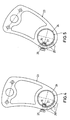
- the support tube 1 is pivoted into the groove-shaped recess 16, starting from the position shown in Fig. 1 clockwise to the right by 15 ° in the position shown in Fig. 2 and by a total 30 ° in the position shown in Fig. 3.
- a support tube holder 23 provided with a circular recess 24 for receiving the Support tube 1.
- Angularly offset around the recess 24 are threaded holes 25 arranged, into which a locking screw 26 can be screwed is, whose inner end 27 engages in a groove 16 of the support tube 1.
- two arm brackets 28 are arranged, which are U-shaped are designed and the support tube over an angle of Grip around 180 °.
- a pivot axis 31 an inner articulated arm section 32 is pivotably mounted, which in turn can be pivoted with an outer articulated arm section 33 connected is.
- a screw 34 starts from one U-leg 29 in a threaded bore 25 on the opposite U-leg 30 in and between the two U-legs 29, 30 is a spacer sleeve 35 provided.
- a plurality of threaded holes 37 are arranged at an angle, in which a locking screw 38 can be inserted, the inner end 39 in the Groove 16 of the support tube 1 engages.
- the comparison of FIGS. 6 and 7 shows that depending on the selection of one of the threaded holes 37 an inclination setting can be made.
- FIGS. 8 and 9 enables either an inclination adjustment the articulated arms relative to the support tube when stationary Support tube or a superimposed tilt adjustment on the one hand of the Support tube in the manner described above and an additional inclination adjustment the articulated arms, so that overall very large adjustment ranges or very fine gradations can be realized.
- Arm consoles are similar to the embodiment according to FIGS. 6 and 7 40 is provided, on which the inner articulated arm section 32 by one Pivot bearing bolts are pivotally mounted in the form of a screw 34.
- the arm consoles 40 are U-shaped, in two parts, a part 41 with a bent portion 42 the support tube engages positively and includes a U-leg 43 and the other Part 44 comprises the second U-leg 45, both U-legs 43, 45 can be connected by means of a screw 46.
- a hook extension 47 is arranged, which has a corresponding one Projection 48 of the other part 43 engages positively.
Description
- Fig. 1 bis 3
- eine Seitenansicht (teilweise geschnitten) des Tragrohr-Lagerbereiches bei verschiedenen Neigungseinstellungen bei einer ersten Ausführungsform,
- Fig. 4 und 5
- eine schematische Ansicht einer zweiten Ausführungsform,
- Fig. 6 und 7
- eine dritte Ausführungsform, bei welcher die Gelenkarme relativ zu dem Tragrohr verschwenkt werden, und
- Fig. 8 und 9
- eine weitere Ausführungsform in verschiedenen Neigungseinstellungen.
Claims (14)
- Gelenkarm-Markise umfassend zwei an einem im wesentlichen runden Tragrohr (1) angeordnete Gelenkarme (32, 33) und Befestigungskonsolen (2), wobei das Tragrohr (1) über diese Befestigungskonsolen (2) mit einer Gebäudewand verbindbar ist, und wobei Einrichtungen zur Neigungsverstellung der Gelenkarme (32, 33) vorgesehen sind, dadurch gekennzeichnet, daß das Tragrohr (1) mit wenigstens einer Längsnut ausgebildet ist, in welche ein Feststellelement in Form eines Nockens (17), oder einer Feststellschraube zur Neigungsverstellung eingreift.
- Gelenkarm-Markise nach Anspruch 1, dadurch gekennzeichnet, daß jede Befestigungskonsole (2) einen Lagerabschnitt (6) aufweist, auf welchen das Tragrohr (1) in den Lagerabschnitt (6) teilweise formschlüssig eingreifend aufsetzbar ist,
daß ein Halteabschnitt (10) der Befestigungskonsole (2) das aufgesetzte Tragrohr (1) an der Oberseite teilweise formschlüssig lösbar übergreift und daß dasTragrohr(1) wenigstens im Bereich der Befestigungskonsolen (2) eine Ausnehmung (16) anfweist, in die ein relativ zum Lagerabschnitt (6) höhenverstellbarer Betätigungs- und Arretiernocken (17) derart eingreift, daß durch die Höhenverstellung des Nockens (17) das Tragrohr (1) verschwenkbar und damit der Neigungswinkel der Gelenkarme (32, 33) einstellbar ist. - Gelenkarm-Markise nach Anspruch 1, dadurch gekennzeichnet, daß der Nocken (17) einen Parallelführungsabschnitt (18) aufweist, der im Lagerabschnitt (6) parallel geführt ist, und welcher mit einer Gewindebohrung (15) versehen ist, in die eine sich mit ihrem Kopf (22) an dem Lagerabschnitt (6) abstützende Stellschraube (21) eingreift.
- Gelenkarm-Markise nach Anspruch 2, dadurch gekennzeichnet, daß die Stellschraube (21) von der Unterseite her etwa parallel zur Wandanlagefläche (20) der Befestigungskonsole (2) eingreift.
- Gelenkarm-Markise nach Anspruch 1, dadurch gekennzeichnet, daß die Ausnehmung (16) des Tragrohrs (1) als nutartige, insbesondere halbkreisförmige Vertiefung ausgebildet ist und das Außenende des Nockens (17) korrespondierend geformt in diese Nut formschlüssig eingreift.
- Gelenkarm-Markise nach Anspruch 1, dadurch gekennzeichnet, daß der Halteabschnitt (10) mit seinem einen Ende über einen Ansatz (11) formschlüssig in eine korrespondierende Ausnehmung (12) der Befestigungskonsole (2) eingreift und an seinem anderen Ende eine Gewindebohrung (15) zum Eingriff einer stellschraube (21) aufweist, die eine fluchtende Gewindebohrung (15) an der Außenseite des Lagerabschnitts (6) durchsetzt.
- Gelenkarm-Markise nach Anspruch 1, dadurch gekennzeichnet, daß ein Lagerabschnitt der Befestigungskonsolen bzw. von Tragrohrhaltern (23) das Tragrohr (1) im wesentlichen umgreift und winkelversetzte Gewindebohrungen (25) aufweist, in welche je nach gewünschter Winkeleinstellung eine in die wenigstens eine Längsnut des Tragrohrs (1) eingreifende Feststellschraube (26) einschraubbar ist.
- Gelenkarm-Markise nach Anspruch 7, dadurch gekennzeichnet, daß das Tragrohr (1) längs seines Umfanges winkelversetzt eine Mehrzahl von Längsnuten (16) aufweist.
- Gelenkarm-Markise nach Anspruch 1, dadurch gekennzeichnet, daß am Tragrohr (1) wenigstens abschnittsweise formschlüssig umgreifende Gelenkarm-Konsolen (28) vorgesehen sind, welche winkelversetzte Gewindebohrungen (37) zum Einsetzen einer Feststellschraube (38) aufweisen, die in die wenigstens eine Längsnut (16) des Tragrohrs (1) zur Neigungseinstellung der Gelenkarme (32, 33) eingreift.
- Gelenkarm-Markise nach Anspruch 9, dadurch gekennzeichnet, daß das Tragrohr (1) längs seines Umfanges winkelversetzt eine Mehrzahl von Längsnuten (16) aufweist.
- Gelenkarm-Markise nach Anspruch 1, dadurch gekennzeichnet, daß das Tragrohr (1) längs seines Umfanges eine oder mehrere Längsvorwölbungen aufweist, welchen korrespondierende Arretierausnehmungen zugeordnet sind.
- Gelenkarm-Markise nach Anspruch 11, dadurch gekennzeichnet, daß der Nocken (17) zur Neigungsverstellung eine zur Tragrohrvorwölbung korrespondierende Nut aufweist.
- Gelenkarm-Markise nach Anspruch 1, dadurch gekennzeichnet, daß jeweils eine Armkonsole (40) das Tragrohr (1) U-Bügelförmig umgreift, wobei an der Gelenkarmkonsole eine sich an dieser abstützende Stellschraube vorgesehen ist, mittels derer ein Verstellnocken verstellbar ist, dessen Nockenansatz in die Nut (16) des Tragrohrs (1) eingreift.
- Gelenkarmmarkise nach Anspruch 1 und 13, dadurch gekennzeichnet, daß sowohl das Tragrohr (1) relativ zu seinen Befestigungskonsolen (2) als auch die Gelenkarme (32, 33) relativ zu dem Tragrohr (1) neigungsverstellbar sind.
Applications Claiming Priority (2)
| Application Number | Priority Date | Filing Date | Title |
|---|---|---|---|
| DE29612904U | 1996-07-25 | ||
| DE29612904U DE29612904U1 (de) | 1996-07-25 | 1996-07-25 | Gelenkarm-Markise |
Publications (3)
| Publication Number | Publication Date |
|---|---|
| EP0821118A2 EP0821118A2 (de) | 1998-01-28 |
| EP0821118A3 EP0821118A3 (de) | 1999-10-20 |
| EP0821118B1 true EP0821118B1 (de) | 2003-07-23 |
Family
ID=8026973
Family Applications (1)
| Application Number | Title | Priority Date | Filing Date |
|---|---|---|---|
| EP97106767A Expired - Lifetime EP0821118B1 (de) | 1996-07-25 | 1997-04-24 | Gelenkarm-Markise |
Country Status (7)
| Country | Link |
|---|---|
| US (1) | US5924466A (de) |
| EP (1) | EP0821118B1 (de) |
| JP (1) | JP3130492B2 (de) |
| AT (1) | ATE245747T1 (de) |
| DE (2) | DE29612904U1 (de) |
| DK (1) | DK0821118T3 (de) |
| ES (1) | ES2202517T3 (de) |
Cited By (1)
| Publication number | Priority date | Publication date | Assignee | Title |
|---|---|---|---|---|
| EP3000950A1 (de) | 2014-09-29 | 2016-03-30 | Schmitz-Werke GmbH + Co. KG | Wandkonsole für eine markise mit neigungsverstellung |
Families Citing this family (12)
| Publication number | Priority date | Publication date | Assignee | Title |
|---|---|---|---|---|
| DE10001762A1 (de) * | 2000-01-18 | 2001-07-19 | Schmitz Werke | Konsole zur Befestigung des Tragrohrs einer Gelenkarm-Markise |
| DE10001756A1 (de) * | 2000-01-18 | 2001-07-19 | Schmitz Werke | Gelenkarm-Markise mit einer Abdeckung, insbesondere Kassetten-Markise |
| DE10004197A1 (de) * | 2000-02-01 | 2001-08-02 | Dolenz Gollner Gmbh | Cassettenmarkise |
| DE10061819A1 (de) * | 2000-12-12 | 2002-06-13 | Schmitz Werke | Gelenkarm-Markise |
| DE10243822C1 (de) * | 2002-09-20 | 2003-11-13 | Mhz Sonnenschutztech Gmbh | Tragrohrmarkise |
| US6792993B1 (en) * | 2002-12-07 | 2004-09-21 | Wilson G. Forbes | Awning travel lock |
| US20060086047A1 (en) * | 2004-10-26 | 2006-04-27 | Heitel Robert G | Adjustable pitch mounting bracket for lateral arm awnings |
| WO2008152152A1 (es) * | 2007-06-11 | 2008-12-18 | Llaza, Sa | Conjunto de soporte para toldo con dispositivo de regulación de inclinación |
| USD735889S1 (en) | 2013-06-14 | 2015-08-04 | Schmitz-Werke Gmbh + Co. Kg | Awning holder |
| CN105083143A (zh) * | 2014-09-18 | 2015-11-25 | 宁波万汇窗篷用品有限公司 | 遮阳篷装置 |
| CN108166688B (zh) | 2017-05-08 | 2019-11-05 | 宁波万汇休闲用品有限公司 | 遮蔽篷装置 |
| EP3495582A1 (de) | 2017-12-08 | 2019-06-12 | Activa Awning Inc. | Markisenvorrichtung |
Family Cites Families (20)
| Publication number | Priority date | Publication date | Assignee | Title |
|---|---|---|---|---|
| US2144827A (en) * | 1936-02-17 | 1939-01-24 | Astrup Company | Lateral arm awning |
| US2890853A (en) * | 1956-01-03 | 1959-06-16 | Azzo Errol P D | Awning support |
| US2880956A (en) * | 1956-04-05 | 1959-04-07 | Astrup Company | Lateral awning arm bracket with horizontal adjustment |
| FR2046040A5 (de) * | 1969-05-19 | 1971-03-05 | Choffel Marius | |
| CH517230A (de) * | 1970-04-23 | 1971-12-31 | Stromeyer & Co Gmbh L | Markise |
| DE7232630U (de) * | 1971-12-28 | 1972-11-30 | Choffel M | Aufrollbare Markise |
| DE2408060A1 (de) * | 1974-02-20 | 1975-08-28 | Ade Werk Gmbh | Markisenabdeckung |
| EP0000915B1 (de) * | 1977-08-19 | 1981-06-03 | WEINOR Dieter Weiermann GmbH & Co. | Kippgelenk für Markisen |
| DE2753955C2 (de) * | 1977-12-03 | 1984-02-23 | Bernhard Spettmann, Metallverarbeitung, 2350 Neumünster | Gelenkarmmarkise |
| DE2753959C2 (de) * | 1977-12-03 | 1982-12-16 | Rolladen-Spettmann, Holsteiner Rolladen- u. Markisenfabrik, Ing. Bernhard Spettmann, 2350 Neumünster | Gelenkarmmarkise |
| DE2834486C2 (de) * | 1978-08-07 | 1984-06-20 | Bernhard Spettmann, Metallverarbeitung, 2350 Neumünster | Gelenkarmmarkise |
| US4599998A (en) * | 1984-06-01 | 1986-07-15 | Castillo James D | Adjustable polycentric orthopedic appliance hinge |
| DE3422449A1 (de) * | 1984-06-16 | 1985-12-19 | Paul Voss Gmbh U. Co, 5950 Finnentrop | Armlager fuer eine gelenkarmmarkise |
| GB2227520B (en) * | 1988-10-26 | 1992-08-12 | Protectair Ltd | Adjustable hinge device |
| DE9000939U1 (de) * | 1990-01-29 | 1990-04-12 | Warema Renkhoff Gmbh & Co Kg, 8772 Marktheidenfeld, De | |
| DE4106032A1 (de) * | 1990-05-09 | 1991-11-14 | Viktor Lohausen | Gelenkarmmarkise |
| US5427168A (en) * | 1991-01-28 | 1995-06-27 | Lohausen; Viktor | Mounting for articulated-arm awnings |
| US5119867A (en) * | 1991-03-21 | 1992-06-09 | Lukos Stephen P | Arm structure for awning support system |
| CA2128018A1 (en) * | 1992-01-13 | 1993-07-22 | Viktor Lohausen | Fitting section for accepting and holding various securing and/or moving components of an awning |
| US5381814A (en) * | 1992-12-01 | 1995-01-17 | Brandon; Steven L. | Canopy for mounting on a vehicle luggage rack |
-
1996
- 1996-07-25 DE DE29612904U patent/DE29612904U1/de not_active Expired - Lifetime
-
1997
- 1997-04-24 ES ES97106767T patent/ES2202517T3/es not_active Expired - Lifetime
- 1997-04-24 EP EP97106767A patent/EP0821118B1/de not_active Expired - Lifetime
- 1997-04-24 DK DK97106767T patent/DK0821118T3/da active
- 1997-04-24 AT AT97106767T patent/ATE245747T1/de active
- 1997-04-24 DE DE59710454T patent/DE59710454D1/de not_active Expired - Lifetime
- 1997-07-11 US US08/893,616 patent/US5924466A/en not_active Expired - Lifetime
- 1997-07-18 JP JP09194207A patent/JP3130492B2/ja not_active Expired - Fee Related
Cited By (2)
| Publication number | Priority date | Publication date | Assignee | Title |
|---|---|---|---|---|
| EP3000950A1 (de) | 2014-09-29 | 2016-03-30 | Schmitz-Werke GmbH + Co. KG | Wandkonsole für eine markise mit neigungsverstellung |
| DE102014219680A1 (de) | 2014-09-29 | 2016-03-31 | Schmitz-Werke Gmbh + Co. Kg | Wandkonsole für eine Markise mit Neigungsverstellung |
Also Published As
| Publication number | Publication date |
|---|---|
| DE59710454D1 (de) | 2003-08-28 |
| DE29612904U1 (de) | 1996-09-26 |
| JPH1077727A (ja) | 1998-03-24 |
| DK0821118T3 (da) | 2003-11-17 |
| EP0821118A2 (de) | 1998-01-28 |
| EP0821118A3 (de) | 1999-10-20 |
| ES2202517T3 (es) | 2004-04-01 |
| US5924466A (en) | 1999-07-20 |
| ATE245747T1 (de) | 2003-08-15 |
| JP3130492B2 (ja) | 2001-01-31 |
Similar Documents
| Publication | Publication Date | Title |
|---|---|---|
| EP2222202B1 (de) | Schubkasten mit Frontverstellung | |
| EP0821118B1 (de) | Gelenkarm-Markise | |
| EP1613890B1 (de) | Standfuss | |
| WO2010054836A2 (de) | Klemmhalterung | |
| EP1327036B1 (de) | Markise mit neigungsverstellung | |
| DE4241773A1 (de) | ||
| EP2313692B1 (de) | Hausgerät | |
| EP0386342A1 (de) | Flügeltür, insbesondere in einer Duschabtrennung | |
| EP0808961B1 (de) | Gelenkarmmarkise | |
| EP1215348B1 (de) | Gelenkarm-Markise | |
| EP0186742B1 (de) | Kippgelenk für eine Kassettenmarkise | |
| WO2004094749A1 (de) | An einer unterkonstruktion befestige halterung für platten | |
| DE3141158A1 (de) | Fuehrungsvorrichtung fuer einen ein- und ausfahrbaren einsatz im korpus einer dentaleinrichtung | |
| EP1342864B1 (de) | Neigungsverstelleinrichtung für Gelenkarmmarkise | |
| DE2834486A1 (de) | Verstellbare halterung fuer die arme einer gelenkarm-markise | |
| EP2740872B1 (de) | Zur verdeckten anordnung vorgesehenes ecklager | |
| EP3922869A1 (de) | Anschlussvorrichtung zum befestigen an einem hohlprofil sowie stabilisierungsset und stabilisierungsanordnung | |
| EP4045342A1 (de) | System zum achsjustieren, exzenterelement für ein solches system und verfahren zum achsjustieren | |
| DE4444162C2 (de) | Umfassungszarge | |
| EP0439795B1 (de) | Duschabtrennung | |
| DE2214170C3 (de) | Halterung für den Auslösehebel einer Teleskopsäule in einem blockierbaren Hubaggregat fur höhenverstellbare Möbel, vorzugsweise Stühle | |
| DE10216478A1 (de) | Gelenkarm-Markise | |
| EP0617191B1 (de) | Führungsschienenanordnung für eine Wintergartenmarkise o. dgl. | |
| EP0087070A2 (de) | Leuchtengehäuse | |
| DE19950908A1 (de) | Monitorträger für Flachbildschirme |
Legal Events
| Date | Code | Title | Description |
|---|---|---|---|
| PUAI | Public reference made under article 153(3) epc to a published international application that has entered the european phase |
Free format text: ORIGINAL CODE: 0009012 |
|
| AK | Designated contracting states |
Kind code of ref document: A2 Designated state(s): AT BE CH DE DK ES FR GB IT LI NL SE |
|
| AX | Request for extension of the european patent |
Free format text: SI PAYMENT 970425 |
|
| PUAL | Search report despatched |
Free format text: ORIGINAL CODE: 0009013 |
|
| AK | Designated contracting states |
Kind code of ref document: A3 Designated state(s): AT BE CH DE DK ES FR GB IT LI NL SE |
|
| AX | Request for extension of the european patent |
Free format text: SI PAYMENT 19970425 |
|
| 17P | Request for examination filed |
Effective date: 19990928 |
|
| AKX | Designation fees paid |
Free format text: AT BE CH DE DK ES FR GB IT LI NL SE |
|
| AXX | Extension fees paid |
Free format text: SI PAYMENT 19970425 |
|
| 17Q | First examination report despatched |
Effective date: 20011210 |
|
| GRAH | Despatch of communication of intention to grant a patent |
Free format text: ORIGINAL CODE: EPIDOS IGRA |
|
| GRAH | Despatch of communication of intention to grant a patent |
Free format text: ORIGINAL CODE: EPIDOS IGRA |
|
| GRAA | (expected) grant |
Free format text: ORIGINAL CODE: 0009210 |
|
| AK | Designated contracting states |
Designated state(s): AT BE CH DE DK ES FR GB IT LI NL SE |
|
| AX | Request for extension of the european patent |
Extension state: SI |
|
| REG | Reference to a national code |
Ref country code: GB Ref legal event code: FG4D Free format text: NOT ENGLISH |
|
| REG | Reference to a national code |
Ref country code: CH Ref legal event code: EP |
|
| GBT | Gb: translation of ep patent filed (gb section 77(6)(a)/1977) |
Effective date: 20030723 |
|
| REF | Corresponds to: |
Ref document number: 59710454 Country of ref document: DE Date of ref document: 20030828 Kind code of ref document: P |
|
| REG | Reference to a national code |
Ref country code: SE Ref legal event code: TRGR |
|
| REG | Reference to a national code |
Ref country code: DK Ref legal event code: T3 |
|
| REG | Reference to a national code |
Ref country code: ES Ref legal event code: FG2A Ref document number: 2202517 Country of ref document: ES Kind code of ref document: T3 |
|
| ET | Fr: translation filed | ||
| PLBE | No opposition filed within time limit |
Free format text: ORIGINAL CODE: 0009261 |
|
| STAA | Information on the status of an ep patent application or granted ep patent |
Free format text: STATUS: NO OPPOSITION FILED WITHIN TIME LIMIT |
|
| 26N | No opposition filed |
Effective date: 20040426 |
|
| REG | Reference to a national code |
Ref country code: FR Ref legal event code: PLFP Year of fee payment: 19 |
|
| REG | Reference to a national code |
Ref country code: FR Ref legal event code: PLFP Year of fee payment: 20 |
|
| PGFP | Annual fee paid to national office [announced via postgrant information from national office to epo] |
Ref country code: CH Payment date: 20160310 Year of fee payment: 20 |
|
| PGFP | Annual fee paid to national office [announced via postgrant information from national office to epo] |
Ref country code: NL Payment date: 20160422 Year of fee payment: 20 |
|
| PGFP | Annual fee paid to national office [announced via postgrant information from national office to epo] |
Ref country code: GB Payment date: 20160422 Year of fee payment: 20 Ref country code: DE Payment date: 20151219 Year of fee payment: 20 Ref country code: ES Payment date: 20160422 Year of fee payment: 20 |
|
| PGFP | Annual fee paid to national office [announced via postgrant information from national office to epo] |
Ref country code: IT Payment date: 20160422 Year of fee payment: 20 Ref country code: FR Payment date: 20160422 Year of fee payment: 20 Ref country code: AT Payment date: 20160311 Year of fee payment: 20 Ref country code: SE Payment date: 20160422 Year of fee payment: 20 Ref country code: DK Payment date: 20160425 Year of fee payment: 20 Ref country code: BE Payment date: 20160422 Year of fee payment: 20 |
|
| REG | Reference to a national code |
Ref country code: DE Ref legal event code: R071 Ref document number: 59710454 Country of ref document: DE |
|
| REG | Reference to a national code |
Ref country code: NL Ref legal event code: MK Effective date: 20170423 |
|
| REG | Reference to a national code |
Ref country code: DK Ref legal event code: EUP Effective date: 20170424 |
|
| REG | Reference to a national code |
Ref country code: CH Ref legal event code: PL |
|
| REG | Reference to a national code |
Ref country code: GB Ref legal event code: PE20 Expiry date: 20170423 |
|
| REG | Reference to a national code |
Ref country code: AT Ref legal event code: MK07 Ref document number: 245747 Country of ref document: AT Kind code of ref document: T Effective date: 20170424 |
|
| PG25 | Lapsed in a contracting state [announced via postgrant information from national office to epo] |
Ref country code: GB Free format text: LAPSE BECAUSE OF EXPIRATION OF PROTECTION Effective date: 20170423 |
|
| REG | Reference to a national code |
Ref country code: ES Ref legal event code: FD2A Effective date: 20180508 |
|
| PG25 | Lapsed in a contracting state [announced via postgrant information from national office to epo] |
Ref country code: ES Free format text: LAPSE BECAUSE OF EXPIRATION OF PROTECTION Effective date: 20170425 |