EP0820882B1 - Radialer Luftreifen - Google Patents
Radialer Luftreifen Download PDFInfo
- Publication number
- EP0820882B1 EP0820882B1 EP97112768A EP97112768A EP0820882B1 EP 0820882 B1 EP0820882 B1 EP 0820882B1 EP 97112768 A EP97112768 A EP 97112768A EP 97112768 A EP97112768 A EP 97112768A EP 0820882 B1 EP0820882 B1 EP 0820882B1
- Authority
- EP
- European Patent Office
- Prior art keywords
- bead
- tire
- pneumatic radial
- reinforcing layer
- height
- Prior art date
- Legal status (The legal status is an assumption and is not a legal conclusion. Google has not performed a legal analysis and makes no representation as to the accuracy of the status listed.)
- Expired - Lifetime
Links
Images

Classifications
-
- B—PERFORMING OPERATIONS; TRANSPORTING
- B60—VEHICLES IN GENERAL
- B60C—VEHICLE TYRES; TYRE INFLATION; TYRE CHANGING; CONNECTING VALVES TO INFLATABLE ELASTIC BODIES IN GENERAL; DEVICES OR ARRANGEMENTS RELATED TO TYRES
- B60C15/00—Tyre beads, e.g. ply turn-up or overlap
- B60C15/06—Flipper strips, fillers, or chafing strips and reinforcing layers for the construction of the bead
-
- B—PERFORMING OPERATIONS; TRANSPORTING
- B60—VEHICLES IN GENERAL
- B60C—VEHICLE TYRES; TYRE INFLATION; TYRE CHANGING; CONNECTING VALVES TO INFLATABLE ELASTIC BODIES IN GENERAL; DEVICES OR ARRANGEMENTS RELATED TO TYRES
- B60C9/00—Reinforcements or ply arrangement of pneumatic tyres
- B60C9/18—Structure or arrangement of belts or breakers, crown-reinforcing or cushioning layers
- B60C9/20—Structure or arrangement of belts or breakers, crown-reinforcing or cushioning layers built-up from rubberised plies each having all cords arranged substantially parallel
- B60C9/22—Structure or arrangement of belts or breakers, crown-reinforcing or cushioning layers built-up from rubberised plies each having all cords arranged substantially parallel the plies being arranged with all cords disposed along the circumference of the tyre
-
- Y—GENERAL TAGGING OF NEW TECHNOLOGICAL DEVELOPMENTS; GENERAL TAGGING OF CROSS-SECTIONAL TECHNOLOGIES SPANNING OVER SEVERAL SECTIONS OF THE IPC; TECHNICAL SUBJECTS COVERED BY FORMER USPC CROSS-REFERENCE ART COLLECTIONS [XRACs] AND DIGESTS
- Y10—TECHNICAL SUBJECTS COVERED BY FORMER USPC
- Y10T—TECHNICAL SUBJECTS COVERED BY FORMER US CLASSIFICATION
- Y10T152/00—Resilient tires and wheels
- Y10T152/10—Tires, resilient
- Y10T152/10495—Pneumatic tire or inner tube
- Y10T152/10765—Characterized by belt or breaker structure
- Y10T152/10783—Reinforcing plies made up from wound narrow ribbons
-
- Y—GENERAL TAGGING OF NEW TECHNOLOGICAL DEVELOPMENTS; GENERAL TAGGING OF CROSS-SECTIONAL TECHNOLOGIES SPANNING OVER SEVERAL SECTIONS OF THE IPC; TECHNICAL SUBJECTS COVERED BY FORMER USPC CROSS-REFERENCE ART COLLECTIONS [XRACs] AND DIGESTS
- Y10—TECHNICAL SUBJECTS COVERED BY FORMER USPC
- Y10T—TECHNICAL SUBJECTS COVERED BY FORMER US CLASSIFICATION
- Y10T152/00—Resilient tires and wheels
- Y10T152/10—Tires, resilient
- Y10T152/10495—Pneumatic tire or inner tube
- Y10T152/10819—Characterized by the structure of the bead portion of the tire
- Y10T152/10828—Chafer or sealing strips
-
- Y—GENERAL TAGGING OF NEW TECHNOLOGICAL DEVELOPMENTS; GENERAL TAGGING OF CROSS-SECTIONAL TECHNOLOGIES SPANNING OVER SEVERAL SECTIONS OF THE IPC; TECHNICAL SUBJECTS COVERED BY FORMER USPC CROSS-REFERENCE ART COLLECTIONS [XRACs] AND DIGESTS
- Y10—TECHNICAL SUBJECTS COVERED BY FORMER USPC
- Y10T—TECHNICAL SUBJECTS COVERED BY FORMER US CLASSIFICATION
- Y10T152/00—Resilient tires and wheels
- Y10T152/10—Tires, resilient
- Y10T152/10495—Pneumatic tire or inner tube
- Y10T152/10819—Characterized by the structure of the bead portion of the tire
- Y10T152/10837—Bead characterized by the radial extent of apex, flipper or chafer into tire sidewall
Definitions
- the present invention relates to a pneumatic radial tire in which excellent stability and controllability are provided and a large amount of road noise can be reduced at the traveling time of a vehicle.
- road noise is caused by the tire at the traveling time of a vehicle picking up irregularities on a road surface.
- the resultant vibration is conveyed to the interior of a vehicle, thereby causing the air to vibrate at the interior of the vehicle.
- a method in which the whole portion or the widthwise direction end portions of a crossing belt layer is/are held by a reinforcing layer which is made of rubber-coated cords such as nylon cords which are disposed in the circumferential direction of a tire so that the rigidity of the aforementioned belt layer in the circumferential direction thereof can be reinforced.
- a ribbon-shaped strip is formed by rubber-coating a nylon cord or a plurality of nylon cords which are disposed in parallel to each other, and is wound around a tire substantially in the circumferential direction thereof.
- a green tire to which a tread member unvulcanized is attached is vulcanized on the above resulting tire so that a tire as a product is manufactured.
- nylon cords generally show young's modulus which is relatively low at the range of temperature depending upon the use conditions of a tire (a large elongation 4.2% was resulted under load of 1.4 g/d at the temperature of 50 ⁇ 5°C), it is impossible to improve road noise to the desired level.
- nylon cords tend to generate a flat spot on a tire, especially in winter, when a vehicle runs after having parked for a long time, abnormal vibration may be caused.
- the angle formed between the cords and a crossing belt layer (especially, a belt layer which is made of steel cords) which is positioned inwardly in the radial direction of a tire, i.e., the angle formed at the time when a green tire is inflated due to an internal vulcanization pressure, can be prevented from being changed so that a desirable angle changes cannot be provided.
- the belt reinforcing layer and the belt layer are displaced from each other, thereby affecting the uniformity of a tire adversely, thereby causing problems in noise and stability and controllability of a tire.
- the fiber cords forming the belt reinforcing layer needs to have a 1.5 to 6.0% elongation under load of 0.7g/d at the temperature received by the fiber cord at the time of vulcanizing forming of a tire, i.e., 170 ⁇ 5°C.
- a vulcanization forming die is inserted into a green tire, an internal pressure is filled in the green tire, and the green tire is pressed onto the internal surface of a forming die, it is important to keep respective portions of a tread, whose elongation is unfixed, in close contact with the forming die so that the tread elongates sufficiently.
- the cords used to form the belt reinforcing layer made which is spirally wound around a tire needs an elongation 1.5 to 6.0% or the like which make a tread conform or applicable to a vulcanization forming die, thereby resulting in excellent vulcanization forming performance of a tire, uniform quality and status of a belt reinforcing layer, and uniform road holding.
- excellent reduction of road noise of a tire, higher stability and controllability, higher uniformity performance, and higher biased-abrasion resistance can be accomplished.
- angle changes of the cords intersecting on a belt layer can be prevented so that the rubber gauge can be secured sufficiently between a belt reinforcing layer and the belt layer, and a separation failure is not thereby caused.
- the reason why an elongation under load of 0.7g/d is employed for the belt reinforcing layer is because the average tensional force which is applied to a fiber cord of the belt reinforcing layer which is spirally wound around at the inside of the vulcanization mold is generally about 0.7g/d.
- the elongation is less than 1.5% as in the case of aromatic series polyamide fiber, such drawbacks arise in that a tread cannot elongate sufficiently within a vulcanization forming die, a successful vulcanization mold cannot be accomplished, road holding is not uniformed, road noise cannot be reduced effectively, thereby adversely effecting the stability and controllability of a tire.
- the elongation is over 6.0%
- the tire is filled with an internal pressure and is cooled (i.e., post cure inflation)
- the elongation of the tread portion in the circumferential direction of a tire increases, the initial modulus decreases, thereby making a hoop effect on the belt reinforcing layer decrease.
- organic fiber cords of the belt fiber cord have a 2.7% or less elongation under load of 1.4g/d at the temperature received by the cords of the belt reinforcing layer at the normal traveling time of a tire, which is 50 ⁇ 5°C. Accordingly, vibrations of the belt due to irregularities on a road surface can be reduced. If the elongation is more than 2.7%, it is difficult to prevent the vibrations of the belt, so that road noise reduction effect cannot be accomplished.
- the organic fiber cord has a 1.8% or less elongation under load of 1.4g/den at the temperature of 50 ⁇ 5°C, and has a 2.0 to 3.0% elongation under load of 0.7g/den at the temperature of 170 ⁇ 5°C.
- the organic fiber cord of the belt reinforcing layer has a gradient N1 of a tangent of a stress-elongation curve indicated under load of 1.4g/d at the temperature of 50 ⁇ 5°C, and has a gradient N2 of a tangent thereof under load of 0.25g/den at the same temperature, the ratio of N1 to N2 being 0.8 to 1.3.
- the aforementioned organic fiber cord is formed such that more than 30% of the number of a total indication denier is constituted by polyethylene-2, 6-naphthalate fiber (hereinafter, it is referred to as "PEN"), or is constituted by polyethylene terephthalate fiber cord.
- PEN polyethylene-2, 6-naphthalate fiber
- a bead filler height corresponds to 20 to 60% of a tire cross sectional height
- road noise can be reduced, and stability and controllability can be improved.
- the height of each of the bead fillers is more than 60% of a tire cross sectional height, the volume of each bead filler increases, the rigidity thereof becomes excessive so that road noise increases.
- the height of each of the bead fillers is less than 20% of a tire cross sectional height, the belt reinforcing layer becomes in need of rigidity so that the stability and controllability of a tire decrease.
- each of the bead fillers is interposed between a carcass body and a carcass folding portion, of the carcass, a base portion disposed directly above each of the bead cores is tapered outwardly in the radial direction of a tire, and the bead filler extends at a substantially constant cross sectional width from the upper end portion of the base portion to the distal end portion of the bead filler. Therefore, a bead filler height can be obtained, excessive volume of the bead filler can be removed, and the entire volume thereof can be minimized. Accordingly, it is possible to optimize the rigidity of the bead filler, thereby complying with both road noise reduction and excellent stability and controllability. Especially, in combination with the aforementioned fiber cords of the belt reinforcing layer, road noise can be reduced more effectively.
- a bead reinforcing layer is disposed at a carcass folding portion outwardly in the widthwise direction of a tire such that the direction of cords forming the bead reinforcing layer inclines at the angle of 10° to 60° with respect to the radial direction of a tire, the height of the bead reinforcing layer corresponds to 20 to 60% of the cross sectional height of a tire, the height of the bead reinforcing layer is higher than the height of the bead filler, the height of the carcass folding portion corresponds to 15 to 40 % of the cross sectional height of a tire and is lower than the height of the bead filler.
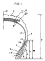
- Fig. 1 is a semi-cross sectional view of a pneumatic radial tire according to an embodiment of the present invention.
- Fig. 2 is a semi-cross sectional view of a pneumatic radial tire according to another embodiment of the present invention.
- Fig. 1 is a semi-cross sectional view illustrating a pneumatic radial tire for a passenger car in a widthwise direction thereof according to a first embodiment of the present invention.
- a tire has a carcass 2, the distal ends of which are folded back axially about a pair of bead cores 1 from the inside of a tire to the outside thereof, a tread portion 3 which is disposed at the crown portion of the carcass 2, a pair of side wall portions 4, a belt layer 5 made of at least two layers disposed inwardly from the tread portion 3 in the radial direction thereof, and a belt reinforcing layer 6 made of at least one layer disposed outwardly from the belt layer 5 at positions corresponding to the entire tread portion 3 and/or the end portions thereof.
- the belt reinforcing layer is formed by spirally winding a rubber-coated and narrow strip made of a single fiber cord or a plurality of fiber cords around a tire such that the fiber cord/cords are provided substantially in parallel to the circumferential direction of the tire.
- a pair of bead fillers 7 are disposed directly above the bead cores 1, respectively.
- the carcass 2 is formed by disposing fiber cords typically made of rayon in a direction substantially orthogonal to the circumferential direction of a tire, and is formed of at least one layer.
- the belt layer 5 is formed by non-elongation cords typically made of aromatic-series polyamide fiber or steel cord, which are disposed to be inclined at the angle 10° to 30° with respect to the circumferential direction of a tire (i.e., the equatorial direction of a tire) in a state in which at least two non-elongation cords overlap one another and intersect with each other in different directions thereof.
- Each of the bead fillers 7 is interposed between the carcass body and a carcass folding portion 8, of the carcass 2.
- a base portion 7Aof the bead filler 7 is tapered from a portion directly above the bead core 1 so as to form a substantially triangular cross section.
- a region 7B of the bead filler 7 has a substantially constant cross sectional width and extends from the upper portion of the base portion 7A to the upper end portion of the bead filler 7.
- the height L from the bottom surface of a bead portion 9 to the upper end portion of the bead filler 7 corresponds to 20 to 60% of the height T from the bead portion bottom surface to the upper end portion of the tread portion 3 (which is referred to as a "tire cross sectional height” hereinafter).
- the height K from the bead portion bottom surface to the upper end portion of the carcass folding portion corresponds to 15 to 40% of the tire cross sectional height T, and is shorter than the bead filler height L.
- the hardness of rubber for a bead filler has 76 to 99 degrees at a type-A durometer hardness, described in JISK6253-1993.
- a bead reinforcing layer 10 is disposed outwardly from the carcass folding portion in the widthwise direction of a tire such that steel cords forming the bead reinforcing layer are inclined at the angle of 10° to 60° with respect to the radial direction of a tire.
- the height M from the bead portion bottom surface to the upper end portion of the bead reinforcing layer 10 (which is referred to as a "bead reinforcing layer height”) corresponds to 20 to 60% of the tire cross sectional height T, and is shorter than the bead filler height L.
- the belt reinforcing layer 6 is shown in Fig. 1 in which the belt reinforcing layer 6 is comprised of a first belt reinforcing layer 11 which is wound around the belt layer 5 at the outer circumferential direction thereof over the portions corresponding to the entire tread portion 3, and a second belt reinforcing layer 12 which is wound around the end portions of the first belt reinforcing layer 11 at the outer circumferential direction thereof.
- the belt reinforcing layer 6 in which the first belt reinforcing layer 11 may be formed by one layer or two layers, and the first belt reinforcing layer 11 may be combined with the second belt reinforcing layer 12 having one layer or two layers can be applied to the present invention.
- the belt reinforcing layer 6 is made of organic fiber cords. It is preferable that the organic fiber cords have a 1.8% or less elongation under load of 1.4 g/den at the temperature of 50 ⁇ 5°C, and have a 2.0 to 3.0% elongation under load of 0.7g/den at the temperature of 170 ⁇ 5°C.
- the belt reinforcing layer 6 is spirally wound around a tire.
- a method in which side portions of a narrow strip are butted, portions of the strip are overlapped one another, or an interval is provided between the strips adjacent to each other can be applied to the present invention.
- Fig. 2 shows another embodiment of the present invention.
- the bead filler 7 is tapered from the bottom surface to the upper end portion of a filler so as to be substantially uniformed. Since other structures are the same as those of the first embodiment, a description therefor will be omitted.
- a tire was experimentally manufactured in which a tire size is 225/60R16 and a rim size is 7JJ.
- a layer of PEN cords was disposed on a cap 11 and a layer 12 of the tire according to the present invention.
- Respective sizes of portions of the bead filler 7 in Fig. 1 is such that the bead filler height is 45mm, the filler bottom surface width is 6mm, and the filler base portion height is 25mm.
- the hardness of rubber for the bead filler is 98 degrees at the hardness of a type-A durometer which is described in JISK6253-1993.
- a layer of the bead reinforcing layer 10 is disposed outwardly from the carcass folding portion in a manner that steel cords are inclined at the angle 22° with respect to the radial direction of the tire.
- structures which are not shown in Table 2 are the same.
- the experimentally manufactured tire is assembled in a rim of a size 7JJ with an internal pressure 2.0 kgf/cm 2 , and is installed at a 4000 cc class of a domestic passenger car, and the vehicle interior noise of the car and the stability and controllability thereof were evaluated.
- Noise level db (A) was metered at the interior of a vehicle at the traveling speed of 60km/h.
- the feeling test was effected by a test driver using test cords and the test includes a zigzag traveling test and a high-speed cornering test in test cords.
- +1 is marked.
- -1 is marked.
- ⁇ 2 is marked.
- cord material PEN nylon alamido denier 1500/2 1260/2 1500/2 elongation (%) under load of 1.4 g/d, 50 ⁇ 5°C 1.3 4.2 1.2 elongation (%) under load of 0.7 g/d, 170 ⁇ 5°C 2.2 4.5 0.8
Claims (11)
- Pneumatischer Reifen mit:wobei zumindest zwei Gürtelschichten (5) einwärts des Laufbereichs (3) angeordnet sind,einem Paar von Wulstbereichen (9) ;einem Paar von Kernreitern (7), welche direkt oberhalb von Wulstkernen (1) dieses Paars von Wulstbereichen (9) angeordnet sind;einer Karkasse (2) mit einer toroidförmigen Ausgestaltung, welche sich über die Wulstbereiche hinüber erstreckt;einem Laufbereich (3), welcher an dem Kronenbereich der Karkasse (2) positioniert ist; undeinem Paar von Seitenwandbereichen (4),
wobei zumindest eine Gürtelverstärkungsschicht (6) auswärts von den Gürtelschichten (5) in radialer Richtung an Stellen vorgesehen ist, welche dem gesamten Bereich und/oder den Endbereichen des Laufbereichs entsprechen,
wobei die Gürtelverstärkungsschicht (6) geformt ist durch spiralförmiges Wickeln eines gummibeschichteten und engen Streifens aus einer einzelnen Faserkorde oder mehreren Faserkorden um einen Reifen herum, so dass die Faserkorden im Wesentlichen parallel zur Umfangsrichtung des Reifens vorgesehen sind, wobei die Gürtelverstärkungsschicht (6) aus organischen Faserkorden besteht,
dadurch gekennzeichnet, dass
die Faserkorde eine Elongation von 2,7% oder weniger unter einer Belastung von 1,4 g/den bei einer Temperatur von 50±5°C hat und eine Elongation von 1,5 bis 6% bei einer Belastung von 0,7 g/den bei einer Temperatur von 170±5°C, und
die Höhe (L) jedes Kernreiters (7) 20 bis 60% der Querschnittshöhe (T) des Reifens entspricht. - Pneumatischer Reifen nach Anspruch 1, wobei jeder Kernreiter (7) zwischen einem Karkassenkörper und einem Karkassenfaltbereich (8) der Karkasse vorgesehen ist, wobei ein Basisbereich (7a) des Kernreiters (7), welcher direkt oberhalb der Wulstkerne (1) vorgesehen ist, sich nach auswärts in radialer Richtung eines Reifens verjüngt, und wobei der Kernreiter (7) sich bei einer im Wesentlichen konstanten Querschnittsbreite vom oberen Endbereich des Basisbereichs (7a) bis zum distalen Endbereich des Kernreiters erstreckt.
- Pneumatischer Reifen nach Anspruch 1 oder 2, wobei eine Wulstverstärkungsschicht (10) bei dem Karkassenfaltbereich (8) nach außen in Richtung der Breite des Reifens angeordnet ist, so dass die Richtung der Korden, welche die Wulstverstärkungsschicht (10) bilden, sich im Winkel von 10 bis 60° bezüglich der radialen Richtung eines Reifens neigt.
- Pneumatischer Reifen nach Anspruch 3, wobei die Höhe (M) der Wulstverstärkungsschicht 20 bis 60% der Reifenquerschnittshöhe entspricht.
- Pneumatischer Reifen nach Anspruch 3 oder 4, wobei die Höhe (M) der Wulstverstärkungsschicht höher ist als die Höhe (L) des Kernreiters.
- Pneumatischer Reifen nach Anspruch 1 bis 5, wobei eine Höhe (K) des Karkassenfaltbereichs 15 bis 40% der Reifenquerschnittshöhe entspricht und niedriger ist als die Höhe (L) des Kernreiters.
- Pneumatischer Reifen nach Anspruch 1 bis 6, wobei die Faserkorde eine Elongation von 1,8% oder weniger unter einer Belastung von 1,4 g/den bei einer Temperatur von 50±5°C hat und eine Elongation unter einer Belastung von 0,7 g/den bei einer Temperatur von 170±5°C.
- Pneumatischer Reifen nach Anspruch 1 bis 7, wobei die organische Faserkorde einen Gradienten N1 der Tangente der Belastungs-Elongations-Kurve hat, angezeigt unter einer Belastung von 1,4 g/den bei einer Temperatur von 50±5°C, und einen Gradienten N2 der Tangente dieser Kurve unter einer Belastung von 0,25 g/den bei der gleichen Temperatur, wobei das Verhältnis von N1 zu N2 0,8 bis 1,3 beträgt.
- Pneumatischer Reifen nach Anspruch 1 bis 8, wobei die Faserkorde ausgeformt ist durch Korden, bei denen 30% oder mehr der Gesamtindikationsanzahl von Denier aus Polyethylen-2,6-Naphthalat-Faser gemacht ist.
- Pneumatischer Reifen nach Anspruch 1 bis 9, wobei die Faserkorde aus Polyethylen-Terephthalat-Faser gemacht ist.
- Pneumatischer Reifen nach Anspruch 1 bis 10, wobei die Gürtelschichtkorde aus Stahlkorden gemacht ist.
Applications Claiming Priority (6)
| Application Number | Priority Date | Filing Date | Title |
|---|---|---|---|
| JP19493796 | 1996-07-24 | ||
| JP194937/96 | 1996-07-24 | ||
| JP19493796 | 1996-07-24 | ||
| JP13547397 | 1997-05-26 | ||
| JP13547397A JP3763931B2 (ja) | 1996-07-24 | 1997-05-26 | 空気入りラジアルタイヤ |
| JP135473/97 | 1997-05-26 |
Publications (3)
| Publication Number | Publication Date |
|---|---|
| EP0820882A2 EP0820882A2 (de) | 1998-01-28 |
| EP0820882A3 EP0820882A3 (de) | 1998-05-13 |
| EP0820882B1 true EP0820882B1 (de) | 2002-10-09 |
Family
ID=26469319
Family Applications (1)
| Application Number | Title | Priority Date | Filing Date |
|---|---|---|---|
| EP97112768A Expired - Lifetime EP0820882B1 (de) | 1996-07-24 | 1997-07-24 | Radialer Luftreifen |
Country Status (5)
| Country | Link |
|---|---|
| US (1) | US6253816B1 (de) |
| EP (1) | EP0820882B1 (de) |
| JP (1) | JP3763931B2 (de) |
| DE (1) | DE69716190T2 (de) |
| ES (1) | ES2181960T3 (de) |
Families Citing this family (14)
| Publication number | Priority date | Publication date | Assignee | Title |
|---|---|---|---|---|
| JP2001163005A (ja) * | 1999-12-09 | 2001-06-19 | Bridgestone Corp | ラジアルタイヤ |
| US6651716B1 (en) * | 2000-02-23 | 2003-11-25 | The Goodyear Tire & Rubber Company | Method and tire adapted for post cure tire uniformity correction |
| JP3453353B2 (ja) * | 2000-11-09 | 2003-10-06 | 住友ゴム工業株式会社 | 空気入りラジアルタイヤ |
| FR2836655B1 (fr) * | 2002-03-04 | 2005-02-11 | Michelin Soc Tech | Armature de sommet avec nappe d'epaule |
| WO2003086782A1 (fr) * | 2002-04-18 | 2003-10-23 | Bridgestone Corporation | Pneumatique |
| JP4044526B2 (ja) * | 2004-01-27 | 2008-02-06 | 住友ゴム工業株式会社 | 空気入りタイヤとリムとの組立体 |
| JP2007045245A (ja) * | 2005-08-08 | 2007-02-22 | Bridgestone Corp | 空気入りラジアルタイヤ |
| JP4478646B2 (ja) | 2005-12-21 | 2010-06-09 | 住友ゴム工業株式会社 | 空気入りタイヤ |
| JP4900016B2 (ja) * | 2007-04-17 | 2012-03-21 | 横浜ゴム株式会社 | 空気入りタイヤ |
| BRPI0722266B1 (pt) * | 2007-11-15 | 2018-10-16 | Pirelli | processo para fabricar um pneu e aparelho para construir uma estrutura de carcaça de um pneu para rodas de veículo |
| JP5486638B2 (ja) * | 2012-05-31 | 2014-05-07 | ピレリ・タイヤ・ソチエタ・ペル・アツィオーニ | 車両ホイール用タイヤを製造するための方法および車両ホイール用タイヤのカーカス構造を構築するための装置 |
| CN108099501A (zh) * | 2017-12-18 | 2018-06-01 | 安徽佳通乘用子午线轮胎有限公司 | 一种提升耐久度的充气轮胎 |
| KR102194785B1 (ko) * | 2019-04-15 | 2020-12-24 | 한국타이어앤테크놀로지 주식회사 | 보강재를 구비한 공기압 타이어 |
| DE102022200360A1 (de) * | 2022-01-14 | 2023-07-20 | Continental Reifen Deutschland Gmbh | Fahrzeugluftreifen |
Citations (1)
| Publication number | Priority date | Publication date | Assignee | Title |
|---|---|---|---|---|
| EP0454432A2 (de) * | 1990-04-26 | 1991-10-30 | Sumitomo Rubber Industries Limited | Radialer Luftreifen |
Family Cites Families (5)
| Publication number | Priority date | Publication date | Assignee | Title |
|---|---|---|---|---|
| JPH04154410A (ja) * | 1990-10-17 | 1992-05-27 | Sumitomo Rubber Ind Ltd | 空気入りラジアルタイヤ |
| JPH05139112A (ja) | 1991-11-15 | 1993-06-08 | Sumitomo Rubber Ind Ltd | 空気入りタイヤ |
| JP3426278B2 (ja) * | 1993-03-09 | 2003-07-14 | 株式会社ブリヂストン | 操縦安定性に優れた空気入りタイヤ |
| US5526863A (en) * | 1994-04-18 | 1996-06-18 | Michelin Recherche Et Technique S.A. | Tire with reduced bead mass |
| JP3555809B2 (ja) | 1995-06-19 | 2004-08-18 | 株式会社ブリヂストン | ラジアルタイヤ |
-
1997
- 1997-05-26 JP JP13547397A patent/JP3763931B2/ja not_active Expired - Fee Related
- 1997-07-23 US US08/899,208 patent/US6253816B1/en not_active Expired - Lifetime
- 1997-07-24 ES ES97112768T patent/ES2181960T3/es not_active Expired - Lifetime
- 1997-07-24 DE DE69716190T patent/DE69716190T2/de not_active Expired - Lifetime
- 1997-07-24 EP EP97112768A patent/EP0820882B1/de not_active Expired - Lifetime
Patent Citations (1)
| Publication number | Priority date | Publication date | Assignee | Title |
|---|---|---|---|---|
| EP0454432A2 (de) * | 1990-04-26 | 1991-10-30 | Sumitomo Rubber Industries Limited | Radialer Luftreifen |
Also Published As
| Publication number | Publication date |
|---|---|
| JPH1086607A (ja) | 1998-04-07 |
| EP0820882A2 (de) | 1998-01-28 |
| ES2181960T3 (es) | 2003-03-01 |
| EP0820882A3 (de) | 1998-05-13 |
| JP3763931B2 (ja) | 2006-04-05 |
| DE69716190T2 (de) | 2003-06-12 |
| DE69716190D1 (de) | 2002-11-14 |
| US6253816B1 (en) | 2001-07-03 |
Similar Documents
| Publication | Publication Date | Title |
|---|---|---|
| EP1867497B1 (de) | Run-flat-reifen | |
| US7036541B2 (en) | Pneumatic tire | |
| KR100551870B1 (ko) | 공기 레이디얼 플라이 타이어 | |
| EP0820882B1 (de) | Radialer Luftreifen | |
| US20050284554A1 (en) | Pneumatic tire | |
| KR20010013460A (ko) | 저가의 경량 레이디얼 타이어 | |
| KR100551869B1 (ko) | 공기 레이디얼 플라이 타이어 | |
| EP0346106A1 (de) | Luftreifen | |
| CN106994865B (zh) | 充气轮胎 | |
| US20090107605A1 (en) | Pneumatic tire and method for producing same | |
| EP0297889A2 (de) | Luftreifen | |
| US5396943A (en) | Pneumatic tires for two-wheeled vehicles | |
| JP2769040B2 (ja) | 高速走行用空気入りラジアルタイヤ | |
| US6305452B1 (en) | Pneumatic radical tire for passenger car with carcass ply cut-out zone | |
| US5238039A (en) | Pneumatic radial tires having carcass line with plural inflection points | |
| KR20180064419A (ko) | 공기 타이어 | |
| EP3960497B1 (de) | Reifen | |
| JP2001121917A (ja) | 空気入りラジアルタイヤ | |
| EP1182060B1 (de) | Luftreifen | |
| JP2702583B2 (ja) | 乗用車用空気入りラジアルタイヤ | |
| JP2001047820A (ja) | 空気入りタイヤ | |
| US20220266636A1 (en) | Pneumatic tire | |
| JP3321458B2 (ja) | 二輪車用空気入りタイヤ | |
| US6298892B1 (en) | Pneumatic tire with specified carcass profile in bead portions | |
| JPH06336102A (ja) | 非対称空気入りタイヤおよびその製造方法 |
Legal Events
| Date | Code | Title | Description |
|---|---|---|---|
| PUAI | Public reference made under article 153(3) epc to a published international application that has entered the european phase |
Free format text: ORIGINAL CODE: 0009012 |
|
| AK | Designated contracting states |
Kind code of ref document: A2 Designated state(s): DE ES FR GB IT |
|
| AX | Request for extension of the european patent |
Free format text: AL;LT;LV;RO;SI |
|
| RTI1 | Title (correction) | ||
| RHK1 | Main classification (correction) |
Ipc: B60C 9/22 |
|
| PUAL | Search report despatched |
Free format text: ORIGINAL CODE: 0009013 |
|
| AK | Designated contracting states |
Kind code of ref document: A3 Designated state(s): AT BE CH DE DK ES FI FR GB GR IE IT LI LU MC NL PT SE |
|
| AX | Request for extension of the european patent |
Free format text: AL;LT;LV;RO;SI |
|
| RHK1 | Main classification (correction) |
Ipc: B60C 15/06 |
|
| 17P | Request for examination filed |
Effective date: 19980619 |
|
| AKX | Designation fees paid |
Free format text: DE ES FR GB IT |
|
| RBV | Designated contracting states (corrected) |
Designated state(s): DE ES FR GB IT |
|
| GRAG | Despatch of communication of intention to grant |
Free format text: ORIGINAL CODE: EPIDOS AGRA |
|
| 17Q | First examination report despatched |
Effective date: 20011031 |
|
| GRAG | Despatch of communication of intention to grant |
Free format text: ORIGINAL CODE: EPIDOS AGRA |
|
| GRAH | Despatch of communication of intention to grant a patent |
Free format text: ORIGINAL CODE: EPIDOS IGRA |
|
| GRAH | Despatch of communication of intention to grant a patent |
Free format text: ORIGINAL CODE: EPIDOS IGRA |
|
| GRAA | (expected) grant |
Free format text: ORIGINAL CODE: 0009210 |
|
| AK | Designated contracting states |
Kind code of ref document: B1 Designated state(s): DE ES FR GB IT |
|
| REG | Reference to a national code |
Ref country code: GB Ref legal event code: FG4D |
|
| REF | Corresponds to: |
Ref document number: 69716190 Country of ref document: DE Date of ref document: 20021114 |
|
| REG | Reference to a national code |
Ref country code: ES Ref legal event code: FG2A Ref document number: 2181960 Country of ref document: ES Kind code of ref document: T3 |
|
| ET | Fr: translation filed | ||
| PLBE | No opposition filed within time limit |
Free format text: ORIGINAL CODE: 0009261 |
|
| STAA | Information on the status of an ep patent application or granted ep patent |
Free format text: STATUS: NO OPPOSITION FILED WITHIN TIME LIMIT |
|
| 26N | No opposition filed |
Effective date: 20030710 |
|
| REG | Reference to a national code |
Ref country code: DE Ref legal event code: R082 Ref document number: 69716190 Country of ref document: DE Representative=s name: HOFFMANN - EITLE, DE |
|
| REG | Reference to a national code |
Ref country code: FR Ref legal event code: CA Effective date: 20140812 |
|
| REG | Reference to a national code |
Ref country code: DE Ref legal event code: R082 Ref document number: 69716190 Country of ref document: DE Representative=s name: HOFFMANN - EITLE PATENT- UND RECHTSANWAELTE PA, DE Effective date: 20140828 Ref country code: DE Ref legal event code: R082 Ref document number: 69716190 Country of ref document: DE Representative=s name: HOFFMANN - EITLE, DE Effective date: 20140828 Ref country code: DE Ref legal event code: R081 Ref document number: 69716190 Country of ref document: DE Owner name: BRIDGESTONE CORPORATION, JP Free format text: FORMER OWNER: BRIDGESTONE CORP., TOKIO/TOKYO, JP Effective date: 20140828 |
|
| PGFP | Annual fee paid to national office [announced via postgrant information from national office to epo] |
Ref country code: GB Payment date: 20140721 Year of fee payment: 18 Ref country code: ES Payment date: 20140728 Year of fee payment: 18 |
|
| PGFP | Annual fee paid to national office [announced via postgrant information from national office to epo] |
Ref country code: IT Payment date: 20140729 Year of fee payment: 18 |
|
| GBPC | Gb: european patent ceased through non-payment of renewal fee |
Effective date: 20150724 |
|
| PG25 | Lapsed in a contracting state [announced via postgrant information from national office to epo] |
Ref country code: IT Free format text: LAPSE BECAUSE OF NON-PAYMENT OF DUE FEES Effective date: 20150724 Ref country code: GB Free format text: LAPSE BECAUSE OF NON-PAYMENT OF DUE FEES Effective date: 20150724 |
|
| REG | Reference to a national code |
Ref country code: FR Ref legal event code: PLFP Year of fee payment: 20 |
|
| REG | Reference to a national code |
Ref country code: ES Ref legal event code: FD2A Effective date: 20160826 |
|
| PGFP | Annual fee paid to national office [announced via postgrant information from national office to epo] |
Ref country code: DE Payment date: 20160722 Year of fee payment: 20 |
|
| PG25 | Lapsed in a contracting state [announced via postgrant information from national office to epo] |
Ref country code: ES Free format text: LAPSE BECAUSE OF NON-PAYMENT OF DUE FEES Effective date: 20150725 |
|
| PGFP | Annual fee paid to national office [announced via postgrant information from national office to epo] |
Ref country code: FR Payment date: 20160721 Year of fee payment: 20 |
|
| REG | Reference to a national code |
Ref country code: DE Ref legal event code: R071 Ref document number: 69716190 Country of ref document: DE |