EP0820549B1 - Vorrichtung zum verdichten von erdreich und zum setzen eines ankers - Google Patents
Vorrichtung zum verdichten von erdreich und zum setzen eines ankers Download PDFInfo
- Publication number
- EP0820549B1 EP0820549B1 EP96912681A EP96912681A EP0820549B1 EP 0820549 B1 EP0820549 B1 EP 0820549B1 EP 96912681 A EP96912681 A EP 96912681A EP 96912681 A EP96912681 A EP 96912681A EP 0820549 B1 EP0820549 B1 EP 0820549B1
- Authority
- EP
- European Patent Office
- Prior art keywords
- soil
- foundation
- plate
- rod
- anchoring
- Prior art date
- Legal status (The legal status is an assumption and is not a legal conclusion. Google has not performed a legal analysis and makes no representation as to the accuracy of the status listed.)
- Expired - Lifetime
Links
- 239000002689 soil Substances 0.000 claims abstract description 103
- 238000004873 anchoring Methods 0.000 claims abstract description 45
- 238000007596 consolidation process Methods 0.000 claims abstract description 30
- 238000009434 installation Methods 0.000 abstract description 15
- 238000012360 testing method Methods 0.000 abstract description 7
- 238000000034 method Methods 0.000 abstract description 6
- POIUWJQBRNEFGX-XAMSXPGMSA-N cathelicidin Chemical compound C([C@@H](C(=O)N[C@@H](CCCNC(N)=N)C(=O)N[C@@H](CCCCN)C(=O)N[C@@H](CO)C(=O)N[C@@H](CCCCN)C(=O)N[C@@H](CCC(O)=O)C(=O)N[C@@H](CCCCN)C(=O)N[C@@H]([C@@H](C)CC)C(=O)NCC(=O)N[C@@H](CCCCN)C(=O)N[C@@H](CCC(O)=O)C(=O)N[C@@H](CC=1C=CC=CC=1)C(=O)N[C@@H](CCCCN)C(=O)N[C@@H](CCCNC(N)=N)C(=O)N[C@@H]([C@@H](C)CC)C(=O)N[C@@H](C(C)C)C(=O)N[C@@H](CCC(N)=O)C(=O)N[C@@H](CCCNC(N)=N)C(=O)N[C@@H]([C@@H](C)CC)C(=O)N[C@@H](CCCCN)C(=O)N[C@@H](CC(O)=O)C(=O)N[C@@H](CC=1C=CC=CC=1)C(=O)N[C@@H](CC(C)C)C(=O)N[C@@H](CCCNC(N)=N)C(=O)N[C@@H](CC(N)=O)C(=O)N[C@@H](CC(C)C)C(=O)N[C@@H](C(C)C)C(=O)N1[C@@H](CCC1)C(=O)N[C@@H](CCCNC(N)=N)C(=O)N[C@@H]([C@@H](C)O)C(=O)N[C@@H](CCC(O)=O)C(=O)N[C@@H](CO)C(O)=O)NC(=O)[C@H](CC=1C=CC=CC=1)NC(=O)[C@H](CC(O)=O)NC(=O)CNC(=O)[C@H](CC(C)C)NC(=O)[C@@H](N)CC(C)C)C1=CC=CC=C1 POIUWJQBRNEFGX-XAMSXPGMSA-N 0.000 description 16
- 239000012530 fluid Substances 0.000 description 11
- 230000000452 restraining effect Effects 0.000 description 9
- 238000005452 bending Methods 0.000 description 7
- 238000005056 compaction Methods 0.000 description 6
- 239000004033 plastic Substances 0.000 description 6
- 239000004567 concrete Substances 0.000 description 3
- 239000002184 metal Substances 0.000 description 3
- 229910052751 metal Inorganic materials 0.000 description 3
- 239000000853 adhesive Substances 0.000 description 2
- 230000001070 adhesive effect Effects 0.000 description 2
- 230000002265 prevention Effects 0.000 description 2
- 239000011435 rock Substances 0.000 description 2
- 229910001018 Cast iron Inorganic materials 0.000 description 1
- 239000004593 Epoxy Substances 0.000 description 1
- BQCADISMDOOEFD-UHFFFAOYSA-N Silver Chemical compound [Ag] BQCADISMDOOEFD-UHFFFAOYSA-N 0.000 description 1
- 229910000831 Steel Inorganic materials 0.000 description 1
- 229910000746 Structural steel Inorganic materials 0.000 description 1
- 230000004913 activation Effects 0.000 description 1
- 239000011248 coating agent Substances 0.000 description 1
- 238000000576 coating method Methods 0.000 description 1
- 230000006835 compression Effects 0.000 description 1
- 238000007906 compression Methods 0.000 description 1
- 230000001010 compromised effect Effects 0.000 description 1
- 230000002596 correlated effect Effects 0.000 description 1
- 230000000875 corresponding effect Effects 0.000 description 1
- 230000008878 coupling Effects 0.000 description 1
- 238000010168 coupling process Methods 0.000 description 1
- 238000005859 coupling reaction Methods 0.000 description 1
- 230000000694 effects Effects 0.000 description 1
- 230000008030 elimination Effects 0.000 description 1
- 238000003379 elimination reaction Methods 0.000 description 1
- 238000011900 installation process Methods 0.000 description 1
- 239000000463 material Substances 0.000 description 1
- 229910052709 silver Inorganic materials 0.000 description 1
- 239000004332 silver Substances 0.000 description 1
- 239000007787 solid Substances 0.000 description 1
- 239000010959 steel Substances 0.000 description 1
- 238000005728 strengthening Methods 0.000 description 1
Images






Classifications
-
- E—FIXED CONSTRUCTIONS
- E02—HYDRAULIC ENGINEERING; FOUNDATIONS; SOIL SHIFTING
- E02D—FOUNDATIONS; EXCAVATIONS; EMBANKMENTS; UNDERGROUND OR UNDERWATER STRUCTURES
- E02D7/00—Methods or apparatus for placing sheet pile bulkheads, piles, mouldpipes, or other moulds
- E02D7/20—Placing by pressure or pulling power
-
- E—FIXED CONSTRUCTIONS
- E02—HYDRAULIC ENGINEERING; FOUNDATIONS; SOIL SHIFTING
- E02D—FOUNDATIONS; EXCAVATIONS; EMBANKMENTS; UNDERGROUND OR UNDERWATER STRUCTURES
- E02D27/00—Foundations as substructures
- E02D27/10—Deep foundations
- E02D27/12—Pile foundations
-
- E—FIXED CONSTRUCTIONS
- E02—HYDRAULIC ENGINEERING; FOUNDATIONS; SOIL SHIFTING
- E02D—FOUNDATIONS; EXCAVATIONS; EMBANKMENTS; UNDERGROUND OR UNDERWATER STRUCTURES
- E02D27/00—Foundations as substructures
- E02D27/32—Foundations for special purposes
- E02D27/50—Anchored foundations
-
- E—FIXED CONSTRUCTIONS
- E02—HYDRAULIC ENGINEERING; FOUNDATIONS; SOIL SHIFTING
- E02D—FOUNDATIONS; EXCAVATIONS; EMBANKMENTS; UNDERGROUND OR UNDERWATER STRUCTURES
- E02D5/00—Bulkheads, piles, or other structural elements specially adapted to foundation engineering
- E02D5/74—Means for anchoring structural elements or bulkheads
- E02D5/80—Ground anchors
-
- E—FIXED CONSTRUCTIONS
- E02—HYDRAULIC ENGINEERING; FOUNDATIONS; SOIL SHIFTING
- E02D—FOUNDATIONS; EXCAVATIONS; EMBANKMENTS; UNDERGROUND OR UNDERWATER STRUCTURES
- E02D7/00—Methods or apparatus for placing sheet pile bulkheads, piles, mouldpipes, or other moulds
Definitions
- This invention relates to methods, devices and systems for utilizing and/or increasing the load bearing capacity of soil, and more particularly, to an anchoring and foundation apparatus adapted to be installed in a hole in the earth.
- Structural foundations are designed to transmit the weight of the structure to the underlying soil or rock, and serve as a basic supporting member.
- the foundation must be essentially unyielding, since one of the chief requirements is the minimization or elimination of settlement due to yielding of the soil under the applied loads.
- Structural foundations are of two main types, namely, spread foundations and pilings.
- a spread foundation is a structural element designed to distribute a concentrated load to reduce the distributed pressure to an allowable level which can safely be supported by the soil thereunder.
- Bearing piers or caissons are used for this purpose.
- Such piers can be friction piles, which are supported through skin friction in a manner well known in the art.
- bearing pier foundations provide very little, if any, resistance to twisting loads applied to the foundation, since their primary purpose is to support vertical loads.
- Spread foundations are preferable because they are relatively inexpensive compared to piles.
- the safe bearing capacity or bearing value of the soil is less than the pressure applied to the soil by the foundation, then the foundation must be made of piles, unless the soil can be stabilized.
- the most popular way to stabilize the soil is through compaction by vibrating devices or rollers.
- U.S. Patent 4,843,785 shows an anchoring and foundation support apparatus which includes consolidation and shear plates pivotally mounted at the end of a rod.
- a spreader assembly is carried by the rod and acts on the plates to move then outwardly.
- an anchoring and foundation apparatus adapted to be installed in a hole in the earth including a support rod disposed within a tube, said rod including threads and a threaded nut being threadably received on said rod to cooperate with a stop surface, a pivot plate secured to said tube, said pivot plate including a plurality of pivot pins secured thereto, a plurality of spaced media consolidation plates, each of said media consolidation plates including a media facing surface having an upper edge, a lower edge, said upper edge positioned relatively closer to said pivot plate than said lower edge, and a lug, each of said lugs being pivotally attached to said pivot plate through respective ones of said pivot pins, a rib disposed along at least said lower edge of respective ones of said media consolidation plates, an engagement member secured to said rod adjacent said media consolidation plates and adapted to contact said media consolidation plates and to force said media consolidation plates outwardly and upwardly when moved in an upward direction, said engagement member having a tapered contacting surface, an actuator for moving said rod and said engagement member upwardly
- the anchoring and foundation apparatus has a bearing and moment foundation for use in soil having an upper surface, a lower surface and a converging side surface.
- the upper surface is adapted to receive a pushing force for pushing the foundation into the soil.
- the side surface is adapted to contact the soil when a pushing force is applied to the upper surface.
- the converging side surface converges from the upper surface to the lower surface and defines at least one cutting edge.
- the cutting edge is a tip defined by the side surface.
- the bearing plate is secured to the vertical support and adapted to rest on a soil surface, whereby the bearing plate is forced into the soil and in turn compacts and consolidates the soil when the consolidation plates are forced outwardly into the soil to compact and consolidate the soil adjacent thereto.
- the anchoring and foundation apparatus can be used to install a pier foundation having a plug, an installation load bearing member, an installed load bearing member and a cap.
- the plug extends along a first longitudinal axis and includes a first section and a second section. The first section is adapted to receive a pushing force and the second section is adapted to rest on the soil.
- the installation load bearing member extends along the first longitudinal axis and includes a first end and a second end. The first end of the installation load bearing member is received by the first section of the plug.
- the installed load bearing member extends along a second longitudinal axis and includes a first end and a second end. The first end of the installed load bearing member is received by the first section of the plug.
- the cap coacts with the second end of the load bearing member.
- the cap is adapted to receive a pushing force, whereby the pushing force applied to the cap causes a pushing force to be applied to the installation load bearing member, which causes a pushing force to be applied to the first section of the plug.
- the cap, plug, installed load bearing member and/or the installation load bearing member can be combined to form a kit.
- a waterproof sleeve such as a plastic sleeve, can be secured to an outer surface of a wooden installed member.
- An extendable hydraulic setting tool and an anchor can be used to install the foundation.
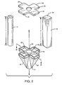
- FIGS. 1-3 of the drawings show a pier foundation 10 for use in soil, made in accordance with the present invention.
- FIG. 1 shows the pier foundation 10 being installed into soil 11.
- the pier foundation includes a plug 12 extending along a vertical or longitudinal axis, a hollow cylindrical bearing member or installation load member 14, four wooden piers or installed load members 16 (of which only one is shown in FIG. 2), and a cap 18.
- the plug 12 which is also shown in FIGS. 1-3 and 10, can be a unitary body made of concrete, plastic or metal, such as cast iron, and includes an upper section defining four recessed compartments 20 equally spaced around a central hole. A central tubular section extends downwardly from the central hole and is coaxial therewith.
- Four soil engaging sections or legs 22 are provided on a lower section of the plug 12 with each lower section having an angled surface that converge toward a lower end of the tube from an adjacent compartment 20 forming a tip.
- the outer perimeter of the lower end of the tube is less than the outer perimeter of an upper end of the lower section.
- the upper end of the lower section of the plug 12 is adjacent the upper section of the plug 12.
- Soil engaging sections 22 have a triangular shaped cross-section.
- the plug 12 is adapted to receive a lower end of the hollow cylinder 14 so that the lower end of the hollow cylinder 14 abuts against the plug 12 on a surface 23 to pass compressive forces thereto.
- the hollow cylinder 14 is coaxial with the plug central tubular section.
- the compartments 20 include a square recess that receives the wooden piers 16, which have a square cross-section.
- the recesses and piers 16 can also take any other shape.
- the hollow cylinder member 14 has a longer length L than the length L' of the piers 16.
- Piers 16 extend along axes parallel to the X axis which also pass through respective soil engaging sections 22.
- piers 16 are positioned adjacent sections 22.
- the cap 18 looks similar to the upper section of the plug 12 and includes four recessed compartments equally spaced around a central hole. Upper ends of the wooden piers 16 are received within recesses defined by the compartments 24. An upper end of hollow cylindrical member 14 abuts against a lower surface 26 of the cap 18. Preferably, a gap 28 is present between the cap surface 26 and the upper ends 29 of wooden piers 16. Piers 16 can also be made of plastic, metal or concrete.
- a bore hole 30 is dug in uncompacted soil.
- the bore hole preferably has the same or a slightly larger diameter than the inner diameter of the lower end of the plug tubular section.
- an anchor 40 is set in the soil by an anchoring device 50, such as that disclosed in United States Patent No. 4,967,997, which is hereby incorporated by reference, or such as anchoring devices which are described hereinafter.
- the anchoring device 50 includes a threaded rod or vertical support 52 and a hydraulic actuating arrangement 53 positioned directly above the plug 12, which includes two spaced apart hydraulic motor mean 54 each having a piston movable within a cylinder and a piston arm. Movement of the piston causes the piston arm to extend or retract.
- the motor means are secured to a bearing plate 56, so that the piston arms pass through spaced holes in the bearing plate 56.
- a retaining nut is threadedly received by the rod 52 and abuts against an upper surface of the bearing plate 56 to prevent upward vertical movement of the bearing plate 56.
- the hydraulic cylinders are fluidly coupled to hoses so that the cylinder can be charged with hydraulic fluid to cause the piston arms to extend outwardly from their respective cylinders.
- a change of hydraulic fluid pressure on the cylinder changes the distance between the upper surface of cap 18 and plate 56.
- the hoses are connected to a pressure gauge G and hydraulic fluid is contained within the hose and cylinders.
- a hole is provided in the plate 56 through which the threaded rod 52 passes.
- a tube or column 58 passes through hollow cylindrical members 24.
- a lower end of the threaded rod 52 attaches to an anchor pivot plate assembly 60 that includes side plates adapted to engage with a portion of the bore hole wall 30. Tube 58 is secured to the pivot plate assembly 60. Pivot plate assembly 60 and rod 52 form an anchor.
- the anchoring device 50 is first installed in the soil without the pier foundation 10, so as to cause the side plates to engage the soil as shown in FIG. 1 and in a manner known in the art and described, for example in United States Patent No. 4,974,997, which is hereby incorporated by reference.
- the anchor can be installed by an anchoring device described hereinafter.
- any other anchor can be placed in the soil.
- the hydraulic actuating arrangement 53 is removed and then the plug 12 is placed on the surface of the soil over the hole 30 and the tube 58 so that the plug central tubular section is coaxial with the bore hole 30.
- the tube 58 has a diameter less than the inner diameters of the plug tube and the hollow cylindrical member 14.
- Piers 16 are received by compartments 20 and the cap 18 is placed over the piers 16 and rests on the hollow cylindrical member 14.
- the hole defined in cap 18 is coaxial with the longitudinal axis.
- a threaded coupling and threaded rod may be required to extend the rod 52 above plate 56.
- the hydraulic actuating arrangement 53 is then reconnected to rod 52 so that the piston arms of the motor means 54 rest on the cap 18.
- the restraining nut is then replaced to abut against an upper surface of plate 56.
- the hydraulic motor means 54 are then actuated by pressurizing the hydraulic fluid. This causes the piston arms to bear against or coact with the cap 18 and force the plug and at least a portion of hollow cylindrical member 14 and piers 16 into the soil.
- the hydraulic motor means 54 apply a pushing force to the cap 18.
- the majority of the compressive forces pass from the cap 18 to the plug 12 through the hollow cylinder 14 since the upper ends 30 of the wooden piers 16 are initially spaced from the bases of the compartments 24.
- some compressive forces are passed to the wooden piers 16 due to the soil friction forces f applied to the sides of the wooden piers 16 as the pier foundation 10 is forced into the soil. In that case, the wooden piers 16 may be slightly lifted from the plug 12 so that the upper ends 29 of the wooden piers 16 contact the cap 18.
- the soil below the cap 18 and the plug 12 is then compacted and consolidated.
- the hydraulic motor means 54 is activated until a proper reading is obtained on the pressure gauge G to indicate the extent of compaction and consolidation of the soil around and below the foundation. Preferably, the reading is taken while the plug 12 is forced into the soil.
- the hydraulic motor means may have to be deactivated so that the piston arms retract, the bearing plate lowered and the restraining nut lowered several times during the process. The piston can then be reactivated further pushing the plug into the soil. This is due to the limited length of the piston arm.
- the motor means 54 can be activated until the wooden piers are set to a fixed depth in the soil.
- the bearing plate 56, the motor means 54, the cap 18 and the hollow cylindrical member 14 are removed.
- the rod and the anchor pivot plate assembly can be removed by lowering the rod 52 so as to cause the plates to retract and be raised upwardly and removed. In some instances, it may be preferable to leave the anchor in place if a structure is to be attached to rod 52, requiring uplift prevention.
- a structure compressive force F can now be supported on the wooden piers 16, as shown in FIG. 4. Since the majority of the installation compressive force is taken up by the hollow cylindrical member 14, the wooden piers 16 have a greater integrity than had they taken the initially compressive forces due to installing the plug 12.
- the cap 18 can then be replaced onto the wooden piers 16 so as to rest on upper ends 29 of the wooden piers 16 or a bearing plate 56 can be secured to the upper ends 29 of the wooden piers 16 so that a structure can be supported thereon.
- a central wooden pier (not shown) 16 can also be placed over the plug central hole and rest on the plug 12 to give added support in conjunction with the existing wooden piers 16.
- FIGS. 7-9 show several top views of various plug arrangements 12', 12'', and 12''', having central holes and recessed compartments 20', 20'' and 20''' to receive wooden piers 16.
- FIG. 11 shows a top perspective view of plug 12''. Corresponding top caps are also required, although not shown.
- the piers 16 can be provided with plastic sleeves 64, as shown in FIG. 12.
- other waterproof materials can be used for the sleeves 64 in lieu of plastic.
- the sleeves are tightly received or bonded to the wooden piers 16 by an adhesive, such as epoxy or a waterproof adhesive so that moisture does not accumulate between the sleeve 64 and the wooden pier 16.
- a waterproof coating can be applied to the piers 16.
- FIG. 13 shows an alternate installation device where the motor means 54 is replaced with a hydraulically activated hollow core cylinder arrangement 68, such as the single-acting hollow plunger or piston and hydraulic cylinder manufactured and sold by Enerpac of Butler, Wisconsin under the trademark Holl-o-Cylinder®.
- a hydraulically activated hollow core cylinder arrangement 68 such as the single-acting hollow plunger or piston and hydraulic cylinder manufactured and sold by Enerpac of Butler, Wisconsin under the trademark Holl-o-Cylinder®.
- Such hollow core cylinders are well known in the art and have annular holes defined in both the cylinder and the piston.
- Threaded rod 52 passes through the hollow core or annular holes defined in the piston 70 and of the cylinder arrangement 68.
- the restraining nut is received by rod 52 and rests on an upper surface of the piston 70 of the cylinder arrangement 68.
- a lower portion of the cylinder arrangement 68 rests on an upper surface of the cap 18.
- the cylinder arrangement 68 is connected to a hydraulic pump and pressure gauge via hoses. Supplying pressurized hydraulic fluid to the cylinder arrangement 68 causes the hollow plunger to extend upwardly and forces the pier foundation 10 downwardly. Individual elements of the plug 12, hollow cylinder 14, piers 16 and cap 18 can be sold as a kit.
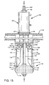
- Anchoring device 100 is shown in FIGS. 14-16 and can be used to set the pier foundation 10.
- Anchoring device 100 is similar to anchoring device 50, except for the below noted differences.
- Anchoring device 100 includes a threaded longitudinal rod or vertical support 102 that extends along the longitudinal axis X through a tube 104.
- a single-acting, hollow plunger cylinder 103 such as an Enerpac Holl-O-Cylinder® Single-Acting Hollow Plunger Hydraulic Cylinders manufactured by Enerpac, 13000 W. Silver Spring Drive, Butler, Wisconsin 53007, is coupled to an upper end of the rod 102.
- the single-acting, hollow plunger cylinder 103 includes a cylinder having an extendable hollow plunger or piston slideably received therein.
- the plunger When pressurized hydraulic fluid is supplied to the cylinder 103, the plunger extends in an upwardly direction along the longitudinal X axis.
- the upper end of the rod 102 passes through the plunger and a restraining nut 105 is threadably received by the rod 102 and rests on an upper surface of the plunger.
- a lower end of the cylinder 103 rests on a bearing plate 106.
- An upper end of tube 104 abuts a lower surface of the bearing plate 106.
- Tube 104 includes an annular plate 107 provided at an upper end thereof and through which rod 102 passes.
- a lower end of the threaded rod 102 is coupled to an anchor pivot plate assembly 110 that includes bottom side plates or media consolidation plates 112 which are pivotally or swingably attached to a pivot plate or top cap 114 by pins 113 at pivot points.
- bottom side plates or media consolidation plates 112 which are pivotally or swingably attached to a pivot plate or top cap 114 by pins 113 at pivot points.
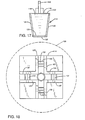
- four side plates 112 are provided spaced 90 degrees apart (only two plates are shown spaced 180 degrees apart). However, two side plates 112 spaced 180 degrees apart or any other number of equally spaced plates 112 will suffice.
- a lower end of tube 104 is secured to an upper surface of the pivot plate 114 and rod 102 passes through pivot plate 114.
- a pivot plate engagement member or cone 116 is attached to a lower end of the rod 102 by two nuts threadedly received thereon.
- Cone 116 includes an angled or tapered upper surface that is adapted to force the bottom side plates 112 outwardly when it and rod 102 are moved in
- each side plate 112 includes a substantially flat plate 118 having a soil engagement surface or media facing surface 119 with soil cutting bars or ribs 120 and 122 extending outwardly therefrom.
- Each of the soil engagement surfaces 119 includes an upper edge 123 and a lower edge 124, where the upper edge is positioned closer than the pivot plate 114 than the lower edge 124. It is believed that most preferably the cutting bar 122 be present while cutting bars 120 are optional. A cutting bar should not be positioned along the upper edge 123 of the soil engagement surface.
- Angled cutting bars 120 extend along opposite side edges of soil engagement surface 119 and bar 122 extends along the lower edge 124 of soil engagement surface 119, which is furthest from the pivot plate 114.
- Each plate 118 is attached to a lug 126 which is positioned at an angle ⁇ with respect to the soil engagement surface 119 of plate 118 so that oppositely positioned soil engagement surfaces 119 converge toward cone 116 when the outer edges of side bars 120 extend vertically and parallel to the longitudinal axis in an initial position prior to engagement with the soil.
- angle ⁇ is such that the entire soil engagement surface 119 of each plate 118 initially contacts the bore hole walls during engagement, as opposed to only a portion of the soil engagement surfaces 119 initially contacting the wall, such as will happen if ⁇ is zero degrees.
- Lugs 126 are pivotally secured by pivot pins to downwardly extending support brackets 127 of pivot plate 114. As shown in FIG.
- pivot plate 114 is less than the inner diameter of the bore hole 30. Also, when the plates 112 are in an initial nonengaged position, the side bars 120 and 122 will not contact the bore hole wall. Hence, the pivot plate assembly 110 can easily pass through the hole 30 and be guided by the outer edges of bars 120 and 122.
- each upper end 128 of lug 126 is in the shape of a circular arc and is received by load bearing socket or support member 130.
- each socket 130 has two legs preferably spaced 90 degrees apart, and can be made of angle iron.
- Each socket defines a sliding surface 131 which slideably contacts the upper end 128 of lug 126.
- the sockets 130 are secured to support brackets 127 of the pivot plate 114 and add support to the lugs 126 as the side plate 112 engages with the soil, thereby preventing undue stresses to the pivot pins 113 that secure the lugs 126 to the pivot plate 114.
- a bore hole 30 is formed, i.e., by boring, in uncompacted and unconsolidated soil 11.
- the cone 116 is secured to a lower end of rod 102 and the pivot plate assembly 110 and tube 104 are received by the rod 102.
- the tube 104, pivot plate assembly 110, cone 116 and the lower end of rod 102 are lowered into the bore hole 30.
- the bearing plate 106 is placed on an upper surface of the soil 11 so as to rest on an upper surface of the tube 104.
- the hollow plunger cylinder 103 is placed over an upper end of the rod 102 and is secured to the plate 106 by the restraining nut 105, which is threadably received by the upper end of the rod 102 and as shown in FIG.
- Cylinder 103 is then fluidly coupled to a pump P and gauge G. Pressurized hydraulic fluid is supplied to the cylinder 103 through a hose H by the pump P causing the plunger to move upwardly.
- a valve V is provided to direct the flow of hydraulic fluid from the pump P to the cylinder 103 in a manner well known in the art.
- Bearing plate 106 is urged downwardly and cone 116 is urged upwardly by rod 102 causing side plates 112 to pivot upwardly toward bearing plate 106.
- bars 122 engage the bore hole surface, the soil positioned adjacent to and between the bearing plate 106 and the soil engaging surfaces 119 is consolidated and compacted. This continues until the anchoring device 100 is set in the soil and/or the desired amount of compaction and consolidation is achieved, as shown in FIG. 16.
- the anchoring device 100 can then be removed and a structure placed on the compacted and consolidated soil. Alternatively, the anchor can be left in the soil and a structure attached to rod 102 where bearing and uplift prevention is required.
- the zones of influence defined between bearing plate 106 and plate 118 is greater than if the plate 106 were absent during the installation of anchor 100. Further, it is believed that by using the bearing plate 106 in combination with plates 118 only one rib, rib 122, is required on the plates 118, as opposed to two ribs, such as disclosed in United States Patent Nos. 4,882,891 or 4,843,785, which are hereby incorporated by reference.
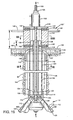
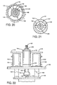
- FIGS. 19-21 of the drawings show another embodiment of an anchoring device 100' made in accordance with the present invention.
- Anchoring device 100' is similar to anchoring device 100, except for the following differences.
- Like numerals are used for like elements.
- a nut 132 is threadably received by the rod 102 positioned above the pivot plate assembly 110. Tightening of the nut 132 locks the side plates 112 in place as will be discussed hereinafter.
- a nut socket 134 matingly engages the nut 132.
- a tubular sleeve 136 is secured to nut socket 134.
- Rod 102 passes through nut socket 134 and sleeve 136.
- An upper end of the sleeve 136 includes a plurality of radially extending fins or drive members 138 received by slots defined in a nut tightening apparatus 140.
- the nut tightening apparatus 140 includes a central cylindrical member 141 having a central bore with elongated slots defined therein. Rod 102 passes through the central bore. Thrust bearings 142 are provided on upper and lower ends of the cylindrical member 141. End plates 143 and 144 are secured to thrust bearings 142. Coaxial holes are provided in the end plates 143 and 144 to permit rod 102 to pass therethrough.
- the hole in plate 143 has a diameter sufficient to permit fins 138 to pass therethrough.
- the hole in plate 144 has a diameter sufficient to permit rod 102 to pass therethrough.
- the hole diameter in plate 143 is larger than the hole diameter in plate 144.
- Tubular sleeve 136 passes through plate 143.
- the slots defined in cylindrical member 141 permit fins 138 to move vertically along the X axis relative to the cylindrical member 141.
- the slots prevent fins 138 to rotate about the longitudinal X axis relative to the cylindrical member 141.
- Thrust bearings 142 permit the cylindrical member 141 to be rotated even when the nut tightening apparatus is under compression by cylinder 103 and bearing plate 106 as the side plates 112 are being engaged into the soil.
- nut 132 will loosen and travel upwardly toward bearing plate 106 and permit disengagement of the side plates 112 from the soil.
- Removable handles 145 are provided on cylindrical member 141 to permit a person to rotate the central cylindrical member 141 relative to the end plates 143 and 144.
- handles 145 are rods threadably received by threaded bores in the central cylindrical member 141.
- the length of L'' fins 138 should be substantially less than the length L''' of longitudinal slot in cylindrical member 141 so that there can be substantial freedom of movement in the longitudinal direction of the tube 130 during tightening and loosening of the nut 132. It is preferable that the fins 138 be positioned adjacent end plate 144 during tightening nut 132 and adjacent plate 143 during loosening nut 132.
- the anchoring device 100' is inserted into a bore hole in the same manner as anchoring device 100.
- the socket 134 and sleeve 136 are received on rod 102 and engage nut 132.
- Nut 132 is sufficiently positioned on rod 102 so as not to contact pivot plate 114 when the side plates 112 are engaged in the soil.
- Nut tightening apparatus 140 is then placed on bearing plate 106 and the cylinder 103 is placed on the plate 144 of nut tightening apparatus 140.
- the nut 132 is tightened after the bottom side plates 112 are engaged in the bore hole wall.
- cylinder 103, bearing plate 106, socket 134, the sleeve 136 and nut tightening apparatus 140 are removed and a structure and/or foundation can be secured to rod 102 and be anchored in place.
- FIG. 19 of the drawings also shows that strengthening and guiding fins 146 can be secured to tube 104. Fins 146 add rigidity to tube 104 and assist guiding tube 104 in the bore hole 30. Also, a lower end of tube 104 can be threaded to pivot plate 114. A centering collar 148 can also be provided through which the tube 104 passes. Collar 148 includes a central tube that is received at an upper end of bore hole 30 and an annular flange attached to the central tube. The flange rests on an upper surface of the soil 11 adjacent bore hole 30. Wooden beams 149 can be provided and are sandwiched between plate 106 and the soil 11.
- nut 132 can be positioned on the rod 102 above the bearing plate 106.
- the bearing plate has a hole sufficient to permit rod 102 to pass therethrough, but small enough to permit nut 132 to abut against an upper surface thereof.
- a support plate 160 is provided.
- Two spaced apart hydraulic cylinder arrangements 162 are provided.
- Each arrangement 162 includes a cylinder 164 having extendable pistons 166.
- One such hydraulic cylinder arrangement is a double-acting solid plunger hydraulic cylinder manufactured and sold by Enerpac. Pressurized hydraulic fluid causes the pistons to extend outwardly.
- the cylinders 164 are attached to the support plate 160 and the respective pistons pass through holes defined in the support plate 160.
- the nut socket 134 and sleeve 136 are similar to that shown in FIG. 19, except the sleeve 136 is shorter than that shown in FIG. 19.
- the nut tightening apparatus 140 is positioned over a hole defined in the support plate 160 through which the upper portion of sleeve 136 and rod 102 pass.
- a restraining nut 105 is secured on an upper end of the rod 102 and abuts against an upper surface of plate 144.
- nut tightening apparatus 140 includes modifying socket 134 so that it extends the entire length of the tubular sleeve 136 or extends a sufficient length to permit the nut 132 to travel a distance in the longitudinal X direction within the socket 134.
- the sleeve is substantially shortened.
- An end of the shortened socket or sleeve can have fins 138 received in the slots of cylindrical member 141 in the same manner as previously discussed or the upper end of the socket or the tubular sleeve can be fixedly secured to the cylindrical member 141.
- the thrust bearings and end plates of nut tightening apparatus 140 remain the same.
- the nut moves within the socket along the longitudinal X axis during engagement of the plates 112.
- the socket then is rotated thereby tightening the nut 132 against the pivot plate 114.
- the process is reversed to loosen the nut 132.
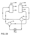
- FIG. 23 shows a schematic drawing of the hydraulic circuit supplying pressurized hydraulic fluid to cylinders 164.
- Pistons 166 extend away from cylinders 164 when manifold M 1 is directly fluidly coupled to a hydraulic pump and manifold M 2 is directly fluidly coupled to the pump reservoir. Pistons 166 retract when M 1 is directly fluidly coupled to the reservoir and M 1 is directly coupled to the pump. The flow can be reversed by adjusting a valve V so as to cause the pistons 166 to retract. Such an arrangement is well known in the art.
- Support plate 160 and the cylinder arrangement 162 shown in FIGS. 22 and 23 can be used to replace the cylinder 103.
- Anchoring devices 100 and 100' can be used in lieu of anchoring device 50 to install the pier foundation 10.
- the structure to be supported by the foundation is subjected not only to compressive forces and tensile forces, but also bending moments.
- One such example is a billboard, which can have both torsional moment and bending moment applied thereto due to wind effects.
- a mandrel type or bearing and moment foundation 170 may be used as shown in FIGS. 24-27.
- the mandrel type foundation 170 includes a rectangular shaped upper bearing plate 172 having a central hole and a tube 174, which is coaxial with the hole, attached to the bearing plate 172 and depending from an underside of the bearing plate 172.
- Angled side members 176 having side surfaces converge from an underside of the plate 172 to a circular distal end of the tube 174 and define a lower surface of the foundation and has a tip or cutting edge 178.
- Angled side members 176 define a wedge member. The distal end portion of the tube 174 forms part of tip 178.
- Tip 178 also includes straight portions extending 180 degrees apart extending from the circular portion of the tube 174.
- the base of the wedge member adjacent the bearing plate 172 is rectangular shaped.
- a horizontally extending lip portion 179 extends beyond the base section of side members 176.
- the foundation 170 may be made of plastic, wood, metal or concrete.
- the bottom side plates 112 are set in the soil as previously discussed.
- the upper portion of the anchoring device i.e., the cylinders and bearing plate 106, are removed and the rod 102 is passed through the tube 174.
- the inner diameter of tube 174 is greater than tube 104.
- Tubes 104 and 174 are positioned so that they are coaxial with each other and tip 178 rests on the upper surface of soil 11.
- Bearing plate 106 and cylinders are then coupled to rod 102 so that the bearing plate 106 rests on an upper surface of bearing plate 172.
- Bearing plate 106 is now spaced apart from an upper portion of tube 104. Activation of the hydraulic cylinder pushes or forces the mandrel type foundation 170 into the soil.
- the converging side surfaces of the angled side members 176 contact, compact and consolidate the surrounding soils outwardly and downwardly in a predetermined manner and ratio. This is continued until the lip 179 contacts the soil 11 and further compacts and consolidates the soil. The lip 179 prevents slippage of the soil and aids in further compaction.
- the dimensions A and B of the side members 176 differ about the Y and Z axes. This affects the torsional strength of the foundation about the longitudinal X axis as well as the bending strength about the Y and Z axes.
- mandrel foundation 170 utilizes frictional forces between the side members 176 and the soil, and the outward and downward compaction and consolidation of a prestressed zone of the soil, which results in a strong foundation that can resist the above-described twisting and overturning or bending moment, plus provide load bearing strength.
- the strength of the foundation to resist the bending moments about the Y and Z axes is a function of the angles ⁇ and ⁇ , respectively.
- ⁇ and ⁇ are defined between the respective angled side members 176 and an axis parallel to the X axis.
- the greater the surface area about the perimeter of side members 176 the greater the load bearing capacity of the foundation 170 due to the frictional forces.
- ⁇ and ⁇ should be greater than zero degrees. It is believed that the larger the value of angles ⁇ and ⁇ , the more the foundation 170 will resist bearing.
- one of the angles ⁇ and ⁇ could be zero degrees while the other of the angles ⁇ and ⁇ would be greater than zero degrees, so that only two oppositely positioned side members 176 converge toward each other and the other two oppositely positioned side members 176 are parallel to each other.
- the lip 179 is contained in a plane normal to the X axis.
- a foundation 170 can be custom designed (i.e., the angles ⁇ and ⁇ can be determined as well as the dimensions A and B and the length L'''' of the foundation 170) once the load bearing, bending moment and twisting moment characteristics of the structure to be supported are known.
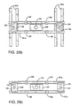
- FIGS. 28a-32 A solution to this problem is the use of a grillage 180 as shown in FIGS. 28a-32.
- the grillage 180 includes a plurality of structural members 181a and 181b, such as timbers or steel I-beams, that are criss-crossed.
- a plurality of auxiliary anchors 182 are installed to hold the two pairs of auxiliary structural members 181b in place. Any type of anchor can be used.
- each auxiliary anchor 182 is coupled to a bearing plate 106, which is supported on the auxiliary structural members 181b.
- a center anchor 184 is then installed between a pair of intermediate structure members 181a utilizing an anchoring device, such as anchoring device 100 or 100' as previously discussed.
- the auxiliary structural members 181b rest on intermediate structural members 181a.
- the intermediate structural members 181a rest on the auxiliary structural members 181b.
- no auxiliary structural members 181b are present and the intermediate structural members 181a rest on the ground having anchors 182 and bearing plates 106 positioned at the ends thereof.
- a foundation 185 can be installed by placing the foundation 185 on the soil 11 between the pair of intermediate structural members 181 (of which only one is shown) of the grillage shown in FIG. 28b, placing the centering collar 148 on an upper surface of the foundation 185 so that the central collar tube rests on an upper surface of the foundation 185.
- Hydraulic cylinder 103 rests on an upper surface of the centering collar flange.
- a bearing plate 106 rests on top of the piston of hydraulic cylinder 103. Bearing plate 106 is spaced away from tube 104.
- anchor removal member 186 rests on an upper surface of bearing plate 106 and is secured to anchor 184.
- anchor removal member 186 includes a hollow tubular member 188 attached to an upper base plate 190 and a lower base plate 191.
- a plurality of fins 192 attach to base plates 190 and 191 and hollow tubular member 188.
- a plurality of holes are formed in the base plate 190 adapted to receive cables or threaded rods 194.
- four rods 194 pass through the respective holes adjacent respective corners of plate 190 and are secured at distal ends to respective brackets 196 attached to grillage intermediate structural members 181 of the grillage 180 shown in FIG. 28b.
- Restraining nuts 198 are secured to ends of cables 194 and rest on plate 190.
- Central holes are provided in base plates 190 and 191, which are coaxial with the hollow tubular member 188, thereby defining a passageway.
- pressurizing the hydraulic cylinder 103 causes the hydraulic cylinder piston to extend bearing against bearing plate 106.
- the bearing plate 106 bears or is forced against the anchor removal member 186, which is held in place by the rods 194 connected to the grillage 180.
- the cylinder 103 forces the foundation 185 into the soil 11.
- the grillage 180 as shown in FIG. 28b, the centering column 148, the cylinder 103 and the anchor removal member 186 can be removed and a structure can be placed on the installed foundation 185.
- the grillage 180 can remain and be used to support a structure, such as a trailer home in combination with one of the foundations 185 and/or anchorages 182 and 184.
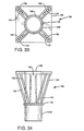
- the centering column 148 should be of sufficient length so that an upper portion of tube 104 does not contact the cylinder 103 during installation of the foundation 185. Further, as shown in FIG. 29, support vanes 200 can be secured to the outer surface of a tubular member 202 forming a friction type foundation 185.
- FIG. 30 shows an arrangement for installing a friction type foundation 185, which is similar as shown in FIG. 29, except cylinder 103 is replaced by cylinder arrangements 162 and the tightening apparatus 140 is provided and positioned between anchor removal member 186 and support plate 160, and the grillage 180 is of the type shown in FIG. 28c.
- the centering column 148 should be of sufficient length so that an upper portion of tube 104 does not contact bearing plate 106 during setting of the foundation.
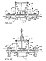
- FIG. 31 shows an arrangement to test the strength of the foundation after it has been installed using the grillage 180 shown in FIG. 28b.
- the restraining nut 105 is removed (the anchor 184 can also be removed).
- Cylinders 162 are pressurized to a predetermined pressure to cause the piston arms 166 to bear against the top of the foundation 185. If the foundation 185 does not move in the downwardly direction, then it is properly installed.
- this arrangement can be used to test the strength of auxiliary anchors 182. In that case, a foundation need not be set in the soil.
- a bearing plate can be laid on top of the soil in lieu of the foundation in the arrangement shown in FIG. 31. Expansion of the pistons will cause a test pulling force applied to the auxiliary anchors 182 through the anchor removal member 186, rods 194 and structural members 181a and 181b. If the anchors do not move, then they have been properly installed.
- the hydraulic setting device 100 can be removed by loosening nut 132 using the nut tightening apparatus 140 so that the bottom side plates can be positioned into a retracted vertical position.
- a lifting truck T can then be connected to the fins 146.
- the anchoring device 184 is then raised through the bore hole 30 and the passageway of the anchor removal member 186 and centering collar 148.
- any number of structural members 181a and 181b can be used to form a grillage as described, so that the grillage can be expanded along the soil surface to accommodate many different types of geometries and more than one foundation. Further, any of the grillages disclosed can be substituted for one another, can be used to install any of the foundations disclosed herein, and can be utilized on any of the anchors disclosed.
Landscapes
- Engineering & Computer Science (AREA)
- Structural Engineering (AREA)
- Life Sciences & Earth Sciences (AREA)
- General Life Sciences & Earth Sciences (AREA)
- Mining & Mineral Resources (AREA)
- Paleontology (AREA)
- Civil Engineering (AREA)
- General Engineering & Computer Science (AREA)
- Piles And Underground Anchors (AREA)
- Foundations (AREA)
- Soil Working Implements (AREA)
- Dowels (AREA)
- Investigating Strength Of Materials By Application Of Mechanical Stress (AREA)
Claims (8)
- Verankerungs- und Fundamentvorrichtung zur Installation in einem Erdloch mit einer in einer Röhre (104) angeordneten Stützstange (102), wobei die genannte Stange (102) Gewinde und eine Gewindemutter (105) aufweist, die auf die genannte Stange (102) aufgeschraubt werden kann, so dass sie mit einer Anschlagoberfläche zusammenwirkt, mit einer Drehplatte (114), die an der genannten Röhre (104) angebracht ist, wobei die genannte Drehplatte eine Mehrzahl von daran befestigten Drehzapfen (113) aufweist, mit einer Mehrzahl beabstandeter Medien-Verdichtungsplatten (112), wobei jede der genannten Medien-Verdichtungsplatten (112)) eine zu den Medien ausgerichtete Oberfläche (119) mit einer Oberkante (123), einer Unterkante (124) aufweist, wobei die genannte Oberkante (123) im Verhältnis dichter an der genannten Drehplatte (114) positioniert ist als die genannte Unterkante (124), und mit einem Ansatz (126), wobei jeder der genannten Ansätze (126) drehbar an der genannten Drehplatte (114) über entsprechende der genannten Drehzapfen (113) angebracht ist, mit einer Rippe (122), die mindestens entlang der genannten Unterkante (124) der entsprechenden genannten Medien-Verdichtungsplatten (112) angeordnet ist, mit einem Eingriffselement (1166), das angrenzend an die genannten Medien-Verdichtungsplatten (112) an der genannten Stange angebracht und in der Lage ist, die genannten Medien-Verdichtungsplatten (112) zu berühren und die genannten Medien-Verdichtungsplatten (112) auswärts und aufwärts zu drücken, wenn eine Bewegung nach oben erfolgt, wobei das genannte Eingriffselement (116) eine konische Berührungsoberfläche aufweist, mit einem Betätigungselement (103) zum Bewegen der genannten Stange (102) und des genannten Eingriffselements (116) nach oben, so dass die genannten Medien-Verdichtungsplatten (112) auswärts und aufwärts geschwenkt werden, dadurch gekennzeichnet, dass die Drehplatte (114) eine Mehrzahl von Stützelementen (130) aufweist, wobei jedes der genannten Elemente eine Stützoberfläche (131) aufweist, und wobei jeder der genannten Ansätze (126) ein bogenförmiges oberes Ende (128) aufweist, wobei die genannten gebogenen Enden (128) verschiebbar aufgenommen werden und verschiebbar eine entsprechende der genannten Stützoberflächen (131) verschiebbar berühren, und dass eine integrale Lagerplatte (106) oberhalb der genannten Drehplatte angeordnet ist, so dass sie auf einem Erdboden ruht, wobei die genannte Lagerplatte (106) in den genannten Erdboden gedrängt wird und die genannte Erde zwischen der genannten Lagerplatte (106) und den genannten Medien-Verdichtungsplatten (112) zusammendrückt und verdichtet, wenn die genannten Medien-Verdichtungsplatten (112) nach oben und außen in die Erde in Richtung der genannten Lagerplatte gedrückt werden.
- Verankerungs- und Fundamentvorrichtung nach Anspruch 1, dadurch gekennzeichnet, dass es sich bei dem Eingriffselement um einen Konus (116) handelt.
- Verankerungs- und Fundamentvorrichtung nach Anspruch 1 oder 2, dadurch gekennzeichnet, dass die Rippen (120) entlang der Seiten der entsprechenden Medien-Verdichtungsplatten (112) angeordnet sind.
- Verankerungs- und Fundamentvorrichtung nach Anspruch 3, dadurch gekennzeichnet, dass die Rippen (120) konisch sind.
- Verankerungs- und Fundamentvorrichtung nach einem der Ansprüche 1 bis 4, dadurch gekennzeichnet, dass Führungs- und Stützelemente (146) an der Röhre (104) vorgesehen sind.
- Verankerungs- und Fundamentvorrichtung nach Anspruch 5, dadurch gekennzeichnet, dass es sich bei den Führungs- und Stützelementen (146) um Finnen handelt, die um eine äußere Oberfläche der Röhre (104) angeordnet sind.
- Verankerungs- und Fundamentvorrichtung nach einem der vorstehenden Ansprüche, dadurch gekennzeichnet, dass es sich bei dem Betätigungselement (103) um einen Hohlkernzylinder handelt.
- Verankerungs- und Fundamentvorrichtung nach Anspruch 1, dadurch gekennzeichnet, dass nur eine Rippe (122) vorgesehen und entlang ausschließlich der Unterkante (124) jeder Medien-Verdichtungsplatte (112) angeordnet ist.
Applications Claiming Priority (3)
| Application Number | Priority Date | Filing Date | Title |
|---|---|---|---|
| US08/420,430 US5622015A (en) | 1995-04-12 | 1995-04-12 | Method and apparatus for consolidating earth and anchor setting device |
| US420430 | 1995-04-12 | ||
| PCT/US1996/004991 WO1996032543A1 (en) | 1995-04-12 | 1996-04-11 | Method and apparatus for consolidating earth and anchor setting device |
Publications (3)
| Publication Number | Publication Date |
|---|---|
| EP0820549A1 EP0820549A1 (de) | 1998-01-28 |
| EP0820549A4 EP0820549A4 (de) | 1998-10-07 |
| EP0820549B1 true EP0820549B1 (de) | 2001-08-01 |
Family
ID=23666442
Family Applications (1)
| Application Number | Title | Priority Date | Filing Date |
|---|---|---|---|
| EP96912681A Expired - Lifetime EP0820549B1 (de) | 1995-04-12 | 1996-04-11 | Vorrichtung zum verdichten von erdreich und zum setzen eines ankers |
Country Status (7)
| Country | Link |
|---|---|
| US (2) | US5622015A (de) |
| EP (1) | EP0820549B1 (de) |
| AT (1) | ATE203789T1 (de) |
| AU (1) | AU696435B2 (de) |
| CA (1) | CA2217961A1 (de) |
| DE (1) | DE69614256D1 (de) |
| WO (1) | WO1996032543A1 (de) |
Families Citing this family (26)
| Publication number | Priority date | Publication date | Assignee | Title |
|---|---|---|---|---|
| US6572240B2 (en) * | 1996-07-26 | 2003-06-03 | Gary L. Reinert, Sr. | Stainless steel airport light cannister apparatus and method |
| US7988316B2 (en) | 1998-07-10 | 2011-08-02 | Mfpf, Inc. | Stainless steel airport light cannister apparatus and method |
| US6216803B1 (en) | 1999-06-23 | 2001-04-17 | The Charles Machine Works, Inc. | Anchor assembly |
| JP4699638B2 (ja) * | 2001-06-11 | 2011-06-15 | 株式会社地盤試験所 | 回収型メカニカルアンカー |
| US7621098B2 (en) * | 2001-11-20 | 2009-11-24 | Mfpf, Inc. | Segmented foundation installation apparatus and method |
| GB2384510B (en) * | 2002-01-23 | 2005-06-22 | Cementation Found Skanska Ltd | Construction and design of foundation elements |
| AU2003257232A1 (en) * | 2002-08-26 | 2004-03-11 | James Hardie International Finance B.V. | Soil test box |
| US20040159055A1 (en) * | 2003-02-19 | 2004-08-19 | Stone Ronald L. | Stabilizer for in-ground members, assemblies including the same, and method of installation |
| US7708502B2 (en) * | 2003-11-17 | 2010-05-04 | Joseph D. Carte | System and method for stabilizing landslides and steep slopes |
| US20050232707A1 (en) * | 2004-03-05 | 2005-10-20 | Reinert Gary L Sr | Metal fin pipe foundation apparatus and method |
| US20080185565A1 (en) * | 2007-02-06 | 2008-08-07 | C.E. Shepherd Co., Inc. | Fence and installation method therefor |
| KR100749012B1 (ko) | 2007-04-30 | 2007-08-13 | (주)서림건설 | 쐐기식 선단정착 앵커세트 |
| GR1006289B (el) * | 2008-02-14 | 2009-02-25 | Ιωαννης Λυμπερης | Ελκυστηρας δομικων εργων |
| US20090285637A1 (en) * | 2008-05-16 | 2009-11-19 | W.T.W. Construction, Inc. | Pile mandrel with extendable reaming members |
| US8777520B2 (en) * | 2008-12-08 | 2014-07-15 | Maclean Fogg Company | Piling apparatus |
| KR101076775B1 (ko) | 2009-11-13 | 2011-10-26 | 이민호 | 압축형 그라운드 앵커의 제작 장치 |
| US8920077B2 (en) * | 2011-08-22 | 2014-12-30 | Darin Kruse | Post tensioned foundations, apparatus and associated methods |
| US9062431B2 (en) * | 2012-12-20 | 2015-06-23 | Ulf KOEHLER | Device and method for soil compaction and/or soil stabilization |
| IT201700046356A1 (it) * | 2017-04-28 | 2018-10-28 | Prometec S R L | Testata di ancoraggio per un tirante di ancoraggio |
| US11066827B2 (en) | 2018-03-15 | 2021-07-20 | Daysh Developments, Inc. | Precision dry-stack masonry unit |
| WO2020035803A1 (en) | 2018-08-14 | 2020-02-20 | Lamprell Energy Ltd. | Grillage for use as a foundation for a wind motor |
| US11124938B2 (en) * | 2018-09-04 | 2021-09-21 | Ojjo, Inc. | Expanding foundation components and related systems and methods |
| WO2022034351A1 (en) * | 2020-08-14 | 2022-02-17 | Genima Innovations Marketing Gmbh | Ground anchor |
| CN113293695B (zh) * | 2021-06-08 | 2022-07-19 | 中铁北京工程局集团有限公司 | 基于摩擦减隔震支座的建筑隔震施工方法 |
| US11408137B1 (en) * | 2021-09-14 | 2022-08-09 | Andrew M. Skarphol | Bollard anchor system |
| CN117513301B (zh) * | 2024-01-04 | 2024-04-05 | 北京建筑大学 | 一种用于软土地基处理的复合锚杆结构 |
Family Cites Families (78)
| Publication number | Priority date | Publication date | Assignee | Title |
|---|---|---|---|---|
| US3118284A (en) * | 1964-01-21 | Expansible pile driving mandrel | ||
| NL75044C (de) * | 1900-01-01 | |||
| BE498717A (de) * | ||||
| US676968A (en) * | 1900-10-25 | 1901-06-25 | Alexander A Stanton | Hitching-post. |
| US756374A (en) * | 1903-12-21 | 1904-04-05 | Albert Benroth | Land-anchor. |
| US787017A (en) * | 1904-09-20 | 1905-04-11 | Nat Anchor Company | Anchor. |
| US817044A (en) * | 1905-08-29 | 1906-04-03 | William E Cissna | Land-anchor. |
| US899274A (en) * | 1908-05-12 | 1908-09-22 | Howell M Thomas | Guy-anchor. |
| US948532A (en) * | 1909-01-27 | 1910-02-08 | Clark I Stocking | Post-brace anchor. |
| US963791A (en) * | 1910-01-22 | 1910-07-12 | Frank B Miller | Earth-anchor. |
| US978505A (en) * | 1910-04-23 | 1910-12-13 | William R Stewart | Metallic fence-post. |
| US1173806A (en) * | 1915-06-04 | 1916-02-29 | Nathan C Johnson | Collapsible mandrel particularly adapted for making, forming, and placing concrete piling. |
| US1214679A (en) * | 1915-10-23 | 1917-02-06 | American Steel & Wire Co | Anchor for fence-posts. |
| US1217128A (en) * | 1916-03-10 | 1917-02-20 | Lazarus White | Method of providing substructures for structures. |
| US1330233A (en) * | 1918-11-29 | 1920-02-10 | Blackburn Jasper | Expanding screw-anchor |
| US1598407A (en) * | 1923-12-20 | 1926-08-31 | Edward Ogden J | Ground anchor |
| US1569857A (en) * | 1924-08-05 | 1926-01-19 | American Steel & Wire Co | Fencepost driver |
| US1658155A (en) * | 1926-11-22 | 1928-02-07 | Blackburn Jasper | Earth anchor |
| US1973995A (en) * | 1930-03-21 | 1934-09-18 | Chester R Pieper | Guy anchor |
| US1807488A (en) * | 1930-11-04 | 1931-05-26 | Michalicek Fred | Anchoring device |
| US1948856A (en) * | 1932-05-05 | 1934-02-27 | Walter A Heinrich | Tool for setting earth anchors |
| US1994520A (en) * | 1933-02-06 | 1935-03-19 | Smithjohns Inc | Guy anchor |
| US2176566A (en) * | 1937-08-11 | 1939-10-17 | W C Dillon & Company Inc | Anchor |
| US2187318A (en) * | 1938-11-23 | 1940-01-16 | Gerald G Greulich | Concrete bearing pile |
| US2362556A (en) * | 1942-11-07 | 1944-11-14 | Chance Co Ab | Earth anchor |
| US2490465A (en) * | 1946-05-17 | 1949-12-06 | Harley R Ogburn | Earth anchor |
| US2607198A (en) * | 1948-05-25 | 1952-08-19 | Standard Oil Dev Co | Foundation for use with soft surface formation |
| US2678540A (en) * | 1950-03-11 | 1954-05-18 | Lorenz Hans | Process for the production and sinking of caissons of any desired shape |
| US2779240A (en) * | 1953-05-06 | 1957-01-29 | James W Gaydos | Reflective marker |
| US2942426A (en) * | 1954-06-04 | 1960-06-28 | Ulrich W Stoll | Split-end bearing pile |
| US2933899A (en) * | 1954-08-17 | 1960-04-26 | Walter H Cobi | Pile-driving mandrel |
| US2874547A (en) * | 1956-04-18 | 1959-02-24 | Fiore | Pile driving point and ram for open end pipe piles and h-beam bearing piles |
| US2955430A (en) * | 1958-03-24 | 1960-10-11 | Alston William | Anchor |
| US3011598A (en) * | 1958-04-21 | 1961-12-05 | William H Galloway | Supporting post |
| US2958404A (en) * | 1958-04-25 | 1960-11-01 | John J Smith | Aircraft anchor |
| US2982103A (en) * | 1959-01-12 | 1961-05-02 | Caisson Corp | Method and apparatus for underpinning a building |
| US3056477A (en) * | 1960-05-09 | 1962-10-02 | Francis C Wooley | Hydraulic anchor expander |
| US3066769A (en) * | 1960-05-17 | 1962-12-04 | David B Pasquale | Ground socket |
| US3131544A (en) * | 1961-11-24 | 1964-05-05 | Western Foundation Corp | Driving mandrel |
| NL293220A (de) * | 1962-05-25 | |||
| US3214918A (en) * | 1962-08-15 | 1965-11-02 | Whitney Nat Bank Of New Orlean | Mandrel for pile casings |
| US3187858A (en) * | 1962-12-11 | 1965-06-08 | Atlantic Res Corp | Anchoring device |
| US3222842A (en) * | 1963-01-15 | 1965-12-14 | Harvey Aluminum Inc | Method for installing cemented anchors |
| US3279136A (en) * | 1963-06-27 | 1966-10-18 | Jasper E Smith | Umbrella pile anchor |
| US3342444A (en) * | 1965-07-12 | 1967-09-19 | Allen W Key | Post stabilizer |
| DE1280160B (de) * | 1965-12-09 | 1968-10-10 | Starkstromanlagen Gemeinschaft | Injektionsrammpfahl |
| US3432977A (en) * | 1967-03-08 | 1969-03-18 | Us Navy | Application of shaped charge to earth anchor |
| US3512319A (en) * | 1968-06-07 | 1970-05-19 | All American Eng Co | Earth anchor |
| US3570258A (en) * | 1968-11-25 | 1971-03-16 | Raymond Int Inc | Method and apparatus for vibrating concrete columns |
| US3680274A (en) * | 1970-06-25 | 1972-08-01 | William H Chamberlain | Anchoring device |
| US3763610A (en) * | 1971-05-20 | 1973-10-09 | J Ballew | Earth anchor and apparatus for applying |
| US3797260A (en) * | 1972-05-18 | 1974-03-19 | B Webb | Pipeline anchoring system |
| US4015433A (en) * | 1974-12-30 | 1977-04-05 | Mituo Shibata | Method for settling anchoring device in the ground |
| US3969853A (en) * | 1975-02-03 | 1976-07-20 | Foresight Industries | Torque fin anchor |
| US4023314A (en) * | 1975-10-02 | 1977-05-17 | Tanner Donald L | Mobile home anchor and a method for embedding same |
| US4199277A (en) * | 1976-11-26 | 1980-04-22 | Stanley Merjan | Piling |
| US4083191A (en) * | 1977-01-14 | 1978-04-11 | Donnelly Emmett F | Pier for foundation leveling |
| US4189879A (en) * | 1977-12-05 | 1980-02-26 | Patterson Merle W | Earth anchor |
| US4225269A (en) * | 1978-02-15 | 1980-09-30 | Atsushi Matsui | Funnel-shaped structural block and assemblies of such blocks for shore protection |
| FR2422793A1 (fr) * | 1978-04-10 | 1979-11-09 | Moraly Paul | Cheville destinee a la fixation dans le sol de poteaux ou piquets et dispositif servant a l'enfoncement de cette cheville |
| US4160613A (en) * | 1978-06-23 | 1979-07-10 | Tad Stanwick | Pile anchor for moorings |
| US4351136A (en) * | 1980-01-14 | 1982-09-28 | Raymond International Builders, Inc. | Ground anchor installation |
| FR2519045A1 (fr) * | 1981-12-28 | 1983-07-01 | Rostand Guy | Procede de fondation pour travaux de batiment, de genie civil ou analogues et appareil pour la mise en oeuvre du procede |
| US4547106A (en) * | 1983-03-15 | 1985-10-15 | Yitshaq Lipsker | Ground anchors |
| US4593500A (en) * | 1983-08-01 | 1986-06-10 | Morrow Manufacturing Co., Inc. | Earth anchor with load plate |
| US4530190A (en) * | 1983-12-21 | 1985-07-23 | Goodman Jack P | Self-anchoring fence post and method of installing same |
| US4603520A (en) * | 1985-01-22 | 1986-08-05 | Construction Robotics, Inc. | Post mounting anchor base |
| US4592178A (en) * | 1985-04-09 | 1986-06-03 | Lu Hsi H | Ground anchor |
| US4974997A (en) * | 1986-06-26 | 1990-12-04 | Secure Anchoring & Foundation Equipment, Inc. | Hydraulic setting tool for installing anchoring and foundation support apparatus |
| US4882891A (en) * | 1986-06-26 | 1989-11-28 | S.A.F.E. | Anchoring and foundation support apparatus having moment resisting vanes and method |
| US4843785A (en) * | 1986-06-26 | 1989-07-04 | Secure Anchoring & Foundation Equipment, Inc. | Anchoring and foundation support apparatus and method |
| US4721418A (en) * | 1986-12-15 | 1988-01-26 | Queen Frankie A R | Friction barrier pile jacket |
| US4773793A (en) * | 1987-04-29 | 1988-09-27 | The United States Of America As Represented By The Secretary Of The Navy | Pile having double cone anchor |
| DE3835296A1 (de) * | 1988-10-17 | 1989-03-02 | Bayer Lorenz Dipl Ing Fh | Erdduebel |
| GB8904169D0 (en) * | 1989-02-23 | 1989-04-05 | Alsop Peter | Ground anchoring systems |
| US5108068A (en) * | 1989-08-30 | 1992-04-28 | Gingras Marc M | Support system for free standing poles or posts |
| US5234290A (en) * | 1991-11-04 | 1993-08-10 | Rodney B. Stewart | Prestressed caisson bearing pier and structural foundation device |
| US5460231A (en) * | 1994-08-19 | 1995-10-24 | Collins; James S. | Device and method for augering a conical hole in solid media |
-
1995
- 1995-04-12 US US08/420,430 patent/US5622015A/en not_active Expired - Fee Related
-
1996
- 1996-04-11 AU AU55410/96A patent/AU696435B2/en not_active Ceased
- 1996-04-11 WO PCT/US1996/004991 patent/WO1996032543A1/en not_active Ceased
- 1996-04-11 AT AT96912681T patent/ATE203789T1/de active
- 1996-04-11 EP EP96912681A patent/EP0820549B1/de not_active Expired - Lifetime
- 1996-04-11 CA CA002217961A patent/CA2217961A1/en not_active Abandoned
- 1996-04-11 DE DE69614256T patent/DE69614256D1/de not_active Expired - Lifetime
-
1997
- 1997-04-21 US US08/840,496 patent/US5797704A/en not_active Expired - Lifetime
Also Published As
| Publication number | Publication date |
|---|---|
| WO1996032543A1 (en) | 1996-10-17 |
| US5622015A (en) | 1997-04-22 |
| DE69614256D1 (de) | 2001-09-06 |
| CA2217961A1 (en) | 1996-10-17 |
| EP0820549A4 (de) | 1998-10-07 |
| AU696435B2 (en) | 1998-09-10 |
| US5797704A (en) | 1998-08-25 |
| EP0820549A1 (de) | 1998-01-28 |
| AU5541096A (en) | 1996-10-30 |
| ATE203789T1 (de) | 2001-08-15 |
Similar Documents
| Publication | Publication Date | Title |
|---|---|---|
| EP0820549B1 (de) | Vorrichtung zum verdichten von erdreich und zum setzen eines ankers | |
| EP0648296B1 (de) | Vorgespannter gründungspfahl und fundament | |
| US6193442B1 (en) | Method and device for raising and supporting a building foundation | |
| US6539685B2 (en) | Apparatus and method for lifting sunken foundations | |
| US4974997A (en) | Hydraulic setting tool for installing anchoring and foundation support apparatus | |
| US7416367B2 (en) | Lateral force resistance device | |
| US6352390B1 (en) | Apparatus for lifting and supporting a foundation under tension and compression | |
| US4882891A (en) | Anchoring and foundation support apparatus having moment resisting vanes and method | |
| US7621098B2 (en) | Segmented foundation installation apparatus and method | |
| US5482407A (en) | Helical outrigger assembly serving as an anchor for an underpinning drive assembly | |
| US6872031B2 (en) | Apparatus and method of supporting a structure with a pier | |
| US6848864B1 (en) | Interlocking slab leveling system | |
| US8272810B2 (en) | Pilings for foundation underpinning | |
| US7044686B2 (en) | Apparatus and method for supporting a structure with a pier | |
| US5505561A (en) | Self-piloting compressible piling | |
| US6684577B2 (en) | Support system for lifting and leveling existing buildings that utilizes non-cylindrical support sections and a vertically-adjustable cap that enables the building to be easily raised or lowered to a desired height | |
| US20100080658A1 (en) | System for supporting slab with concrete pier | |
| US4907916A (en) | Pressure grouted pier and pier inserting tool | |
| AU688099B2 (en) | Device and method for augering a conical hole in solid media | |
| CN116676968A (zh) | 一种具备缓冲作用的phc管桩静压设备及其施工方法 | |
| NO20230576A1 (de) | ||
| US20030014929A1 (en) | Piling |
Legal Events
| Date | Code | Title | Description |
|---|---|---|---|
| PUAI | Public reference made under article 153(3) epc to a published international application that has entered the european phase |
Free format text: ORIGINAL CODE: 0009012 |
|
| 17P | Request for examination filed |
Effective date: 19971110 |
|
| AK | Designated contracting states |
Kind code of ref document: A1 Designated state(s): AT BE CH DE DK ES FI FR GB GR IE IT LI NL PT SE |
|
| A4 | Supplementary search report drawn up and despatched |
Effective date: 19980819 |
|
| AK | Designated contracting states |
Kind code of ref document: A4 Designated state(s): AT BE CH DE DK ES FI FR GB GR IE IT LI NL PT SE |
|
| 17Q | First examination report despatched |
Effective date: 19990928 |
|
| GRAG | Despatch of communication of intention to grant |
Free format text: ORIGINAL CODE: EPIDOS AGRA |
|
| RTI1 | Title (correction) |
Free format text: APPARATUS FOR CONSOLIDATING EARTH AND INSTALLING A GROUND ANCHOR |
|
| GRAG | Despatch of communication of intention to grant |
Free format text: ORIGINAL CODE: EPIDOS AGRA |
|
| GRAH | Despatch of communication of intention to grant a patent |
Free format text: ORIGINAL CODE: EPIDOS IGRA |
|
| GRAH | Despatch of communication of intention to grant a patent |
Free format text: ORIGINAL CODE: EPIDOS IGRA |
|
| GRAA | (expected) grant |
Free format text: ORIGINAL CODE: 0009210 |
|
| AK | Designated contracting states |
Kind code of ref document: B1 Designated state(s): AT BE CH DE DK ES FI FR GB GR IE IT LI NL PT SE |
|
| PG25 | Lapsed in a contracting state [announced via postgrant information from national office to epo] |
Ref country code: NL Free format text: LAPSE BECAUSE OF FAILURE TO SUBMIT A TRANSLATION OF THE DESCRIPTION OR TO PAY THE FEE WITHIN THE PRESCRIBED TIME-LIMIT Effective date: 20010801 Ref country code: LI Free format text: LAPSE BECAUSE OF FAILURE TO SUBMIT A TRANSLATION OF THE DESCRIPTION OR TO PAY THE FEE WITHIN THE PRESCRIBED TIME-LIMIT Effective date: 20010801 Ref country code: IT Free format text: LAPSE BECAUSE OF FAILURE TO SUBMIT A TRANSLATION OF THE DESCRIPTION OR TO PAY THE FEE WITHIN THE PRE;WARNING: LAPSES OF ITALIAN PATENTS WITH EFFECTIVE DATE BEFORE 2007 MAY HAVE OCCURRED AT ANY TIME BEFORE 2007. THE CORRECT EFFECTIVE DATE MAY BE DIFFERENT FROM THE ONE RECORDED.SCRIBED TIME-LIMIT Effective date: 20010801 Ref country code: FR Free format text: LAPSE BECAUSE OF FAILURE TO SUBMIT A TRANSLATION OF THE DESCRIPTION OR TO PAY THE FEE WITHIN THE PRESCRIBED TIME-LIMIT Effective date: 20010801 Ref country code: FI Free format text: LAPSE BECAUSE OF FAILURE TO SUBMIT A TRANSLATION OF THE DESCRIPTION OR TO PAY THE FEE WITHIN THE PRESCRIBED TIME-LIMIT Effective date: 20010801 Ref country code: CH Free format text: LAPSE BECAUSE OF FAILURE TO SUBMIT A TRANSLATION OF THE DESCRIPTION OR TO PAY THE FEE WITHIN THE PRESCRIBED TIME-LIMIT Effective date: 20010801 Ref country code: BE Free format text: LAPSE BECAUSE OF FAILURE TO SUBMIT A TRANSLATION OF THE DESCRIPTION OR TO PAY THE FEE WITHIN THE PRESCRIBED TIME-LIMIT Effective date: 20010801 Ref country code: AT Free format text: LAPSE BECAUSE OF FAILURE TO SUBMIT A TRANSLATION OF THE DESCRIPTION OR TO PAY THE FEE WITHIN THE PRESCRIBED TIME-LIMIT Effective date: 20010801 |
|
| REF | Corresponds to: |
Ref document number: 203789 Country of ref document: AT Date of ref document: 20010815 Kind code of ref document: T |
|
| REG | Reference to a national code |
Ref country code: CH Ref legal event code: EP |
|
| REG | Reference to a national code |
Ref country code: IE Ref legal event code: FG4D |
|
| REF | Corresponds to: |
Ref document number: 69614256 Country of ref document: DE Date of ref document: 20010906 |
|
| PG25 | Lapsed in a contracting state [announced via postgrant information from national office to epo] |
Ref country code: SE Free format text: LAPSE BECAUSE OF FAILURE TO SUBMIT A TRANSLATION OF THE DESCRIPTION OR TO PAY THE FEE WITHIN THE PRESCRIBED TIME-LIMIT Effective date: 20011101 Ref country code: DK Free format text: LAPSE BECAUSE OF FAILURE TO SUBMIT A TRANSLATION OF THE DESCRIPTION OR TO PAY THE FEE WITHIN THE PRESCRIBED TIME-LIMIT Effective date: 20011101 |
|
| PG25 | Lapsed in a contracting state [announced via postgrant information from national office to epo] |
Ref country code: GR Free format text: LAPSE BECAUSE OF FAILURE TO SUBMIT A TRANSLATION OF THE DESCRIPTION OR TO PAY THE FEE WITHIN THE PRESCRIBED TIME-LIMIT Effective date: 20011102 |
|
| PG25 | Lapsed in a contracting state [announced via postgrant information from national office to epo] |
Ref country code: DE Free format text: LAPSE BECAUSE OF FAILURE TO SUBMIT A TRANSLATION OF THE DESCRIPTION OR TO PAY THE FEE WITHIN THE PRESCRIBED TIME-LIMIT Effective date: 20011103 |
|
| PG25 | Lapsed in a contracting state [announced via postgrant information from national office to epo] |
Ref country code: PT Free format text: LAPSE BECAUSE OF FAILURE TO SUBMIT A TRANSLATION OF THE DESCRIPTION OR TO PAY THE FEE WITHIN THE PRESCRIBED TIME-LIMIT Effective date: 20011105 |
|
| EN | Fr: translation not filed | ||
| REG | Reference to a national code |
Ref country code: GB Ref legal event code: IF02 |
|
| NLV1 | Nl: lapsed or annulled due to failure to fulfill the requirements of art. 29p and 29m of the patents act | ||
| REG | Reference to a national code |
Ref country code: CH Ref legal event code: PL |
|
| PG25 | Lapsed in a contracting state [announced via postgrant information from national office to epo] |
Ref country code: ES Free format text: LAPSE BECAUSE OF FAILURE TO SUBMIT A TRANSLATION OF THE DESCRIPTION OR TO PAY THE FEE WITHIN THE PRESCRIBED TIME-LIMIT Effective date: 20020228 |
|
| PG25 | Lapsed in a contracting state [announced via postgrant information from national office to epo] |
Ref country code: IE Free format text: LAPSE BECAUSE OF NON-PAYMENT OF DUE FEES Effective date: 20020411 Ref country code: GB Free format text: LAPSE BECAUSE OF NON-PAYMENT OF DUE FEES Effective date: 20020411 |
|
| PLBE | No opposition filed within time limit |
Free format text: ORIGINAL CODE: 0009261 |
|
| STAA | Information on the status of an ep patent application or granted ep patent |
Free format text: STATUS: NO OPPOSITION FILED WITHIN TIME LIMIT |
|
| 26N | No opposition filed | ||
| GBPC | Gb: european patent ceased through non-payment of renewal fee |
Effective date: 20020411 |
|
| REG | Reference to a national code |
Ref country code: IE Ref legal event code: MM4A |