EP0820052A2 - Système de codage et de transmission de parole - Google Patents
Système de codage et de transmission de parole Download PDFInfo
- Publication number
- EP0820052A2 EP0820052A2 EP97105230A EP97105230A EP0820052A2 EP 0820052 A2 EP0820052 A2 EP 0820052A2 EP 97105230 A EP97105230 A EP 97105230A EP 97105230 A EP97105230 A EP 97105230A EP 0820052 A2 EP0820052 A2 EP 0820052A2
- Authority
- EP
- European Patent Office
- Prior art keywords
- voice
- relay
- period
- code
- coding
- Prior art date
- Legal status (The legal status is an assumption and is not a legal conclusion. Google has not performed a legal analysis and makes no representation as to the accuracy of the status listed.)
- Granted
Links
- 230000005540 biological transmission Effects 0.000 claims abstract description 306
- 238000012545 processing Methods 0.000 claims abstract description 139
- 230000002159 abnormal effect Effects 0.000 claims abstract description 121
- 230000015654 memory Effects 0.000 claims abstract description 50
- 238000003379 elimination reaction Methods 0.000 claims abstract description 41
- 230000008030 elimination Effects 0.000 claims abstract description 37
- 230000001052 transient effect Effects 0.000 claims abstract description 30
- 230000008859 change Effects 0.000 claims description 100
- 230000001629 suppression Effects 0.000 claims description 35
- 230000001360 synchronised effect Effects 0.000 claims description 26
- 239000000284 extract Substances 0.000 claims description 16
- 238000001514 detection method Methods 0.000 claims description 12
- 238000012546 transfer Methods 0.000 claims description 11
- 238000007689 inspection Methods 0.000 claims description 4
- 230000001934 delay Effects 0.000 claims description 3
- 230000001172 regenerating effect Effects 0.000 claims description 2
- 230000015556 catabolic process Effects 0.000 abstract description 32
- 238000006731 degradation reaction Methods 0.000 abstract description 32
- 238000013139 quantization Methods 0.000 abstract description 24
- 238000010586 diagram Methods 0.000 description 102
- 230000006870 function Effects 0.000 description 66
- 238000000034 method Methods 0.000 description 52
- 230000003044 adaptive effect Effects 0.000 description 47
- 230000005284 excitation Effects 0.000 description 39
- 230000008901 benefit Effects 0.000 description 21
- 230000006872 improvement Effects 0.000 description 19
- 230000015572 biosynthetic process Effects 0.000 description 17
- 238000003786 synthesis reaction Methods 0.000 description 17
- 206010019133 Hangover Diseases 0.000 description 15
- 230000007423 decrease Effects 0.000 description 14
- 230000006978 adaptation Effects 0.000 description 13
- 238000009825 accumulation Methods 0.000 description 9
- 238000004891 communication Methods 0.000 description 8
- 238000013213 extrapolation Methods 0.000 description 8
- 230000002194 synthesizing effect Effects 0.000 description 8
- 238000013459 approach Methods 0.000 description 6
- 230000003111 delayed effect Effects 0.000 description 6
- 230000002829 reductive effect Effects 0.000 description 6
- 230000003247 decreasing effect Effects 0.000 description 5
- 230000000694 effects Effects 0.000 description 5
- 238000012937 correction Methods 0.000 description 4
- 238000005516 engineering process Methods 0.000 description 4
- 230000007246 mechanism Effects 0.000 description 4
- 230000010355 oscillation Effects 0.000 description 3
- 238000004458 analytical method Methods 0.000 description 2
- 230000002238 attenuated effect Effects 0.000 description 2
- 230000006835 compression Effects 0.000 description 2
- 238000007906 compression Methods 0.000 description 2
- 238000000605 extraction Methods 0.000 description 2
- 230000000670 limiting effect Effects 0.000 description 2
- 230000013011 mating Effects 0.000 description 2
- 238000012986 modification Methods 0.000 description 2
- 230000004048 modification Effects 0.000 description 2
- 230000009467 reduction Effects 0.000 description 2
- 230000008929 regeneration Effects 0.000 description 2
- 238000011069 regeneration method Methods 0.000 description 2
- 238000005070 sampling Methods 0.000 description 2
- 238000000926 separation method Methods 0.000 description 2
- 230000007704 transition Effects 0.000 description 2
- 238000005311 autocorrelation function Methods 0.000 description 1
- 238000010276 construction Methods 0.000 description 1
- 230000000593 degrading effect Effects 0.000 description 1
- 230000006866 deterioration Effects 0.000 description 1
- 230000002542 deteriorative effect Effects 0.000 description 1
- 230000001747 exhibiting effect Effects 0.000 description 1
- 239000012634 fragment Substances 0.000 description 1
- 238000004519 manufacturing process Methods 0.000 description 1
- 210000003254 palate Anatomy 0.000 description 1
- 230000036961 partial effect Effects 0.000 description 1
- 230000000737 periodic effect Effects 0.000 description 1
- 230000002265 prevention Effects 0.000 description 1
- 230000008569 process Effects 0.000 description 1
- 238000001228 spectrum Methods 0.000 description 1
- 230000001755 vocal effect Effects 0.000 description 1
Images


Classifications
-
- G—PHYSICS
- G10—MUSICAL INSTRUMENTS; ACOUSTICS
- G10L—SPEECH ANALYSIS TECHNIQUES OR SPEECH SYNTHESIS; SPEECH RECOGNITION; SPEECH OR VOICE PROCESSING TECHNIQUES; SPEECH OR AUDIO CODING OR DECODING
- G10L19/00—Speech or audio signals analysis-synthesis techniques for redundancy reduction, e.g. in vocoders; Coding or decoding of speech or audio signals, using source filter models or psychoacoustic analysis
- G10L19/04—Speech or audio signals analysis-synthesis techniques for redundancy reduction, e.g. in vocoders; Coding or decoding of speech or audio signals, using source filter models or psychoacoustic analysis using predictive techniques
- G10L19/16—Vocoder architecture
- G10L19/173—Transcoding, i.e. converting between two coded representations avoiding cascaded coding-decoding
Definitions
- the present invention relates to a voice coding-and-transmission system for compressing and transmitting a voice signal at a high efficiency, with particularly improved voice quality.
- communication networks are used not only for voice, as exemplified by the telephone, but also for transmission of images and computer data. Transmission of large amounts of information such as images and computer data is realized by the digital art. That is, information to be transmitted is digital-coded and the switching system is also improved from circuit switching to packet switching. In the future, communication by ATM (Asynchronous Transfer Mode) will be the mainstream technology used to efficiantly transmit such varied information.
- ATM Asynchronous Transfer Mode
- Voice transmission has hitherto used a high-efficiency voice coding art for efficiently coding a voice signal by removing redundant components from the signal by differential coding or a similar art.
- High-efficiency voice coding systems for performing coding by using a difference include predictive differential coding system such as the ADPCM (Adaptive Differential Pulse Code Modulation) coding system.
- the predictive differential coding system predicts present signals based on past signals and quantizes differences between values of the predicted signal and values of the actual signal. Because a difference generally has a value smaller than the original data, the number of bits of a code obtained by quantizing the difference is smaller than the number of bits of a code not depending on a difference.
- a coding part and a decoding part of this system have respective internal states, which are used as a reference value for a differential processing.
- the internal state consists of a set of parameters which represent the past voice signal.
- multiple transmission lines are used by digital-coding information sources such as voice, image, and computer data, dividing the sources into a unit, called a cell, and transmitting asynchronously in a burst mode to improve an efficiency of utilizing the transmission lines.
- digital-coding information sources such as voice, image, and computer data
- dividing the sources into a unit, called a cell and transmitting asynchronously in a burst mode to improve an efficiency of utilizing the transmission lines.
- the above-mentioned high efficiency voice coding technology can be used in combination therewith. As the majority of traffic is due to voice information, applying high efficiency voice coding technology to voice information will reduce transmission amount and achieve higher efficiency transmission.
- the voice coding system includes the ITU (International Telecommunication Union) Recommendation G.728 coding system (LD-CELP system: Low-Delay Code-Excited Linear Prediction) whose block diagram is shown in Fig. 28 in addition to the above ADPCM.
- ITU International Telecommunication Union
- LD-CELP system Low-Delay Code-Excited Linear Prediction
- This coding system is described in Draft CCITT Recommendation G.728 "Coding of Speech at 16 Kbits/s using Code Excited Linear Prediction (LD-CELP)" in detail.
- This coding system is based on the backward adaption for performing adaptation of a synthesizing filter and excitation gain in accordance with past voice signals.
- This system also has an aggregate of parameters of the past voice signal as an internal state, which is used as a reference for a differential processing of a synthesis filter coefficient, an adaptive gain coefficient, or the like.
- the silent-period elimination art of excluding a silent part when transmitting a voice signal has been used. It is known that the silent-period elimination art can decrease the total quantity of voice signals to be transmitted to a transmission line with a small voice-quality degradation and realizes higher-efficiency voice transmission according to a statistical multiplication effect. In the case of the silent-period-eliminated voice transmission system, however, operations of a decoding part for receiving and decoding a differential-coded voice signal become indefinite because there is no voice information transmitted during silent periods.
- a silent state (this may be referred to as a state with no talk spurt) changes to a voiceful state (this may be referred to as a state with a talk spurt)
- the internal state of an coding part for generating a voice code does not coincide with that of a decoding part. Therefore, the decoding part is not always able to decode a correct voice signal, even if the part is given a correct high-efficiency code with no transmission line error.
- This phenomenon frequently appears as uncomfortable abnormal sounds, such as a click or oscillation sound, in a regenerated sound at a reception node.
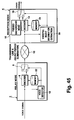
- Figure 45 is a block diagram of a conventional voice coding-and-transmission system for solving the above problem. This diagram is based on the block diagram shown in Japanese Patent Laid-Open No. Hei 2-181552.
- This voice transmitting system forms a set of structures by a transmission node 2 and a reception node 4.
- the transmission node 2 codes a voice signal using a high-efficiency voice encoder 6 and transmits the signal to a transmission line 10 via a changeover switch 8.
- the changeover switch 8 of the transmission node 2 is switched so as to transmit no data to the transmission line 10 with no talk spurt, that is, at a silent time, a silent-period-eliminated voice code is transmitted from the transmission node 2.
- a voice detector 12 detects a voice or silence of a voice signal and switches the changeover switch 8.
- the reception node 4 decodes a voice code sent from the transmission line 10 to a voice signal by a decoder 14 and outputs the signal. While silent period elimination is performed, the changeover switch 16 is switched to the pseudo-background-noise signal generator 18 side and artificial noises are output from the reception node 4.
- a voice/silence information extractor 20 detects voice or silence in accordance with a voice code and switches the changeover switch 16.
- the transmission node 2 is provided with a memory 22 storing a predetermined internal state of the encoder 6, while the reception node 4 is provided with a memory 24 storing the same content with the memory 22.
- the voice detector 12 and the voice/silence information extractor 20 synchronously detect the transition, a reference value for differential processing is set from the memory 22 to the encoder 6 as an internal state in the transmission node 2, and the same reference value for differential processing as that of the encoder 6 is sent from the memory 24 to the decoder 14 as an internal state in the reception node 4.
- the timing in which a talk spurt is detected synchronizes between the transmission node 2 and the reception node 4 and, at this point, both internal states are reset to the same state. Therefore, the internal state of the encoder 6 always coincides with that of the decoder 14 in a voice period and thereby, it is possible to avoid abnormal sound at the head of a talk spurt.
- Figs 47 and 48 There are two methods for connecting the silent-period-eliminating network and the silent period network, as shown in Figs 47 and 48. These Figures illustrates a transmission from the silent-period-eliminating network to the silent period network.
- Figs. 49 and 50 there are two methods for connecting the ATM network and the STM network as shown in Figs. 49 and 50. These Figures illustrates a transmission from the ATM network to the STM network.
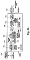
- Figure 47 is a block diagram of a transmission system consisiting of tandem-connecting networks eliminating silent periods and of networks not eliminating silent period connected through a relay node.
- An encoder 32 of a transmission node 30 of this system performs the coding, not eliminating silent periods, and transmits a generated voice code to a transmission line 34 (transmission line B).
- a relay node 36 receives the voice code from the transmission line B, silent-period-eliminates the voice code, and transmits the silent-period-eliminated voice code to the reception node 4 through a transmission line A.
- the relay node 36 decodes the voice code from the transmission node 30 as a voice signal by a decoder 38 and, thereafter, codes the voice signal as a silent-period-eliminated voice code and transmits it to the reception node 4.
- the processing after decoding by the decoder 38, uses the silent-period-eliminated transmission system using the synchronous resetting described for Fig. 45. Therefore, in the case of this transmission system, because the relay node 36 performs decoding once and then coding again, the transmission lines A and B are from the viewpoint of coding greatly independent from each other and, this system is therefore referred to as a tandem connection.
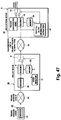
- Figure 48 is a block diagram of a transmission system constituted by connecting networks eliminating silent periods and networks not eliminating silent periods by digital-one-link through a relay node.
- components having corresponding function as those in Fig. 47 are provided with the same symbol and their description is omitted.
- a voice code with no silent period eliminated that is transmitted to the transmission line 34 from the transmission node 30 is silent-period-eliminated by a relay node 50 and transmitted to a reception node 54 through a transmission line 52 (transmission line A).
- a decoder 56 decodes a voice code sent from a transmission line B to restore a voice signal.
- a voice detector 58 detects voice or silence (presence or absence of a talk spurt) in accordance with the voice signal and controls a changeover switch 60.
- the changeover switch 60 connects the transmission line B to the transmission line A only when a voice code with no silent period eliminated from the transmission line B has a talk spurt. When the voice code does not have any talk spurts, it is abandoned and no data is output to the transmission line A. Thereby, a silent-period-eliminated voice code is transmitted to the transmission line A.
- a processing delay unit 62 delays the voice code from the transmission line B by the processing time in the decoder 56 and the voice detector 58 and realize the synchronization between the operation of the changeover switch 60 and the voice code.
- the reception node 54 decodes a silent-period-eliminated voice code transmitted from the relay node 50 to the reception node 54 through the transmission line A as a voice signal by a decoder 64 corresponding to the encoder 32 of the reception node 30 and outputs the decoded voice code.
- a voice/silence information extractor 66 switches a changeover switch 68 toward a pseudo-background-noise signal generator 70 to output artificial noise from the reception node 54.
- the relay node 60 only performs switching. Therefore, though a voice code transmitted to the reception node 54 is silent-period-eliminated, the voice code itself is transmitted from the transmission node 30. Therefore, in the case of this transmission system, the transmission lines A and B are well combined with each other and this is thus referred to as a digital-one-link.
- Figure 49 is a block diagram of a conventional transmission system constituted by tandem-connecting the ATM network and the STM network through a relay node.
- An encoder 73 of a transmission node 72 in the system digitizes a voice signal and performs the coding at a high compression rate.
- a cell composer 74 assorts a sequential voice code coded with the encoder 73 and transmits the code to a transmission line A.
- the transmission line A is the ATM network.
- the voice code is transmitted through the transmission line A in cell units in a burst mode.
- a buffer 76 absorbs a transmission fluctuation of the cell, and then a cell decomposer 77 decomposes the received cell to produce the sequential voice code.
- An vanished cell detector 78 detects a dead cell due to a disuse or a delay in the ATM network, and controls operations of each portion in the relay node 75.
- a decoder 79 decodes a voice code extracted from the cell to an original digital sampling voice signal, for example a PCM (Pulse Code Modulation) voice signal.
- a synchronous incoming unit 80 mates an operation timing between the decoder 73 and the decoder 79.
- An vanished cell compensator 81 compensates a voice signal for the vanished cell.
- a memory 82 stores a latest voice signal for compensating the cell.
- a selector switch 83 is a switch for selecting either the voice signal decoded in the decoder 79 or the voice signal compensated the vanished cell.
- An encoder 84 is same as the encoder 73.
- a transmission line B is the STM network.
- a reception node 85 has a decoder 86 corresponding to the decoder 79.
- the system as shown in Fig. 49 utilizes the following method as one countermeasure against cell vanishing.
- the vanished cell detector 78 monitors cells reaching the relay node 75, detects disappeared cells in the ATM network or those not reaching the relay node 75 within a predetermined period, and sends a control signal based on the detection results to the vanished cell compensator 81 and the selector switch 83.
- the cell composer 74 for example, adds an index representing a sending order to a pay load portion of the cell, and the vanished cell detector 78 monitors whether or not the index is lost.
- the vanished cell compensator 81 interpolates / extrapolates or mutes the lost voice signal based on a past voice signal stored in the memory 82.
- the selector switch 83 chooses between an output of the decoder 79 and an output signal of the vanished cell compensator 81 based on a control signal from the vanished cell detector 78. Chosen signal is reapplied the high efficiency coding with the encoder 84, and is sent to the transmission line B (STM network). Thereby, a voice code with reduced cell vanishing damage is sent from the relay node 75.
- the transmission system has mutually highly independent transmission lines A and B in view of coding. For this reason the system is called the tandem connection system.
- ITU-T Recommendation G.726/727 ADPCM Adaptive Differential Pulse Code Modulation
- ITU-T Recommendation G.728 LD-CELP Low-Delay Code-Excited Linear Prediction
- ITU-T Recommendation G.729 CS-ACELP Conjugate Structure Algebraic Code Excited Linear Prediction
- Figure 50 is a block diagram of a conventional transmission system consisting of digital-one-linking the ATM network and the STM network through a relay node. Components in Fig. 50 having corresponding functions as those in Fig. 49 are provided with the same symbol and their description is omitted.
- a cell including high efficiency voice code which is sent from the transmission node 72 to the transmission line A (ATM network) is decomposed by the relay node 90, remounted to a synchronous frame, and then transmitted to the reception node 85 through the transmission line B (STM network).
- the reception node 85 decodes the voice code, which is transmitted from the relay node 90 through the transmission line B, using the decoder 86 corresponding to the encoder 73 at the transmission node 72, and outputs the decoded voice code.
- the relay node 90 only performs a switching.
- the voice code for transmitting to the reception node 85 is a signal sent from the transmission node 72 itself. Therefore, the transmission system has mutually highly integrated transmission lines A and B in view of encoding. This is a reason that the system is called the digital-one-link system.
- Connecting the transmission lines A and B according to a tandem connection or digital-one-link has the following problems.
- a voice code from the transmission node 30 is once decoded to a voice signal and then transmitted in accordance with the silent period elimination using synchronous resetting. Therefore, the internal state of the encoder 6 of the relay node 36 coincides with that of the reception node 4 and abnormal sound is avoided as described above.
- a voice signal input to a transmission node is coded and decoded twice before it is output from a reception node.
- the voice code for transmitting to the reception node 85 is the same as the voice code generated at the transmission node 72. Therefore, voice-signal quality degradation due to an accumulation of quantization errors is prevented.
- the relay node only switching is performed and extracting voice information from the voice code is not performed. Normally, it is difficult to directly compensate for the vanished voice code by a simple method such as interpolation / extrapolation / assumption without decoding the voice code applied the high efficiency coding.
- the voice information transmitted to the reception node 85 is discontinuous to induce an abnormal sound at the reception node 85 making a listener uncomfortable.
- a missing phoneme remarkably lowers speech comprehension.
- the information about the cell vanishing detected in the relay node may be transmitted to, for example, the STM network by providing a signal line separately, and other mechanism for a countermeasure of the cell vanishing may be provided at the reception node 85.
- An object of the present invention is to provide a voice coding-and-transmission system solving the above problems and realizing a high-quality voice transmission at a realistic cost, in which an ATM network and a STM network are coexisted and an existing silent-period-elimination transmission network is housed in a high-efficiency transmission network using a silent period eliminating art together with a high-efficiency voice coding art using a differential coding.
- a voice coding-and-transmission system related to the first aspect of the present invention is characterized in that a relay node includes a relay decoder for extracting voice information included in a voice signal from an original voice code, a relay control circuit for discriminating between a voice period and a silent period of said voice signal in accordance with said voice information and outputting a relay control signal for controlling operations of a relay node in accordance with a discrimination result, an coding reference value determination circuit for determining a reference value for differential coding at the start of voicing which is the timing of change from said silent period to said voice period in accordance with said relay control signal, a relay encoder for starting said differential coding of said voice information in accordance with said reference value and generating relay voice codes for at least a certain change period, and a silent-period elimination circuit for receiving said original voice code and said relay voice code and outputting said relay voice code to said second transmission line during said change period and said original voice code to the second transmission line during a voice period after said change period in accordance with said
- a relay encoder and a reception decoder obtain a differential-coding reference value (referred to as a reference value at start of voicing) from respective coding reference-value determination or decoding reference-value determination circuits.
- the differential coding is a method for fetching and coding a difference between reference values given by past coding or decoding.
- the number of reference values is not limited to one, but it is possible to use a reference value for each of various parameters showing a voice signal.
- a reference value at start of voicing to be determined by an coding-reference value determination circuit and that to be determined by a decoding reference-value determination circuit respectively are made to correspond to each other so that a reception decoder can regenerate voice information input to a relay encoder and the reference values are generally equal to each other.
- the encoder and decoder in which their reference values are made to correspond to each other it is assumed that their internal states coincide. If internal states do not coincide with each other, abnormal sound may be output from a reception node. However, because the internal states of the relay encoder and reception decoder are synchronized and initialized to coincide with each other, no abnormal sound is produced.
- a silent-period elimination circuit transmits a relay voice code which is an output of a relay encoder to a reception decoder via the second transmission line within a predetermined change period from the start of voicing.
- the silent-period elimination circuit directly transmits an original voice code transmitted from the transmission node to the reception decoder during a voiceful period after the change period. That is, after the change period, a voice signal is differential-coded by the transmission node and then regenerated through decoding in the reception node without undergoing the coding/decoding in the change period by the relay node. Therefore, the coding/decoding frequency is smaller than that in the change period and the number of quantization errors decreases.
- voice quality degradation due to abnormal sound is prevented by tandem connection when the internal state of the transmission node dissociates from that of the reception decoder, and voice quality degradation due to accumulation of quantization errors such as in tandem connection is prevented by digital-one-link when their internal states approximate each other.
- the degree of approximation between the internal state of the transmission node and that of the reception decoder is further improved as the time after the start of voicing increases and the abnormal-sound suppression effect is improved.
- the period of degradation due to quantization errors by tandem connection also increases.
- the transient period is determined in accordance with the balance between suppression of abnormal sounds and lengthening of the period in which voice quality degradation due to quantization errors is suppressed.
- voice quality degradation due to abnormal sound at the head of a talk spurt is prevented by tandem connection during only a short change period until the difference between the internal state for coding in a transmission node and the internal state of a decoder of a reception node converge immediately after the talk spurt is detected, and voice quality degradation due to accumulation of quantization errors such as in the tandem connection is prevented by performing digital-one-link during most voice period after the difference between these internal states completely converges. That is, there are advantages that abnormal sound produced at the head of a talk spurt is suppressed and moderated, rugged feeling due to abnormal sound is vanished, degree of voice comprehension is improved, and, moreover, voice quality degradation due to continuous tandem connection is prevented.
- a voice coding-and-transmission system related to the second aspect of the present invention is characterized in that a relay node includes a relay decoder for extracting voice information included in a voice signal from an original voice code, a relay control circuit for discriminating between a voiceful period and a silent period of said voice signal in accordance with said voice information and outputting a relay control signal for controlling operations of a relay node in accordance with a discrimination result, a voice code corrector for outputting a corrected voice code obtained by replacing an original voice code of a portion of a voice signal output from a reception node with a voice code for suppressing said abnormal sound in accordance with said voice information when said abnormal sound may be produced, and a silent period elimination circuit for receiving said original voice code and said corrected voice code and outputting said corrected voice code to said second transmission line within a predetermined transient period from the start of voicing which is the timing of change from said silent period to said voiceful period and outputting said original voice code to said transmission line during a voice period after said change period in accord
- a corrected voice code causes little divergence, even in unstable coding/decoding systems with different internal states output from a relay node in a change period with a high possibility of voice signal divergent and abnormal sound production.
- the corrected voice code is obtained by suppressing values of parameters related to gain among voice parameters.
- the voice coding-and-transmission system related to the second aspect of the present invention also has an advantage that no special consideration or operation is necessary for internal states of relay and reception nodes in order to suppress abnormal sound, in addition to the advantage of the first aspect, because the relay node outputs a corrected voice code for suppressing abnormal sound at the time of tandem connection in a change period and the reception node decodes the corrected voice code.
- a voice coding-and-transmission system related to the third aspect of the present invention is characterized in that a voice code includes a gain code made to correspond to gain information in voice information in accordance with codebooks which are tables for correlating a quantized gain value and a gain code, a relay node includes a relay decoder for fetching voice information included in a voice signal from an original voice code, a relay control circuit for discriminating between a voiceful period and a silent period of said voice signal in accordance with said voice information and outputting a relay control signal for controlling operations of a relay node in accordance with a discrimination result, a suppression codebook which is one of said code books, a relay encoder for performing said differential coding of said voice information by obtaining a gain code from said suppression codebook to generate a relay voice code, and a silent-period elimination circuit for receiving said original voice code and said relay voice code and outputting said relay voice code to said second transmission line during a predetermined change period which is the timing of change from said silent period to said voiceful
- a relay encoder generates a relay voice code causing little divergence even in an unstable coding/decoding system with different internal states by using a suppression codebook.
- a reception node prevents abnormal sound by outputting the relay voice code from a relay node.
- several ranges are formed for gain values in voice information and each range is assigned one gain value as a quantized value.
- a gain code is made to correspond to the quantized value.
- a relay encoder and a reception decoder use the same suppression codebook and a quantized gain value is obtained at the reception decoder side for an actual gain value in voice information serving as an input of the relay encoder.
- the voice coding-and-transmission system related to the third aspect of the present invention also has an advantage that no special consideration or operation is necessary for internal states of a relay node and a reception node in order to suppress abnormal sound, in addition to the advantage of the first aspect, because tandem connection is performed which delivers a voice code for suppressing divergence of the system by changing gain codebooks used by a relay node and a reception node.
- the system has advantages that the structure is simple because only a few control signals necessary for controlling operations are used, decreasing the processing load such as arithmetic.
- a voice coding-and-transmission system related to the fourth aspect of the present invention is characterized in that a reception node includes a reception control circuit for discriminating between start of voicing and end of voicing in accordance with a silent-period-vanished voice code and outputting a reception control signal for controlling operations of a reception node in accordance with a discrimination result, a voice code corrector for outputting a corrected voice code obtained by replacing a silent-period-vanished voice code of a portion of a voice signal output from said reception node with a voice code for suppressing abnormal sound in accordance with said silent-period-vanished voice code when said abnormal sound may be produced, a decoded input selector for receiving said silent-period-vanished voice code and said corrected voice code and outputting said corrected voice code within a predetermined change period from the start of said voicing and said silent-period-vanished voice code up to the end of said voicing after said change period in accordance with said reception control signal, and a reception decode
- a corrected voice code causing little divergence even in an unstable coding/decoding system with different internal states is generated by a voice code corrector in a reception node during a change period with a high possibility that a voice signal diverges and abnormal sound is produced and a silent- period-vanished voice code received by the reception node is replaced with the corrected voice code.
- the corrected voice code is obtained by suppressing values of parameters related to gain among voice parameters. Thereby, abnormal sound is prevented in the reception node.
- the voice coding-and-transmission system related to the fourth aspect of the present invention also has an advantage that a relay node does not require the function of tandem connection, in addition to the advantage of the first aspect, because a corrected voice code is generated in a reception node and tandem connection during a change period is falsely realized in the reception node. Thereby, an advantage is also obtained that no special consideration or operation is necessary for internal states of the relay node and reception node in order to suppress abnormal sound. Moreover, an advantage is obtained that the structure of the relay node is simplified and it is unnecessary to improve a conventional structure.
- a voice coding-and-transmission system related to the fifth aspect of the present invention is characterized in that a relay node includes a relay decoder for extracting voice information included in a voice signal from an original voice code, a relay control circuit for discriminating between a voiceful period and a silent period of said voice signal in accordance with said voice information and outputting a relay control signal for controlling operations of a relay node in accordance with a discrimination result, a relay encoder for coding voice information at the present time and generating a relay voice code, and a silent-period elimination circuit for receiving said original voice code and said relay voice code and outputting said relay voice code to said second transmission line within a predetermined change period from the start of voicing which is the timing of change from said silent period to said voice period and said original voice code to said second transmission line during a voice period after said change period in accordance with said relay control signal to synthesize said silent-period-vanished voice code; a reception node includes a reception control circuit for deciding the start of said
- a relay encoder codes voice information decoded by a relay decoder in accordance with voice information at the present time without depending on the non-differential coding system, that is, past coding or decoding.
- a reception node decodes a relay voice code output from a relay encoder as a voice signal by a second reception decoder, corresponding to the coding system of the signal, and outputs the signal.
- a reference-value adapting section codes a voice signal sent from the second reception decoder by the same differential coding system as in the case of a transmission node and supplies a first reception decoder corresponding to the coding system.
- the relay node connects the transmission node with the reception node by digital-one-link and the reception node starts decoding by the first reception decoder synchronously with the connection between the nodes after the change period.
- the tandem connection between the relay encoder and the second reception encoder in the change period uses the non- differential coding system, the coding reference value determination circuit and decoding reference value determination circuit for performing operations such as synchronous resetting of the relay encoder and second reception decoder at start of voicing are unnecessary.
- tandem connection according to the non-differential coding system is performed to prevent voice quality from deteriorating due to abnormal sound when the internal state of the transmission node dissociates from that of the first reception decoder and digital-one-link is used when their internal states approach each other due to working of the reference-value adapting section.
- a voice coding-and-transmission system related to the sixth aspect of the present invention is characterized in that a relay node includes a relay decoder for fetching voice information included in a voice signal from an original voice code, a relay control circuit for discriminating between a voice period and a silent period of said voice signal in accordance with said voice information and outputting a relay control signal for controlling operations of a relay node in accordance with a discrimination result, a delay circuit for delaying said original voice code by a predetermined delay time, and a silent-period elimination circuit for performing silent period elimination by outputting said original voice code from said delay circuit to said second transmission line during said voiceful period in accordance with said relay control signal; and a reception node includes a reception control circuit for deciding the start of said voicing in accordance with a silent-period-vanished voice code and outputting a reception control signal for controlling operations of a reception node in accordance with a decision result, and a reception decoder for applying said decoding corresponding to said differential
- the timing of a relay control signal in accordance with the voice detection by a relay control circuit precedes the timing of an original voice code to be input to a silent period elimination circuit.
- a silent period according to a delay value of a delay circuit is provided at the head of a silent-period-vanished voice code as a hangover period.
- a reception control circuit decides the start of voicing in accordance with a transmitted silent-period-vanished voice code and the start of said voicing precedes the timing of change from a silent state to a voice state of an actual voice signal.
- a voice code corresponding to silence is input to a reception decoder during the hangover period after the start of said voicing.
- the time base of the voice code is shifted by the delay circuit so that the state change which is a process when the internal state of the reception decoder approximates the internal state of coding of a transmitting node is performed in a silent period. Therefore, even for an coding/decoding system whose operations become unstable due to incoincidence between internal states, oscillation is not performed and little abnormal sound is produced.
- the voice coding-and-transmission system related to the sixth aspect of the present invention it is possible to suppress abnormal sound by a very simple structure in which a delay circuit is set to a relay node and moreover, connection is always made by digital-one-link and voice quality degradation due to accumulation of quantization errors does not occur because a silent period (hangover period) is included in the head of a silent- period-vanished voice code to be transmitted to a reception node by setting a delay circuit to a relay node and delaying the transmission of a voice code and convergence of the difference between the internal states of the relay node and a reception decoder is previously performed.
- a voice coding-and-transmission system related to the seventh aspect of the present invention is characterized in that a relay node includes a relay decoder for fetching voice information included in a voice signal from an original voice code in accordance with a reference value for decoding corresponding to differential coding, a relay control circuit for discriminating between a voice period and a silent period of said voice signal in accordance with said voice information and outputting a relay control signal for controlling operations of a relay node, a delay circuit for delaying said original voice code by a predetermined delay time, a reference state encoder for outputting a reference state code obtained by coding said reference value of said relay decoder, and a silent-period elimination circuit for receiving an original voice code output from said delay circuit and said reference state code and outputting said state code within said delay time from start of voicing which is the timing of change from said silent period to said voice period and said original voice code after said delay time passes in accordance with said relay control signal to synthesize a silent-period-vanished voice code.
- a reception node includes a reception control circuit for deciding the start of said voicing in accordance with said silent-period-vanished voice code and outputting a reception control signal for controlling operations of a reception node in accordance with a decision result, a reference state decoder for decoding said reference state code and outputting said reference value, and a reception decoder for starting said decoding of said silent-period-vanished voice code in accordance with said reference value and outputting said voice signal.
- the internal state of the relay decoder that is: the reference state code obtained by coding the reference value for differential coding
- the reference state decoder decodes the reference state code and forcibly initializes the reception decoder.
- the voice coding-and-transmission system related to the seventh aspect of the present invention uses the above hangover period by setting the delay circuit to the relay node and transmits a reference state code obtained by coding the internal state of the relay decoder during the hangover period to the reception decoder to make the internal states of the transmission node and reception node forcibly coincide with each other.
- a reference state code obtained by coding the internal state of the relay decoder during the hangover period to the reception decoder to make the internal states of the transmission node and reception node forcibly coincide with each other.
- a voice coding-and-transmission system related to the eighth aspect of the present invention is characterized in that a relay node includes a relay control circuit for detecting cell vanishing in an asynchronous transfer mode transmission line based on received cells, and outputting a relay control signal for controlling operations of the relay node in accordance with a detection result; a voice code repairing portion for compensating an original voice code which is lost due to the cell vanishing based on the original voice code received and for generating a relay voice code; and an output switching unit for switching outputs of the original voice code and the relay voice code in the synchronous transfer mode transmission line based on the relay control signal, outputting the relay voice code when detecting the cell vanishing and outputting the original voice code when detecting no cell vanishing.
- the ATM network and the STM network are tandem-connected only for a period in which the cell is vanished, and are digital-one-link-connected for a normal period in which the cell is not vanished.
- voice quality degradation due to accumulation quantization errors from the tandem connection is prevented.
- a compensation processing of the vanished cell is realized under the tandem-connection, thereby the degradation of the voice quality due to the vanished cell is prevented.
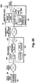
- FIG. 1 is a block diagram of the voice coding-and-transmission system of this embodiment.
- a transmission node 100 outputs an original voice code obtained by coding a voice signal.
- the original voice code is a differential-coded high-efficiency voice code, it is not silent-period-vanished.
- the original voice code is transmitted to a transmission line B. That is, the transmission line B represents a transmission network in which silent period elimination is not performed.
- a transmission line A to which a reception node 102 is connected represents a transmission network in which silent period elimination is performed.
- a relay node 104 connects these two transmission networks, receives an original voice code from the transmission node 100 through the transmission line B, and converts the voice code to a silent-period- vanished voice code to output it to the transmission line A.
- the reception node 102 decodes the silent-period-vanished voice code and outputs a voice signal.
- the transmission node 100 has an encoder (coding unit) 106 for differential-coding an input voice signal.
- the encoder 106 generates an original voice code which is a high-efficiency voice code.
- the high-efficiency voice code transmitted from the transmission node 100 to the relay node 104 through the transmission line B is decoded as a voice signal by a decoder (relay decoder) 108.
- a voice detector 110 detects presence or absence of a talk spurt in accordance with the voice signal, that is, discriminates between a voice period and a silent period and outputs a signal (relay control signal) for controlling operation modes of the relay node in accordance with a discrimination result.
- the relay node has three operation modes switched by the voice detector 110. These operation modes are described below by referring to Fig. 2.
- Figure 2 is a waveform diagram of a voice signal output from a decoder 108.
- the y axis represents signal level and x axis represents time.
- the voice detector 110 divides the voice signal into three periods (sections) corresponding to operation modes and controls operations of the relay node 104. First, the period in which no talks part is detected from a high-efficiency voice code input to the relay node 104 is assumed as mode 1. Second, the period for some tens to hundreds of milliseconds after a talk spurt is detected (this period is referred to as a change period or a transient period) is assumed as mode 2. Third, the period in which talk spurts are continuously detected after mode 2 is assumed to be mode 3.
- the voice detector 110 supplies a control signal reflecting the above-described operation-mode decision results to a silent period elimination circuit 112.
- the relay node 104 has two routes for connecting the transmission lines B and A.
- the first route comprises the decoder 108 and the encoder (relay encoder) 114 and the second route passes a processing delay unit 116.
- the silent period elimination circuit 112 has a built-in switch for switching three states of voice code outputting to the transmission line A through either of the first and second routes or outputting no voice code by not connecting the transmission line A to any object.
- the processing delay unit 116 has a delay time equal to a signal delay produced in the route comprising the decoder 108 and the encoder 114 and arranges the signal timing between the first and second routes.
- the silent period elimination circuit 112 eliminates a voice code during silent periods by outputting no data to the transmission line A in mode 1 with "no" talk spurt. Moreover, the silent period elimination circuit 112 adds the information necessary for the mode decision (mode information) in the reception node 102 to a voice code. The mode information shows the start or end of a voice period. Thus, a silent period eliminator 112 synthesizes a silent-period-vanished voice code and transmits the code to the transmission line A.
- a memory 118 is described later.
- a voice/silence information extractor 120 extracts mode information from a silent-period-vanished voice code and outputs a signal for controlling operation modes of a reception node (reception control signal).
- the reception node 102 includes a decoder (reception decoder) 122 and a pseudo background noise generator (pseudo-background-noise signal generator) 124 for generating artificial noises.
- a changeover switch 126 directs output of a signal from the decoder 122 or generator 124.
- a memory 128 is described later.
- the relay node 104 connects the changeover switch in the silent period eliminator 112 to a terminal 112b. Because the terminal 112b is not connected to either of the first or second routes, no high-efficiency voice code is output to the transmission line A in this case.
- the voice detector 110 constantly operates because it is necessary to continuously monitor the change of modes. Because the voice detector 110 performs mode decision by using a voice signal output from the decoder 108 as its input, the voice signal must always be supplied. Therefore, the decoder 108 also operates constantly.
- the encoder 114 need not be operated because it is unnecessary to supply a high-efficiency voice code output from the encoder 114 to other block or transmit it to a reception node in this mode.
- the voice/silence information extractor 120 decides mode 1 in accordance with a silent-period-vanished voice code transmitted from the transmission line A. This decision is made by obtaining the information showing the end of a voice period added to the last of a group of silent-period-vanished voice codes (the last packet or cell when silent-period-vanished voice codes are transmitted by being divided into a plurality of packets or cells) and thereby deciding mode 1 after the final code.
- the changeover switch 126 By receiving a control signal reflecting the information of being mode 1, the changeover switch 126 is switched to the terminal-126a side, pseudo-background noises of the pseudo background noise generator 124 are output from the reception node 102, and a natural silent state is transferred to a receiver.
- the voice detector 110 when the voice detector 110 detects that operation modes change from 1 to 2, it transmits to the encoder 114 a control signal form notifying that a silent state changes to a voice state.
- the encoder 114 responds to the control signal, loads the data stored in a memory 118 in a memory inside of the encoder 114 as a reference value for the differential coding of various voice parameters, and starts coding a voice signal output from the decoder 108 in accordance with the reference value. That is, the memory 118 determines a reference value of the encoder 114.
- a changeover switch of the silent period eliminator 112 is switched to the terminal-112c side.
- the voice/silence information extractor 120 extracts mode information from a silent-period-vanished voice code transmitted from the transmission line A and detects that operation modes change from 1 to 2.
- the voice/silence information extractor 120 transmits a control signal for notifying that a silent state changes to a voice state to the decoder 122.
- the decoder 122 responds to the control signal to load the data stored in the memory 128 in a memory inside of the decoder 122 as a reference value for the differential coding or decoding of various voice parameters.
- the voice/silence information extractor 120 transmits the same signal to the changeover switch 126.
- the changeover switch 126 is switched to the terminal-126b side in accordance with the control signal. That is, the memory 128 determines a reference value of the decoder 122.
- the voice detector 110 decides mode 3
- a changeover switch in the silent period eliminator 112 is switched to the terminal-112a side and a high-efficiency voice code sent from the encoder 106 of the transmission node 100 is output directly to the transmission line A.
- the voice detector 110 is continuously operated because it is necessary to monitor the change of modes. Because the voice detector 110 performs mode decision by using a voice signal output from the decoder 108 as its input, the voice signal must be supplied to the voice detector 110. Therefore, the decoder 108 also continuously operates. However, the encoder 114 need not be operated because it is unnecessary to supply a high-efficiency voice code generated by the encoder 114 to other block or transmit the code to a reception node in this mode.
- a higher-quality decoded voice can be obtained by using a previously-calculated predictive filter factor and memory belonging to predictive filter adaptive means (e.g. auto-correlation function) or memory belonging to adaptive gain or gain adaptive means.
- predictive filter adaptive means e.g. auto-correlation function
- the data calculated and stored when coding/decoding background noises is the most suitable from the viewpoint of the acoustic quality.
- this value depends on the coding system used.
- an advantage almost equal to that of the above embodiment can be obtained even if using other value. That is, it is the essence of the present invention that the timings of control signals generated by the voice detector 110 and voice/silence information extractor 120 coincide each other and thereby, the same internal state is sent to the encoder 114 and decoder 122 and indefinite components due to past data are vanished.
- the voice coding-and-transmission system of this embodiment makes it possible to avoid quality degradation by limiting the period for performing tandem connection for which it is known to cause voice quality degradation to a short time of a transient period in which a silent state changes to a voiceful state and connecting most talk spurts by digital-one-link and fully bring out the performances of the high-efficiency voice coding system. Moreover, it is possible to decrease the processor processing load and the hardware scale of the relay node 104.
- the value of tens to hundreds of milliseconds is shown as the continuous time (change time) of mode 2.
- the base of this value conforms to the following empirical rule.
- the time required from a mode change up to a complete coincidence between internal states is some tens or hundreds of milliseconds. It is obvious that it is predicted that the above value changes depending on the high-efficiency coding system used. Therefore, it is important to set a change period corresponding to each coding system.
- Figure 3 is a state change diagram showing the change between the modes described above. Only the directions shown by arrows are allowed for the change between three modes and a change other than the above change is an inhibited change or a change which cannot physically be considered.
- ITU Recommendation G.728 is applied to a high-efficiency coding system.
- the present invention is not restricted to the coding system.
- the present invention can be applied to every voice coding system using past coding/decoding result referred to as the differential coding system in this case.
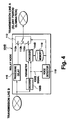
- FIG. 4 is a block diagram of a relay node for explaining the second embodiment of the present invention.
- This embodiment is obtained by improving the relay node of the voice coding-and-transmission system of the embodiment 1.
- the processing load and hardware scale of the relay node can be decreased.
- the transmission node 100 and the reception node 102 are not illustrated because they are the same as those of the embodiment 1; only a relay node is shown.
- a component having the same function as that of the component described for the embodiment 1 is provided with the same symbol as in Fig. 1 and its description is not repeated.
- the character B is added to its symbol in Fig. 1 so that how the component corresponds to the component of the embodiment 1 can easily be understood.
- a decoder 108B decodes a voice signal and outputs some of the adaptive parameters.
- An adaptive parameter is generated in high-efficiency coding such as ADPCM, which is a voice parameter for constituting a voice signal.
- An encoder 114B receives the voice signal and adaptive parameters. In the case of the encoder 114B, it is possible to omit the processing for generating input adaptive parameters. Most operations of this voice coding-and-transmission system are the same as those of the embodiment 1 except that some of adaptive parameters are supplied to the encoder 114B from the decoder 108B. Thereby, some adaptive differential processings can be omitted for the encoder 114B.
- FIG. 5 is a block diagram of a relay node for explaining the third embodiment of the present invention.
- This embodiment is obtained by improving the relay node of the voice coding-and-transmission system of the embodiment 1 or 2.
- the processing load and hardware scale of the relay node can be decreased.
- the transmission node 100 and the reception node 102 are not illustrated because they are the same as those of the embodiment 1 and only the relay node is shown.
- a component having the same function as that explained in the embodiment 1 is provided with the same symbol and its description is not repeated.
- the character C is added to its symbol in Fig. 1, so that how the component corresponds to the components of the embodiment 1 and embodiment 2 can easily be understood.
- a parameter separator 108C is constituted by omitting some processings of the decoder 108B in Fig. 4.
- the parameter separator 108C is not provided with a function for decoding a voice signal in a complete form, but it is provided with a parameter extracting function.
- the parameter separator 108C outputs an excitation signal and a parameter to the encoder 114C and outputs pitch information (or excitation signal information) to a voice detector 110C.
- the voice detector 110C detects voices in accordance with the pitch information (or excitation signal information). Other operations of this voice coding-and-transmission system are the same as those of the embodiment 2.
- the relay node 104C uses the voice detector 110C and encoder 114C having a structure requiring no voice signal input instead of the detector 110B and encoder 114B.
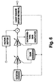
- FIG. 6 is a block diagram of the encoder 114C for performing coding in accordance with an excitation vector without using any voice signal input.
- a vector to be referenced is only shifted from a voice signal to an excitation signal and the structure is the same as that of the original encoder, except that a synthesizing filter and its adaptive processing are omitted. Therefore, the compatibility with the original ITU Recommendation G.728 coding system is assured. Also, it is easy to change the structure of the voice detector 110C to a structure based on an excitation signal because voice power is strongly reflected on excitation gain. Moreover, it is possible to improve the accuracy by extracting pitch information from an excitation signal.
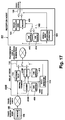
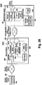
- Figure 7 is a block diagram of the voice coding-and-transmission system of the fourth embodiment of the present invention. This embodiment is obtained by improving the relay node and reception node of the voice coding-and-transmission system of the embodiment 1.
- a component having the same function as that described for the embodiment 1 is provided with the same symbol and its description is not repeated.
- the character D is added to the symbol in Fig. 1 so that how the component corresponds to that of the embodiment 1 can easily be understood.
- a relay node 104D has a pseudo background noise generator 140.
- An input from the encoder 114 is connected to either the pseudo background noise generator 140 or the decoder 108 by a changeover switch 142.
- an output from a pseudo background noise generator 144 is coded by an encoder (noise encoder) 146.
- An input for the decoder 122 is connected to either the encoder 146 or the transmission line A by a changeover switch 148.
- a voice code from the transmission line B is once decoded as a voice signal by the decoder 108 in the relay node 104D.
- the voice detector 110 detects presence or absence of a talk spurt in accordance with the voice signal and decides an operation mode of the relay node 104D in accordance with a detection result.
- An coding/decoding system of the present invention has three operation modes. However, description of these operation modes is omitted because the operation modes are the same as those described for the embodiment 1.
- the operation in mode 3 (voiceful state) is completely the same as the operation in mode 3 shown in the embodiment 1. In this case, it is possible to stop the encoder 146 at the reception node.
- the changeover switch 142 is connected to a terminal 142a and a changeover switch 112 is connected to the terminal 112b. Therefore, a pseudo background noise output from the pseudo background noise generator 140 is input to the encoder 114.
- the encoder 114 receives the input of the pseudo back ground noise and codes the noise.
- a signal obtained by high-efficiency-coding of the pseudo background noise is output from the encoder 114 and, moreover, internal variables of a filter factor and the like are adaptively updated. This operation is previously shown by taking ITU Recommendation G.728 as an example.
- the voice detector 110 is always operated because it is necessary to continuously monitor the mode changes. Moreover, in the reception node 102D, the voice/silence information extractor 120 fetches mode information from a silent-period-vanished voice code transmitted from the transmission line A, extracts the information showing that the decision result of the voice encoder 110 is switched from mode 3 to mode 1, and outputs a control signal according to the information to the changeover switch 148 and the encoder 146. The changeover switch 148 is switched to the terminal-148a side in accordance with the control signal.
- the encoder 146 loads the internal variables of the decoder 122 (e.g. synthesizing filter memory and adaptive gain) in a predetermined area of the encoder 146 by responding to the control signal and also makes its internal state coincide with that of the decoder 122. Thereafter, the encoder 146 starts coding by using a pseudo background noise output from the pseudo background noise generator 144 as its input.
- the internal variables of the decoder 122 e.g. synthesizing filter memory and adaptive gain
- the decoder 122 operates by using a high-efficiency background noise code output from the encoder 146 as its input.
- a high-efficiency background noise code output from the encoder 114 (the code is not actually output to a transmission line) must be completely the same as that output from the encoder 122.
- a pseudo background noise output from the pseudo background noise generator 144 must be the same as a pseudo background noise output from the pseudo background noise generator 140 in the relay node 104D.
- the pseudo background noise generator 140 supplies a reference value for differential coding to the encoder 114 when changing from mode 1 to mode 2 (that is, at start of voicing) and the pseudo background noise generator 144 and the encoder 146 supply a reference value for differential coding to the decoder 122 at start of voicing).
- the incoincidence between the internal states of the encoder 114 of the relay node 104D and the decoder 122 of the reception node 102D does not occur and abnormal sound at the change of operation modes from 1 to 2 can be avoided.
- the voice detector 110 detects the head of a talk spurt, it transmits a control signal to the changeover switch 142 and the silent period eliminator 112.
- the changeover switch 142 By responding to the control signal, the changeover switch 142 is switched to the terminal-142b side and a changeover switch in the silent period eliminator 112 is switched to the terminal-112c side.
- a voice signal decoded by the decoder 108 is coded as a high-efficiency voice code again by the encoder 114 and the high-efficiency voice code is output to the transmission line A from the relay node 104D.
- the voice/silence information extractor 120 detects the change to operation mode 2, it outputs a control signal to the changeover switch 148.
- the changeover switch 148 is switched to the terminal-148b side by the control signal.
- the decoder 122 decodes an output of the encoder 114 input from the transmission line A.
- the internal states of the encoder 106 and the decoder 122 of the transmission node 100 approach each other. Therefore, no abnormal sound is produced, even if operation modes are thereafter changed from 2 to 3.
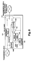
- FIG 8 is a block diagram of a relay node for explaining the fifth embodiment of the present invention.
- This embodiment is obtained by applying the same improvement as that shown in the embodiment 2 to the relay node of the embodiment 4. That is, a relay decoder and relay encoder use the decoder 108B and the encoder 114B having the same function as that of the embodiment 2 respectively.
- the decoder 108B decodes a voice signal and outputs some adaptive parameters. In the case of the encoder 114B, it is possible to omit the processing for generating these adaptive parameters. This improvement decreases the processing load and hardware scale of the relay node.
- the decoder 108B decodes a voice signal and outputs some adaptive parameters.
- An adaptive parameter is a voice parameter to be generated in high-efficiency coding such as ADPCM to form a voice signal.
- the encoder 114B receives the voice signal and adaptive parameters. In the case of the encoder 114B, it is possible to omit the processing for generating input adaptive parameters. Most operations of this voice coding-and-transmission system are the same as those of the embodiment 4, except that the decoder 108B fetches adaptive parameters and the encoder 114B uses them similar to the case of the embodiment 2.
- Figure 9 is a block diagram of the voice coding-and-transmission system of the sixth embodiment of the present invention. This embodiment is obtained by further applying the same improvement as that shown in the embodiment 3 to the relay node of the embodiment 5. That is, a relay decoder, relay encoder, and voice detector use the parameter separator 108C, encoder 114C, and voice detector 110C having the same function as the embodiment 3 respectively.
- the parameter separator 108C fetches only some of the adaptive parameters included in a voice signal while the encoder 114 generates a voice code instead of a complete voice signal in accordance with some of the adaptive parameters. This improvement further decreases the processing load and hardware scale of the relay node.
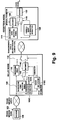
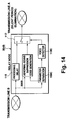
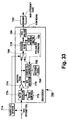
- FIG. 10 is a block diagram of the voice coding-and-transmission system of the seventh embodiment of the present invention. This embodiment is obtained by improving the relay node and the reception node of the voice coding-and-transmission system of the embodiment 1 of the present invention.
- a component having the same function as that described for the embodiment 1 is provided with the same symbols as in Fig. 1 and its description is not repeated.
- the character G is added to the symbol in Fig. 1 so that how the component corresponds to that of the embodiment 1 can easily be understood.
- a relay node 104G and a reception node 102G have respective task controllers 160 and 162.
- the task controller 160 controls operations of the encoder 114 in accordance with a control signal output from the voice detector 110.
- the task controller 162 controls the decoder 122 in accordance with a control signal output from the voice/silence information extractor 120.
- the decoder 108 once decodes a voice code sent from the transmission node 100.
- the voice detector 110 detects presence or absence of a talk spurt in accordance with the voice signal and decides an operation mode of the relay node in accordance with a detection result.
- the coding/decoding system of the present invention has three operation modes. However, description of the operation modes is omitted because the operation modes are the same as those described for the embodiment 1.
- mode 3 is completely identical to that mode 3 shown in the embodiment 1.
- the encoder 114 of the relay node 104G codes a voice signal output from the decoder 108.
- the voice detector 110 when the voice detector 110 detects the change of operation modes from 3 to 1, it transmits a control signal to the silent period eliminator 112.
- a changeover switch in the silent period eliminator 112 responds to the control signal to connect with the terminal 112b and stop the output of a voice code from the relay node 104G.
- the control signal is sent to the task controller 160.
- the task controller 160 responds to the control signal and sends a control signal for stopping the coding operation of the encoder 114 to the encoder 114.
- the encoder 114 responds to the control signal to stop the coding operation while holding the contents (e.g. synthesizing filter factor and adaptive gain) in its internal memory.
- the encoder 114 does not perform any coding while holding the contents of the internal memory as long as the state of mode 1 continues since the mode change.
- the voice/silence information extractor 120 fetches mode information from a silent-period-vanished voice code transmitted from the transmission line A and sends a control signal corresponding to the change of operation modes from 3 to 1 to the changeover switch 126 and the task control section 162.
- the changeover switch 126 is switched to the terminal-126a side.
- the task controller 162 responds to the control signal to stop the decoding operation of the decoder 122 while holding the contents of the internal memory.
- the decoder 122 does not perform decoding at all while holding the contents of the internal memory as long as the state of mode 1 continues since the mode change.
- the voice detector 110 when the voice detector 110 detects the change of operation modes from 1 to 2, it switches a changeover switch in the silent period eliminator 112 to the terminal-112c and sends a control signal for notifying the change of operation modes from 1 to 2 to the task controller 160.
- the task controller 160 responds to this control signal and outputs a control signal for restarting coding to the encoder 114.
- the encoder 114 responds to the control signal to restart coding by using the contents (e.g. synthesizing filter factor and adaptive gain) held in the internal memory since the change of operation modes from 3 to 1 without initializing the contents as reference values for differential coding/decoding.
- a high-efficiency voice code output from the encoder 114 is output to the transmission line A from the relay node and transmitted to the reception node 102G.
- the voice/silence information extractor 120 fetches mode information from a silent-period-vanished voice code transmitted from the transmission line A and transmits a control signal corresponding to the change of operation modes from 1 to 2 to the changeover switch 126 and the task control section 162.
- the changeover switch 126 is switched to the terminal-126b side in accordance with the control signal.
- the task controller 162 responds to the control signal and outputs a control signal for restarting decoding to the decoder 122.
- the decoder 122 responds to the control signal to restart decoding by using the contents held in the internal memory since the change of operation modes from 3 to 1 as the reference values for differential coding/decoding without initializing the contents.
- the decoder 122 decodes an output of the encoder 114 of the relay node 104G and outputs a voice signal.
- the task controller 160 determines a reference value for differential coding at the change of the encoder 114 to mode 2 (that is, at start of voicing) and the task controller 162 determines a reference value for differential coding at start of voicing for the decoder 122.
- Operations of this embodiment in mode 2 are basically the same as those of the embodiment 1.
- the voice detector 110 detects the head of a talk spurt, it sends a control signal to the silent period eliminator 112.
- a changeover switch in the silent period eliminator 112 is switched to the terminal-112c side.
- a voice signal decoded by the decoder 108 is coded as a high-efficiency voice code again by the encoder 114 and the high-efficiency voice code is output to the transmission line A from the relay node 104G.
- the voice/silence information extractor 120 detects the change to operation mode 2, it outputs a control signal to the changeover switch 126.
- the changeover switch 126 is switched to the terminal-126b side in accordance with the control signal.
- the decoder 122 decodes an output of the encoder 114 input from the transmission line A.
- the internal states of the encoder 106 and the decoder 122 of the transmission node 100 adequately approach as described for the embodiment 1. Thereafter, no abnormal sound is produced, even if operation modes are changed from 2 to 3.
- FIG 11 is a block diagram of a relay node for explaining the eighth embodiment of the present invention.
- This embodiment is obtained by applying the same improvement as shown in the embodiment 2 to the relay node of the embodiment 7. That is, a relay decoder and a relay encoder use the decoder 108B and the encoder 114B having the same respective functions as those of the embodiment 2.
- the decoder 108B decodes a voice signal and outputs some of adaptive parameters. In the case of the encoder 114B, it is possible to omit the processing for generating the adaptive parameters. This improvement decreases the processing load and hardware scale of the relay node.
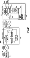
- Figure 12 is a block diagram of the voice coding-and-transmission system of the ninth embodiment of the present invention.
- This embodiment is obtained by further applying the same improvement as that shown in the embodiment 3 to the relay node of the embodiment 7. That is, a relay decoder, relay encoder, and voice detector use the parameter separator 108C, encoder 114C, and voice detector 110C having the same respective functions as in embodiment 3.
- the parameter separator 108C fetches only some of the adaptive parameters included in a voice signal and generates, instead of a complete voice signal, a voice code in accordance with the fetched adaptive parameters. This improvement further decreases the processing load and hardware scale of the relay node.
- the embodiments 1 to 9 basically perform synchronous resetting between a relay encoder of a relay node and a reception decoder of a reception node at start of voicing.
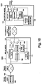
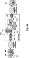
- Figure 13 is a block diagram of the voice coding-and-transmission system of the tenth embodiment of the present invention.
- This embodiment does not perform the above synchronous resetting between a relay encoder and a reception decoder at start of voicing, but most components of this embodiment are common to those of the embodiments 1 to 9. Therefore, in Fig. 13 as well, in order to simply the description, a component having the same function as that described for the embodiment 1 is provided with the same symbol as in Fig. 1.
- a relay node 204 has an abnormal-sound suppression code generator 206 instead of a relay encoder such as the encoder 114.
- the abnormal-sound suppression code generator 206 is also a form of encoder. However, the generator 206 is different from the encoder 114 in that it generates a voice code for suppressing abnormal sound when the abnormal sound may be produced. Because this embodiment does not perform synchronous resetting as described above, neither the relay node 204 nor the reception node 202 require any means for determining a reference value for differential coding/decoding at start of voicing, that is, the memories 118 and 128 of the embodiment 1, the pseudo background noise generators 140 and 144 of the embodiment 4, or the task controllers 160 and 162 of the embodiment 7.
- the decoder 108 once decodes a voice code sent from the transmission node 100 as a voice signal.
- the voice detector 110 detects the presence or absence of a talk spurt in accordance with the voice signal and decides an operation mode of the relay node according to a detection result.
- the coding/decoding system of the present invention has three operation modes. Description of these operation modes is omitted because the operation modes are the same as those described for the embodiment 1.
- the operation in mode 3 (voice state) is completely identical to that in mode 3 shown in the embodiment 1.
- the voice detector 110 detects the change of operation modes from 3 to 1, it sends a control signal to the silent period eliminator 112.
- a changeover switch in the silent period eliminator 112 corresponds to the control signal to be switched to the terminal-112b side and the output of a voice code from the relay node 204 stops.
- the voice detector 110 is continuously operated because it is necessary to monitor the change of operation modes.
- the abnormal-sound suppression code generator 206 does not to be operated.
- the voice/silence information extractor 120 fetches mode information from a silent-period-vanished voice code transmitted from the transmission line A and outputs a control signal according to the change of operation modes from 3 to 1 to the changeover switch 126.
- the changeover switch 126 is switched to the terminal-126a side in accordance with the control signal, a pseudo background noise of the pseudo background noise generator 124 is output from the reception node 202, and a natural silent state is transferred to a receiver.
- the voice detector 110 When the voice detector 110 detects the change of operation modes from 1 to 2, it sends the silent period eliminator 112 a control signal for notifying of the change from a silent state to a voiceful state.
- a changeover switch in the silent period eliminator 112 responds to the control signal to be switched to the terminal-112c side.
- the abnormal-sound suppression code generator 206 starts operation in accordance with the control signal.
- the abnormal-sound suppression code generator 206 serves as a unit for outputting a corrected voice code obtained by correcting a high-efficiency voice code output from the encoder 106.
- the corrected voice code is an optimized voice code which causes little abnormal sound, even if it is input to a decoder 122 having a different internal state.
- the internal state of the encoder 106 coincides with that of the decoder 122, no abnormal sound is produced even if any voice signal is input to the encoder because the stability of the coding/decoding system is assured.
- the probability is very high that the coding/decoding system is an unstable system.
- the unstable system causes sudden divergence of the gain value and produces abnormal sound such as "gya" or "bu” (phonetic).
- One of the methods for preventing such abnormal sound is to moderate the divergence rate by attenuating the gain value of a voice signal input to the unstable coding/decoding system.
- One of the methods for attenuating the gain value of a voice signal is a method of noticing the value of a gain codebook.
- the abnormal-sound suppression code generator 206 always monitors the power of a voice signal input to the encoder 106 by using a voice signal decoded by the decoder 108 of the relay node 204. When the generator 206 detects the input of a high-gain voice signal, it limits the value of a gain code.
- the abnormal-sound suppression code generator 206 selects a gain code having the threshold value or more, it forcibly replaces the gain code with a gain code having the threshold value or less in the period of mode 2.
- the replaced gain code is returned to the encoder 106 and used for the adaptive operation of a local decoder.
- the voice/silence information extractor 120 fetches mode information from a silent-period-vanished voice code transmitted through the transmission line A and outputs a control signal according to the change of operation modes from 1 to 2 to the changeover switch 126.
- the changeover switch 126 is switched to the terminal-126b side in accordance with the control signal. High-efficiency-coded data input to the decoder 122 does not require special processing because it is already abnormal-sound-suppressed.
- the voice detector 110 decides mode 3, it switches a changeover switch in the silent period eliminator 112 to the terminal-112a side and directly outputs a high-efficiency voice code sent from the encoder 106 of the transmission node 100 to the transmission line A. Operations of the reception node 202 are the same as those in mode 2.
- the present voice coding-and-transmission system avoids abnormal sound by suppressing gain in the transient period immediately after start of voicing which may cause abnormal sound, the biggest factor of voice quality degradation. Because the system is realized only by adding simple circuits such as a power monitor and a limiter, it is possible to decrease the processor processing load and hardware scale compared to the other embodiments above. Moreover, because operations are performed in a short transient period immediately after start of voicing and an output of the encoder 106 is directly transmitted in a voice period (mode 3) after the transient period, it is possible to avoid quality degradation and fully realize the performance of a high-efficiency voice coding system.
- Figure 14 is a block diagram of a relay node for explaining the eleventh embodiment of the present invention. This embodiment is obtained by applying the improvement similar to that shown in the embodiment 3 to the relay node of the embodiment 10.
- the transmission node 100 and the reception node 202 are not illustrated because they are the same as those described for the embodiment 10 and only the relay node is shown.
- a component having the same function as that described for the embodiment 10 is provided with the same symbol as in Fig. 10 and its description is not repeated.
- the character B is added to the symbol in Fig. 10 so that the corresponds once with the components of the embodiment 10 can easily be understood.
- This embodiment is different from the embodiment 10 in that a relay decoder and a voice detector use the parameter separator 108C and the voice detector 110C having the same respective functions as in embodiment 3 and an abnormal-sound suppression code generator 206B corresponding to the separator 108C and the detector 110C.
- the parameter separator 108C fetches only some of the adaptive parameters included in a voice signal and outputs them to the abnormal-sound suppression code generator 206B.
- the fetched adaptive parameters include gain codes.
- the abnormal-sound suppression code generator 206B generates a voice code instead of a complete voice signal in accordance with the fetched voice parameters.
- the parameter separator 108C outputs, for example, pitch information (or excitation signal information) to the voice detector 110C.
- the voice detector 110C detects voice in accordance with the pitch information (or the excitation signal information). This improvement further decreases the processing load and hardware scale of the relay node.
- Figure 15 is a block diagram of the voice coding-and-transmission system of the twelfth embodiment of the present invention. Many components of this embodiment are common to those of the embodiment 1. Therefore, in Fig. 15, a component having the same function as that described for the embodiment 1 is provided with the same symbol as in Fig. 1.
- This embodiment is a system using an abnormal-sound suppression code generator the same as the embodiment 10 does.
- this embodiment has an abnormal-sound suppression code generator 306 having the same function as the abnormal-sound suppression code generator 206 of the embodiment 10 at the reception node 302 side.
- a relay node 304 operates in the same way in both mode 2 and mode 3. That is, a voice detector 308 of the relay node 304 generates a control signal corresponding to a voice period or a silent period in accordance with a voice signal decoded by the decoder 108.
- a silent period eliminator 310 has a built-in changeover switch having two switching terminals corresponding to the voice period or silent period.
- a voice/silence information extractor 312 of the reception node 302 outputs control signals corresponding to three operation modes.
- a changeover switch 314 connects the abnormal-sound suppression code generator 306 or transmission line A to the decoder 122 in accordance with the control signals.
- a change over switch of the silent period eliminator 310 is connected to the terminal-310b side but there are no connections to the transmission line A. That is, silent-period-eliminating is performed.
- the changeover switch 126 is connected to the terminal-126a side and a pseudo background noise is output to a receiver.
- a changeover switch in the silent period eliminator 310 is connected to the terminal-310a side in accordance with a control signal from the voice detector 308 and a high-efficiency voice code is directly transmitted to the transmission line A from the transmission node 100.
- mode 2 and mode 3 are not distinguished in the relay node 304, they are distinguished in the reception node 302. This point is opposite from the case of the embodiment 10.
- the changeover switch 314 is switched to the terminal-314a side in accordance with a control signal from the voice/silence information extractor 312 and the changeover switch 126 is switched to the terminal-126b side.
- the abnormal-sound suppression code generator 306 converts a silent-period-vanished voice code to a corrected voice code in which similar gain adaptation of the voice code is performed as in the case of the embodiment 10 and the decoder 122 decodes the corrected voice code to generate a voice signal and output it to a receiver.
- Abnormal sound is suppressed because gain adaptation of the voice code is performed and it is possible to prevent abnormal sound, even if the present operation mode thereafter changes to operation mode 3, because shifting between the internal states of the encoder 106 and decoder 122 of the transmission node is performed gradually.
- the changeover switch 314 is switched to the terminal-314b side in accordance with a control signal from the voice/silence information extractor 312 and the decoder 122 receives a high-efficiency voice code generated by the transmission node 100 from the transmission line A.
- Figure 16 is a block diagram of the voice coding-and-transmission system of the thirteenth embodiment of the present invention.
- a component having the same function as that described for the embodiment 1 is provided with the same symbol as in Fig. 1.
- This embodiment uses the high-efficiency voice coding system according to ITU Recommendation G.728.
- a high-efficiency coding system applicable to the present invention is not restricted to the above voice coding system.
- a relay node 404 coding/decoding related to gain is performed by using a gain codebook.
- the gain codebook makes one gain correspond to every several ranges provided for the gain value of a voice signal as a quantized value.
- a gain code is made to correspond to the quantized value.
- standard gain codebooks 408 and 410 are the same normally used codebooks. Specifically, he standard gain codebooks 408 and 410 are memories storing gain codebooks specified by ITU Recommendation G.728.
- Suppressed gain codebooks 412 and 414 are memories storing gain codebooks having only quantized gain values causing no divergence, even for an unstable coding/decoding system, by attenuating the quantized values of he standard gain codebooks 408 and 414. That is, a suppressed gain codebook and a standard gain codebook have the same range section (gain value range) for gain values. In the same range, for example, the quantized gain value of the suppressed gain codebook is given a value further attenuated than that of the standard gain codebook, that is, a smaller value. An attenuation degree is set to a larger value for a gain value range at a higher position.
- a suppressed gain codebook having a gain value range different from that of a standard gain codebook It is also possible to used a suppressed gain codebook having a gain value range different from that of a standard gain codebook. For example, it is possible that the lower limit of the highest gain value range of a suppressed gain codebook is smaller than that of a standard gain value codebook. In this case, it is possible to set the quantized gain value corresponding to the highest gain value range of the suppressed gain codebook to a quantized gain value attenuation degree higher than the above case of having the same gain value range and thereby, obtain a suppressed gain codebook having a high abnormal-sound suppression effect, as will be mentioned later.
- a decoder 416 performs decoding by using the standard gain codebook 408, an encoder 418 performs coding by using the suppressed gain codebook 412, and a decoder 420 performs decoding by switching the standard gain codebook 410 and the suppressed gain codebook 414.
- Gain codebooks to be connected to the decoder 420 are switched by a changeover switch 422.
- the changeover switch 422 is switched by a control signal sent from a voice/silence information extractor 424.
- the coding/decoding system of the present system has three operation modes described for the embodiment 1.
- the voice/silence information extractor 424 outputs control signals corresponding to these three operation modes in the same way as the voice/silence information extractor 312 of the embodiment 12.
- the decoder 416 once decodes a high-efficiency voice code sent from the transmission node 100 as a voice signal and the voice detector 110 detects presence or absence of a talk spurt in accordance with the voice signal to decide an operation mode of the relay node 404 in accordance with a detection result.
- the operation in mode 3 (voice state) is completely identical to that in mode 3 shown in the embodiment 1.
- the voice detector 110 in the relay node 404 detects the change of operation modes from 3 to 1, it sends a control signal to the silent period eliminator 112.
- a changeover switch in the silent period eliminator 112 is switched to the terminal-112b side by responding to the control signal but no data is output to the transmission line A. That is, the line A is silent-period-vanished. It is permitted that the encoder 418 is in an indefinite state.
- the voice/silence information extractor 424 fetches mode information from a silent-period-vanished voice code transmitted from the transmission line A, extracts the information for notifying the change of operation modes from 3 to 1, and sends a control signal reflecting the information to the changeover switch 126.
- the changeover switch 126 is switched to the terminal-126a side in accordance with the control signal and a pseudo-background noise is output to a receiver. In this case, it is permitted that the decoder 420 is in an indefinite state.
- the voice detector 110 detects the change of operation modes from 1 to 2, it generates a control signal and a changeover switch in the silent period eliminator 112 is switched to the terminal-112c side in accordance with the control signal.
- a high-efficiency voice code output from the encoder 418 is output to the transmission line A from the relay node 404 and transmitted to the reception node 402.
- the voice/silence information extractor 424 detects the change of operation modes from 1 to 2 and generates a control signal.
- the changeover switch 126 is switched to the terminal-126b side.
- the changeover switch 422 is switched to the terminal 422b to connect the decoder 420 with the suppressed gain codebook 414.
- the decoder 420 decodes a silent-period-vanished voice code sent from the transmission line A by using the suppressed gain codebook 414 and outputs a voice signal to a receiver.
- the internal state of the decoder 420 of the reception node 402 is different from the internal state of the encoder 418 of the relay node 404.
- abnormal sound can be avoided because the selected suppressed-gain codebook 414 is optimized so that no divergence occurs, even in an unstable coding/decoding system.
- a voice signal output from the decoder 420 is not very faithful to the original voice signal input to the encoder 106 because the encoder 418 and decoder 420 are different in internal state. That is, the S/N ratio tends to get lower than the normal S/N ratio.
- a voice signal coded/decoded in mode 2 is in many cases a consonant part at the head of a talk spurt. If the voice waveform of a consonant part is very noisy, the acoustic property of an original voice signal is not lost, even for a low S/N ratio. Therefore, even in the case of the simple structure shown in Fig. 16, no abnormal sound is produced and it is possible to reproduce voices with a relatively small degradation of voice quality.
- the present voice coding-and-transmission system uses a method of changing coding tables used for a transient period, so that a voice code causing divergence of the system is not output instead of using a method of readapting a voice code output, from the encoder 106.
- This embodiment has an advantage preferable for practical use that the embodiment can easily be executed because the embodiment requires a fewer control signals be added and has few units for performing complex processing as compared to the above embodiments.
- Figure 17 is a block diagram of the voice coding-and-transmission system of the fourteenth embodiment of the present invention. This embodiment is obtained by applying the same improvement as that shown in the embodiment 2 to the relay node of the embodiment 13. In Fig. 17, a component having the same function as that described for the embodiment 13 is provided with the same symbol as in Fig. 16.
- a decoder 416B decodes a voice signal and outputs some of the adaptive parameters.
- An adaptive parameter is generated in high-efficiency coding such as ADPCM and serves as a voice parameter for constituting a voice signal.
- An encoder 418B receives the voice signal and adaptive parameters. In the case of the encoder 418B, it is possible to omit the processing for generating adaptive parameters input.
- Figure 18 is a block diagram of the voice coding-and-transmission system of the fifteenth embodiment of the present invention. This embodiment is obtained by applying the same improvement as that shown in the embodiment 3 to the relay node of the embodiment 13. In Fig. 18, a component having the same function as that described for the embodiment 13 is provided with the same symbol as in Fig. 16.
- a parameter separator 416C is constituted by omitting some processing from the decoder 416B in Fig. 17.
- the parameter separator 416C is not provided with a function for decoding a voice signal in the complete form and is only provided with a parameter extracting function.
- the parameter separator 416C outputs an excitation signal and an coding parameter to the encoder 418C and excitation signal information to a voice detector 440.
- the voice detector 440 detects voice in accordance with the excitation signal information.
- Other operations of this voice coding-and- transmission system are the same as those of the embodiment 13. This improvement further decreases the processing load and hardware scale of the relay node.
- Figure 19 is a block diagram of the voice coding-and-transmission system of the sixteenth embodiment of the present invention.
- a component having the same function as that described for the embodiment 1 is provided with the same symbol as in Fig. 1.
- This embodiment is described below by referring to Fig. 19.
- This embodiment uses a quantizer 506 as a relay encoder and a reception node 502 is provided with an inverse quantizer 508 correspondingly to the quantizer 506.
- An internal state adapting section 510 codes a voice signal sent from the inverse quantizer 508 by the differential coding system used for the encoder 106 and outputs the coded voice signal to the decoder 122.
- the internal state adapting section 510 has functions for reflecting the processing in the inverse quantizer 508 on the internal state of the decoder 122 and adapting the reference value for the differential coding in the decoder 122 to that of the encoder 106 of the transmission node 100.
- the coding/decoding system of the present system has three operation modes as described for the embodiment 1.
- the voice detector 110 discriminates between these operation modes in a relay node 504.
- a voice/silence information extractor 512 discriminates between the silent-period-eliminated voice code sent from the relay node 504 and outputs a control signal corresponding to each operation mode.
- Changeover switches 514 and 516 are switched in accordance with a control signal sent from the voice/silence information extractor 512. Operations of this embodiment are described below by referring to Fig. 19.
- the decoder 108 once decodes a voice code sent from the transmission node 100 as a voice signal.
- the voice detector 110 detects presence or absence of a talk spurt in accordance with the voice signal and decides an operation mode of the relay node in accordance with the detection result.
- the coding/decoding system of the present invention has three operation modes. However, description of these operation mode is omitted because they are the same as those described for the embodiment 1.
- mode 3 Voiceful state
- mode 1 Operations of mode 3 (voiceful state) and mode 1 are the same as those of modes 3 and 1 shown in the embodiment 1 except that the changeover switch 514 is connected to the terminal-514a side.
- the changeover switch 516 is switched to a terminal 516a in mode 1 to use an output sent from the pseudo background noise generator 124 as an output of the reception node 502 and, moreover, it is switched to a terminal 516b in mode 3 to use a voice signal sent from the decoder 122 as an output of the reception node 502.
- the voice detector 110 detects the change of operation modes from 1 to 2 and sends a control signal to the silent period eliminator 112.
- a changeover switch in the silent period eliminator 112 is switched to the terminal-112c side.
- the quantizer 506 re-quantizes a voice signal decoded by the decoder 108 for every sample and outputs the re-quantized voice signal.
- the re-quantized voice signal is substituted for a voice code.
- the re-quantized voice signal is output to the transmission line A from the relay node 504.
- the voice/silence information extractor 512 fetches mode information from a voice code (quantized voice signal) transmitted from the transmission line A and outputs a control signal according to the change of operation modes from 1 to 2 to the changeover switch 516.
- the changeover switch 516 is connected to a terminal 516c and the changeover switch 514 is connected to a terminal 514b.
- the inverse quantizer 508 inversely quantizes the voice code transmitted from the transmission line A to generate a voice signal and outputs the voice signal to a receiver via the changeover switch 516.
- the processings performed by the quantizer 506 and the inverse quantizer 508 are not based on a difference, an operation such as synchronous resetting is unnecessary in mode 2.
- an operation such as synchronous resetting is unnecessary in mode 2.
- the internal state adapting section 510 is the means for the above purpose.
- the inversely-quantized voice signal is also supplied to the internal state adapting section 510 which supplies a calculated adaptive parameter to the decoder 122 to perform the operation for adapting the internal state of the decoder 122.
- the quantizer 506 it is necessary for the quantizer 506 to perform quantization at the number of quantization steps adapted to the transmission line A and the high-efficiency coding system used for the present system.
- the coding system currently used is the system according to ITU Recommendation G.728 (transmission rate of 16 kbit/s) and the transmission rate per channel of the transmission line A is constant, 2 bits are assigned to each sample as the number of quantization bits.
- an input signal in mode 2 mainly has a consonant part. Because the voice waveform of a consonant part is a noisy signal, it is almost the same as the acoustic characteristic of a quantized noise and the period of mode 2 is very short, i.e. hundreds of milliseconds at most. Therefore, acoustic deterioration is relatively small. Because the dynamic range of voice signals input during the above period is relatively small, it is possible to completely express the value of the signal even if the number of quantization steps is small.
- the transmission line A can handle a variable-speed transmission signal
- Figure 20 is a block diagram showing a structure of the internal state adapting section 510.
- This is an example of the internal state adapting section 510 when ITU Recommendation G.728 is used for a high-efficiency voice coding system.
- This example has the forward structure shown in Fig. 20 in order to perform adaptation by using a voice signal as an input.
- the structure is opposite to that of the decoder shown in Fig. 28.
- mode 1 changes to mode 2
- the internal state of the encoder 106 of the transmission node 100 no longer coincides with that of the decoder 122 of the reception node 502.
- the adaptive operation of the decoder 122 is continued in accordance with a voice signal in mode 2
- the internal state of the encoder 106 of the transmission node 100 approaches that of the decoder 122 of the reception node 502 as explained in the embodiment 1. Therefore, no abnormal sound is produced, even if operation modes thereafter change from 2 to 3.
- Figure 21 is a block diagram of the voice coding-and-transmission system of the seventeenth embodiment of the present invention. Because this embodiment is obtained by improving the embodiment 16, both embodiments use many common components. Therefore, in Fig. 21, a component having the same function as that described for the embodiment 16 is provided with the same symbol as in Fig. 16.
- This embodiment uses a relatively simple second high-efficiency coding/decoding system instead of the quantizer/inverse quantizer used for the embodiment 16. That is, the encoder 520 and the decoder 522 use an coding/decoding system not based on differential processing so as to disuse the operation such as synchronous resetting in mode 2 and performs the adaptive operation of the decoder 122 by using the internal state adapting section 510 so that operation in mode 3 can be performed. By this improvement, a preferable voice quality can be obtained compared to the case of the embodiment 17, though the processing load slightly increases.
- Figure 22 is a block diagram of the voice coding-and-transmission system of the eighteenth embodiment of the present invention.
- This embodiment and the embodiment 1 use many common components. Therefore, in Fig. 22, a component having the same function as that described for the embodiment 1 is provided with the same symbol as in Fig. 1 and its description is omitted.
- a buffer 606 is provided in a route for relaying a voice code to the transmission line A from the transmission line B. Though operations of this embodiment are described later, the tandem connection for the embodiment 1 or synchronous resetting between an encoder used for the tandem connection and a decoder of a reception node is not performed.
- this voice coding-and-transmission system is not provided with a relay encoder, means for determining an coding reference value, or means for determining a decoding reference value.
- a voice detector 608 of a relay node 604 generates a control signal corresponding to a voice period or silent period in accordance with a voice signal decoded by the decoder 108.
- a silent period eliminator 610 has a built-in changeover switch having two switching terminals corresponding to the voice period or silent period.
- FIG. 23 is a waveform diagram of a voice signal output from the decoder 108.
- Y axis represents signal level and x axis represents time.
- the voice detector 608 divides the voice signal into three periods (sections) and operates the relay node 604 in a different operation mode corresponding to each period.
- Mode 1' corresponds to a period excluding ten msec among periods at the tail in which no talk spurt is detected.
- Mode 2' corresponds to a period of tens of milliseconds (referred to as a hangover period) excluded from the tail of the period of mode 1'.
- mode 3' corresponds to a period in which a talk spurt is detected.
- the period corresponding to mode 1' is referred to as a silent period and the periods corresponding to modes 2' and 3' are referred to as a voice period.
- Operations of the embodiment 18 are described by referring to Fig. 22.
- the present system accumulates high-efficiency voice codes input to the relay node 604 in the buffer 606 which is a FIFO buffer in order to delay them.
- a time difference equivalent to the buffer length occurs between the transmission lines B and A. That is, detection of a talk spurt by the voice detector 608 preceded by a time equivalent to the buffer length in accordance with a voice code and thereby, the change point from mode 1' to mode 2' can be obtained.
- the present system is essentially different from the prior art at the point that the buffer 606 is set to the relay node 604 to generate a delay separately from the delay by the processing delay unit 116 so that the change from a silent period to a voice period can be detected in advance.
- the voice detector 608 detects "presence" of a talk spurt, it switches a changeover switch in the silent period eliminator 610 to the terminal-610 a side and transmits a voice code sent from the transmission node 100 to the transmission line A.
- the voice code is delayed by the buffer 606 and a silent overhang period is included in the head of a silent-period-eliminated voice code to be transmitted to the transmission line A.
- the voice detector 608 detects "absence" of a talk spurt, it switches a changeover switch in the silent period eliminator 610 to the terminal-610b side but it does not transmit any data to the transmission line A.
- a control signal sent from the voice detector 608 at the end of voicing is delayed longer than the hangover period. Thereby, it is possible to prevent the tail of the voice code delayed by the buffer 606 from pausing.
- the voice/silence information extractor 120 outputs a control signal corresponding to presence or absence of a talk spurt to the changeover switch 126 the same as the voice detector 608 does.
- the changeover switch 126 is switched to the decoder-122 side in a voiceful period and to the pseudo-background-noise-generator-124 side in a silent period.
- abnormal sound is produced due to divergence of a system when the following two conditions occur at the same time.
- the duration of mode 2' be approximately tens to hundreds of milliseconds, in which time the difference between the internal states of the encoder 106 and the decoder 122 completely converges.
- the duration is over-lengthened, it is necessary to set a duration most suitable for a system to which mode 2' is applied by adequately considering the even balance between the duration and factors.
- Figure 24 is a block diagram of the voice coding-and-transmission system of the nineteenth embodiment of the present invention. This embodiment is obtained by improving the reception node of the embodiment 18. Therefore, in Fig. 24, a component having the same function as that described for the embodiment 18 is provided with the same symbol as in Fig. 22 and its description is omitted.
- the present system is constituted so as to output pseudo background noises continuously after mode 1' by setting a timer 620 for counting delay time of the buffer 606 to a reception node 602B and connecting the changeover switch 126 to the terminal-126a side in mode 2' (hangover period).
- the possibility of occurrence of abnormal sound is low in mode 2', the possibility is completely eliminated in mode 2' by using the structure of the present system.
- FIG. 25 is a block diagram of the voice coding-and-transmission system of the twentieth embodiment of the present invention.
- This embodiment is another embodiment obtained by improving the reception node of the embodiment 18. Therefore, in Fig. 25, a component having the same function as that described for the embodiment 18 is provided with the same symbol as in Fig. 22 and its description is omitted.
- a reception node 602C of the present system is provided with the timer 620 for counting the delay time of the buffer 606, as in embodiment 19, a voice muting circuit 640, and is constituted so as to output a muted voice signal by driving the voice muting circuit 640 while the timer 620 is in mode 2' (hangover period).
- mode 2' (hangover period).
- Figure 26 is a block diagram of the voice coding-and-transmission system of the twenty-first embodiment of the present invention. This embodiment is obtained by improving the embodiment 19. Therefore, in Fig. 26, a component having the same function as that described for the embodiment 19 is provided with the same symbol as in Fig. 24 and its description is omitted.
- the embodiment 21 is characterized in that a relay node 604D is provided with an internal state encoder (reference state encoder) 660 having a function of referring to internal parameters of the decoder 108 and coding them and a reception node 602D is provided with an internal state decoder (reference state decoder) having a function of decoding internal parameters coded by the internal state encoder 660 and setting the values of the parameters to a proper memory area of the decoder 122.
- an internal state encoder reference state encoder
- reference state decoder reference state decoder
- the relay node 604D connects a changeover switch in a silent period eliminator 664 to a terminal 664C and transmits an output of the internal state encoder 660 to the transmission line A.
- the reception node 602D immediately decodes the coded signal and sets a parameter reflecting the internal state of the encoder 106 to the decoder 122.
- the present system directly transmits internal parameter information and forcibly makes the internal state of the encoder 106 coincide with that of the decoder 122.
- FIG. 27 is a block diagram of the voice coding-and-transmission system of this embodiment.
- a transmission node 700 divides an original voice code obtained by coding a voice signal into cells and outputs these cells to a transmission line A.
- the transmission line A is an ATM transmission network.
- a transmission line B in which a reception node 702 is connected is an STM transmission network.
- a relay node 704 is an ATM-STM relay node for connecting these two transmission networks, receives a cell transferred in a asynchronous transfer mode from the transmission node 700, extracts the original voice code and outputs the voice code to the transmission line B in a synchronous mode.
- the reception node 702 decodes the voice code transferred in the synchronous mode and outputs a voice signal.
- the transmission node 700 has an encoder (coding unit) 706 for digitizing the voice signal inputted and for coding with high compression rate. Any coding method may be applied to the embodiment of the present invention.
- the voice code outputted from the transmission node 700 may be the high efficiency voice code applied the differential-coding described in the above embodiment, or be a voice code applied the silent-period-elimination.
- a cell composer 708 divides a sequential original voice code generated in the encoder 706, and assorts the original voice code into the cell. Namely, each cell includes a fragment of the original voice code.
- the voice signal is transmitted through the transmission line A which is the ATM network in a burst mode per cell unit.
- the cell is transmitted from the transmission node 700 to the relay node 704 through the transmission line A. Fluctuation in a reached timing induced by a different transmission path though which the cell passes is absorbed in a FIFO buffer 710. A cell decomposing portion 712 decomposes the cell received and generates the sequential original voice code.
- An vanished cell detector 714 is a relay control means of detecting a dead cell (vanished cell) due to a disuse or a delay in the ATM network, and of generating a control signal (relay control signal) for controlling operations of each portion in the relay node 704.
- the original voice code is branched into two parts.
- One part is inputted to a decoder (relay decoder) 716.
- the decoder 716 decodes the voice code extracted from the cell into an original digital sampling voice signal.
- a synchronous incoming unit 718 has a function of mating an operation timing between the decoder 706 and the decoder 716.
- a vanished cell compensator 720 compensates a voice signal for the vanished cell based on an output from the decoder 716.
- a memory 722 consists of a memory or the like and temporarily stores a latest voice signal used for compensating the vanished cell.
- An encoder (relay encoder) 724 performs the same coding as the encoder 706 does and generates a voice code (relay voice code).
- a delaying unit 726 is inputted to a delaying unit 726.
- a delay time belonging to the delaying unit 726 is equal to a delay time in a compensation processing of the vanished cell performed by the decoder 716, the vanished cell compensator 720 and the encoder 724.
- a selector switch 728 is controlled by the relay control signal and outputs either the original voice signal outputted from the delaying unit 726 or the relay voice code outputted from the encoder 724.
- the voice code outputted from the selector switch 728 is sent to the transmission line B which is the STM network through a synchronous incoming unit 730.
- a decoder 732 is the same as the decoder 716.
- the encoder 706 codes based on a high efficiency coding algorithm, and generates a voice code (original voice code).
- the original voice code is changed to a cell in the cell composer 708, and is sent asynchronously to the transmission line A in a burst mode.
- the relay node 704 receives the cell from the transmission line A.
- the cell in which fluctuation in a reached timing is absorbed by the buffer 710 is decomposed in the cell decomposing unit 712, and the original voice code is extracted therefrom.
- a coding timing of the original voice code mates with that of the encoder 706 at the reception node. So far this is the same as the conventional voice relay transmission system using a tandem method.
- the voice code retimed is branched into two parts as described above.
- One part is inputted to the decoder 716, and is decoded to a digitized voice signal, for example a PCM voice signal, based on an algorithm in accordance with the encoder 706.
- the voice signal decoded is stored in the memory 722 for a predetermined period.
- the vanished cell compensator 720 compensates the vanished cell based on the voice signal information stored in the memory 722 receiving the relay control signal from the vanished cell detector 714. Whenever the vanished cell is detected in the relay node, it is needed that the decoder 716 is operated continuously and the latest voice signal information is always inputted to the memory 722 so as to compensate the vanished cell.
- the voice signal is compensated for the vanished cell based on the information in the memory 722.
- a compensation method such as a linear interpolation / a repeat interpolation based on a pitch cycle / an extrapolation with a linear prediction / a mute has been devised.
- the compensation method is not limited.
- the voice signal compensated for the vanished cell information is inputted to the encoder 724, coded based on the same algorithm as that of the encoder 706 at the reception node, and then sent to the selector switch 728.
- the other original voice code outputted from the synchronous incoming unit 718 is inputted to the selector switch 728 through the delaying unit 726.
- Timings of the original voice code passing through the normal condition route and the voice code (relay voice code) passing through the abnormal condition route are mated by the delaying unit 726.
- the selector switch 728 selects and outputs either one of the above two inputs based on the relay control signal in accordance with a determination of the vanished cell detector 714. In other words, the switch is switched to a terminal 728a under the normal condition and the voice code received from the ATM network is sent to the STM network side as it is. On the other hand, the switch is switched to a terminal 728b under the abnormal condition and the voice code compensated the vanished cell by the vanished cell compensator 720 is sent to the STM network side.
- the voice code outputted from the selector switch 728 is mated with an inherent timing of the transmission line B (STM network) in the synchronous incoming portion 730 and is then outputted to the transmission line B.
- STM network transmission line B
- major features of the present embodiment are in that a relay based on a digital-one-link connection which produces no accumulation of quantization errors is performed under the normal condition, and the vanished cell is compensated making a relay mode as a tandem connection under the abnormal condition.
- the high efficiency voice code transmitted through the transmission line B is decoded to the voice signal in the decoder 732 at the reception node 702. At this time, an impact of the cell disuse generated in the transmission line A is removed in the relay node 704, therefore, an excellent voice signal prevented a degradation can be decoded without conducting any special processing in the reception node 702.
- Figure 28 is a block diagram of the voice coding-and-transmission system of this embodiment.
- the present embodiment is obtained by improving the embodiment 22. With the improvement, a processor load caused by a coding processing, a decoding processing, an vanished cell compensation processing or the like in the relay node and a hardware size can be reduced.
- components having corresponding function to a component described for embodiment 22 are provided with the same symbol as in Fig. 27 and their description is not repeated.
- the character B is added to its symbol in Fig. 27 so that how the component corresponds to the component of the embodiment 22 can be easily understood.
- the decoder 716B conducts a part of the decoding processing of the decoder 716.
- the decoder 716B does not generate a complete voice signal, instead thereof, analyzes the voice signal and extracts a voice parameter which is one portion of the voice information included in the voice signal.
- the encoder 724B has a function of converting the voice parameter extracted in the decoder 716B into the high efficiency voice signal again.
- the vanished cell compensator 720B operates with receiving the relay control signal and compensates the voice parameter of the voice signal included in the vanished cell.
- a bit sequence including retimed voice code information is inputted to the decoder 716B.
- the decoder 716B analyze the bit sequence inputted and only extracts the voice parameter coded.
- the parameter extracting operation will be described using an existing voice coding algorithm.
- a case that an ITU Recommendation G.728 coding method (CS-ACELP method) is used as the high efficiency coding method will be described based on Figs. 29 and 30.
- Figure 29 is a block diagram of the encoder based on the ITU Recommendation G.728 method
- Figure 30 is a block diagram of the decoder according to the method.
- Detail algorithm of the CS-ACELP method is described in ITU-T Recommendation G.729, "Coding of Speech at 8 kbit/s Using Conjugate-structure Algebraic-Code-Excited Linear-Prediction (CS-ACELP)."
- the encoder 706 analyzs the voice signal inputted and extracts a parameter which characterizes the voice signal.
- the ITU Recommendation G.729 extracts LSP (line spectrum pair) information corresponding to a synthesis filter coefficient, an adaptive code book index and a fixed code book index corresponding to a waveform of an excitation sound source, adaptive code book gain information and fixed code book gain information corresponding to power of the excitation sound source.
- the excitation sound source expresses vocal vibration information
- the LSP information expresses tone mechanism information corresponding to a throat or a palato comparing to a human vocalization.
- Each parameter is quantized based on a specific algorithm, is converted to a bit sequence, is multiplexed, and is then outputted from the encoder 706.
- the multiplexed bit sequence inputted to the decoder 716B is converted into each parameter regarding the voice information by a function including the multi separation / parameter decoder 740 shown in Fig. 30.
- Each parameter extracted in the decoder 716B is stored in the memory 722.
- the vanished cell compensator 720B operates receiving the relay control signal outputted from the vanished cell detector 714 when the cell vanishing is detected, in other words under the abnormal condition, and compensates the vanished cell based on the voice parameter stored in the memory 722.
- the decoder 716B is operated continuously so as to be capable of compensating the voice signal information included in the vanished cell. Namely, the voice parameter stored in the memory 722 is continuously updated. Moreover, the older the stored past parameter is, the less its validity for the compensation processing is.
- a stored parameter in the memory 722 is normally updated with a FIFO processing.
- a linear interpolation, a repeat interpolation, an extrapolation by a linear interpolation, an attenuation of a gain or the like has been devised as the compensation method.
- the compensation processing of the present invention is realized using these compensation methods and other compensation methods.
- the compensated parameter for the vanished cell information and represented a characteristic amount of the voice signal is inputted to the encoder 724B.
- the encoder 724B codes the parameter compensated by performing same processings as a parameter coding / multiplexor 742 in the encoder 706 at the reception node, and sends the voice code (relay voice code) to the selector switch 728.
- the voice code outputted from the synchronous incoming unit 718 is inputted to the selector switch 728 through the delaying unit 716.
- Timings of the voice code (original voice code) passing through the normal condition route and the voice code (relay voice code) passing through the abnormal condition route in other words a route including the decoder 716, the vanished cell compensator 720 and the encoder 724B are mated by the delaying unit 726.
- the selector switch 728 selects and outputs either one of the above two inputs based on the relay control signal outputted from the vanished cell detector 714. In other words, the switch is switched to a terminal 728a under the normal condition and the voice code received from the ATM network is sent to the STM network side as it is. On the other hand, for the abnormal conditions switch is switched to a terminal 728b and the voice code compensating for the vanished cell by the vanished cell compensator 720B is sent to the STM network side.
- the voice code outputted from the selector switch 728 is mated with an inherent timing of the transmission line B (STM network) in the synchronous incoming portion 730 and is then outputted to the transmission line B. Processings thereafter are identical to the embodiment 22.
- STM network transmission line B
- the decoder 716 in the relay node of the embodiment 22 needs to perform entire decoding processing of the decoder shown in Fig. 30, and the encoder 724 in the relay node needs to perform entire coding processing of the encoder shown in Fig. 29, respectively.
- any decoder 716B only performing a processing done by the multi separation / parameter decoder 740 among the decoding processings shown in Fig. 30 can be applied and any encoder 724B only performing a processing done by the parameter coding / multiplexor 742 among the coding processings shown in Fig. 29 can be applied.
- Figure 31 is a block diagram of the voice coding-and-transmission system of this embodiment.
- the present embodiment is obtained by further improving the embodiment 23.
- the vanished cell compensation processing using only the voice parameter which is a part of the voice signal information does not decode the voice entirely, and therefore exhibiting an effect such as relieving a processing load in embodiment 23.
- an abnormal sound may be generated caused by a mismatch of internal statuses between the relay node 704 and the reception node 702 under the coding processing or the decoding processing.
- An object of the relay node in the present embodiment is to prevent generating the abnormal sound in the regenerated voice at the reception node and to reduce a listener's discomfort by adding further functions to the relay node shown in Fig. 28.
- Fig. 31 components having corresponding functions to those of a component described for the above embodiment are provided with the same symbol as in Figs. 27 and 28 and their description is not repeated.
- the character C is added to its symbol in Figs. 27 and 28 so that correspondance of the component to the component of the above embodiment can be easily understood.
- a generated abnormal sound detector (abnormal sound sensor) 750 monitors a voice signal outputted from a decoder (inspection decoder) 752 and detects the abnormal sound.
- a high efficiency coding corrector (voice code rectifier) 754 corrects a generated voice code in the encoder 724B by receiving a notice of the abnormal sound detection from the generated abnormal sound detector 750.
- further processing not existing in embodiment 23 is applied to a voice code obtained through a recoding processing of the encoder 724B.
- the voice code is inputted to the decoder 752.
- the decoder 752 has the same functions as the decoder 716, which is used as the relay decoder at the relay node 704 in the embodiment 22. However, in the relay node 704C, the decoder 752 is used for processing the inspection of the voice code after compensating for the vanished cell and has a different usage from the decoder 716.
- a voice signal is decoded based on a predetermined decoding algorithm.
- the decoded voice signal is inputted to the generated abnormal sound detector 750.
- the generated abnormal sound detector 750 detects the abnormal sound or a discomfort sound based on the voice signal.
- the abnormal sound or the discomfort sound is a click sound such as "bu” or "gya” (phonetic) in the regenerated sound generated by a leading edge in which the voice signal gain rapidly rises for a short time.
- a phenomenon where loud volume is decoded suddenly by an oscillation of a synthesis filter or a gain adaptive filter build in the decoder can be induced.
- the generated abnormal sound detector 750 detects a specific alternation in the voice signal that does not exist in a normal voice, and produces an alert signal.
- other methods for detecting the abnormal sound and the discomfort sound may be applied thereto.
- the corrector 754 corrects the voice code compensated the vanished cell.
- the correction processing muting the voice signal by lowering a gain parameter in case of using the above-mentioned ITU Recommendation G.729 CS-ACELP method.
- Such correction processing can remarkably reduce a frequency of generating the abnormal sound and give no discomfort to the listener, which is suitable for a practical use, although high fidelity of the voice regeneration is somewhat sacrificed.
- Figure 32 is a block diagram of the voice coding-and-transmission system of this embodiment.
- the present embodiment is obtained by further improving the embodiment 22.
- a component having the same function as that of the component described for the above embodiment is provided with the same symbol and its description is not repeated.
- the character D is added to its symbol so that how the component corresponds to the component of the above embodiment can easily be understood.
- a decoder 760 incorporates a decoding processing function corresponding to a coding algorithm adapted in the encoder 706 at the reception node 700 and a compensating processing function for burst vanishing of the coding data represented by the cell vanishing, thereby optimizing processing.
- the decoder 760 has an vanished cell compensation function.
- the relay control signal showing a result of detecting the cell vanishing as an output from the vanished cell detector 714 is inputted to the decoder 760, the decoder 760 performs a normal decoding processing and an vanished cell compensation processing as well.
- a degraded voice signal can be decoded if cell vanishing has occurred.
- an ITU Recommendation G.727 Embedded ADPCM method, an ITU Recommendation G.728 Annex I method, or the like are cited.
- Detail algorithms thereof are described in ITU-T recommendation G.727, "5-, 4-, 3-, and 2 bits sample Embedded Adaptive Differential Pulse Code Modulation" and ITU-T Recommendation G.728 Annex I, " G.728 Decoder Modifications for Frame Erasure Concealment,” respectively. The latter will be described as an example.
- Figure 33 is a block diagram showing a processing system in the decoder 760 based on the ITU Recommendation G.728 Annex I algorithm.
- the system performs decoding based on a normal ITU Recommendation G. 728 LD-CELP algorithm under the normal condition.
- a vector extraction processing unit 770 extracts a waveform vector and a gain value index from the voice code inputted to the decoder 760 respectively, and retrieves and extracts an excitation signal vector from a vector code book 772 based on the index.
- a gain multiplier 774 multiply the extracted excitation signal vector by a gain value predicted adaptively in a gain adaptation unit 776. Thereafter, the excitation signal vector is provided to a synthesis filter 778.
- the synthesis filter 778 synthesizes a synthesis voice vector based on a coefficient determined adaptively in a linear prediction analyzer 780.
- the gain adaptation unit 776 and the linear prediction analyzer 780 perform a backward type adaptive processing by a procedure similar to the encoder, and determine a prediction gain and a synthesis filter coefficient, respectively.
- 144 sample nearest excitation signals outputted from the gain multiplier 774 are stored on the memory 784 against a processing of compensating the vanished cell information by extrapolating with an vanished cell compensator 782 when the cell is eliminated.
- the vanished cell compensator 782 extrapolates based on a past excitation signal stored on the memory 784.
- the extrapolation processing is performed adaptively using an analyzed result in a pitch analyzing portion 786.
- an excitation signal wave is to be a periodic pulse sound source, therefore a value of a long period prediction gain calculated in the pitch analyzing portion 786 is relatively large.
- the present system aims at the property.
- the vanished cell compensator 782 determines "voiceful" when the value of the long period prediction gain parameter exceeds a predetermined threshold value, extrapolates by repeating the excitation signal stored on the memory 784 using also the pitch cycle obtained through an analysis in the pitch analyzing portion 786, and compensates a blank period due to the cell vanishing.
- the excitation signal does not exhibit the periodicity that the voiceful portion does, and is to be a predominant random waveform.
- the present system aimed at a noise of the excitation signal and uses the excitation signal rearranged randomly stored on the memory 407 as an extrapolation signal.
- the relay control signal provided from the vanished cell detector 714 is used for controlling a selector switch 788 that a signal inputted to the synthesis filter 778 is switched to an excitation signal outputted from the gain multiplier 774 or to an excitation signal compensated by the vanished cell compensator 782.
- the selector switch 788 Under the normal condition, the selector switch 788 is switched so as to provide an unmodified output from the gain multiplier 774 to the synthesis filter 778.
- the selector switch 788 is switched so as to provide an output from the vanished cell compensator 782 with the synthesis filter 778.
- An output from the decoder 760 is sent immediately to the encoder 724 and is applied the coding processing. Operations thereafter is entirely same as that of the embodiment 22.
- a system applied the ITU Recommendation G. 728 Annex I is described as an example.
- the present invention is not limited to a case using the coding system.
- the present invention can be applied to a system using any voice coding system capable of compensating and decoding a lost transmission signal in a burst mode such as the cell vanishing.
- the parameter used for the vanished cell compensation is an internal parameter, which is not the voice code and the voice signal, generated in the course of the voice coding processing or the decoding processing.
- an interpolation method or an extrapolation method can be changed adaptively according to a voice status (voiceful or silent), thereby enabling high quality vanished cell compensation.
- Figure 34 is a block diagram of the voice coding-and-transmission system of this embodiment.
- a correction function for suppressing an abnormal sound is added to the relay node described in the embodiment 25.
- Fig. 34 components having similar functions to components described in the above embodiment are provided with the same symbol and their description is not repeated.
- the character E is added to its symbol so that how the component corresponds to the component of the above embodiment can easily be understood.
- the generated abnormal sound detector 750 receives a voice signal from the decoder 760, and detects the abnormal sound in the voice signal.
- a voice signal corrector (voice signal rectifier) 800 receives the abnormal sound detection from the generated abnormal sound detector 750, and corrects the voice signal from the decoder 760.
- the present embodiment differs from embodiment 25 in that the voice signal is corrected using the generated abnormal sound detector 750 and the voice signal corrector 800 between the decoder 760 having the vanished cell compensation function and the decoder 724.
- the generated abnormal sound detector 750 produces an alert signal when detecting the abnormal sound and the discomfort sound in the voice signal inputted from the decoder 760.
- the voice signal corrector 800 receives the alert signal, the corrector 800 corrects the voice code through means such as gain suppression.
- Such correction processing can remarkably reduce abnormal sound generation, while causing no discomfort to the listener, thereby making this approach suitable for practical use, although high fidelity of the voice regeneration is somewhat sacrificed.
- Figure 35 is a block diagram of the voice coding-and-transmission system of this embodiment.
- the present embodiment is obtained by further improving the embodiment 25.
- a component having the same function as that of the component described for the above embodiment is provided with the same symbol and its description is not repeated.
- the character F is added to its symbol so that how the component corresponds to the component of the above embodiment can easily be understood.
- a hangover adding unit (control signal delaying unit) 810 is a delaying unit for delaying the relay control signal outputted from the vanished cell detector 714, and is provided for delaying a signal of controlling an operation that the selector switch 728 is switched to the terminal 728a, in other words, to the digital one link connection.
- the timing that the selector switch 728 is switched from the terminal 728b to the terminal 728a is delayed to a return timing from "the abnormal condition (cell vanishing)" to "the normal condition (cell reception)" of determination in the vanished cell detector 714 by the hangover adding unit 810.
- the selector switch 728 is switched from the terminal 728b to the terminal 728a, immediately after the determination in the vanished cell detector 714 is returned from "the abnormal condition" to "the normal condition.”
- the reason for delaying the return of the selector switch 728 to the digital one link connection mentioned above is described below.
- the decoder 760 and the encoder 724 compensate the coded voice information included in the vanished cell.
- completely restoring the eliminated voice code completely by a method such as extrapolation is impossible. Therefore, a mismatch occurs between internal statuses of the encoder 706 at the transmission node 700 and the decoder 732 at the reception node 702. In other words, immediately after the normal condition is restored after the time elapsed corresponding to the vanished cell, the internal statuses between the transmission node 700 and the reception node 702 may be mismatched.
- abnormal sound may be generated.
- a voice coding method using so called a backward adaptation represented by the coding method based on the ITU Recommendation G.728 that parameters such as an internal filter coefficient and a gain are adapted based on the past restored voice signal it is known that past occurrences of mismatch of sending and a reception internal statuses directly affect the voice signal being decoded at present.
- the selector switch 728 is switched immediately after the normal condition is restored, abnormal sound is thereby generated resulting in a low quality voice.
- the selector switch 728 is kept at the terminal 728b for a while after the normal condition is restored to continue the tandem connection.
- the internal statuses of the encoder 706 at the transmission node 700 and the decoder 732 at the reception node 702 are closed to each other.
- the relay voice code compensating for the vanished cell is closed to the original voice code receiving from the transmission node.
- a delay of switching timing to the digital one link as one feature of the present invention is explained by applying the relay node 704D of the embodiment 25 using the decoder 706 having the vanished cell compensation function.
- this feature can also be applied to other embodiments regarding other ATM-STM relay nodes, for example to the relay node 704 of the embodiment 22 and the relay node 704B of the embodiment 23 to exhibit similar abnormal sound suppression effect.
- Figure 36 is a block diagram of the voice coding-and-transmission system of this embodiment.
- the present embodiment is obtained by further improving the embodiment 25.
- components having the same function as those described for the above embodiment are provided with the same symbol and their description is not repeated.
- the character G is added to its symbol so that its correspondence to the component of the above embodiment can easily be understood.
- a decoder 760G has the vanished cell compensation function similar to the decoder 760.
- the decoder 706G is different from the decoder 760 in view of outputting not only the voice signal 762, but also the coded voice parameter 764.
- the encoder 724G codes the voice signal utilizing the voice parameter from the decoder 760G.
- Figure 37 is a block diagram showing one internal configuration of the decoder 760G and the encoder 724G included in the relay node 704G shown in Fig. 36.
- FIG. 37 shows one example of a block configuration of the decoder 760G and the encoder 724G.
- a voice relay system using the aforementioned ITU Recommendation G.728 as the coding system is cited as an example, which is described referring to Fig. 37.
- the decoder 760G and the encoder 724G perform the decoding processing and the coding processing respectively based on the same algorithm, therefore, the parameters used in both are basically common. In addition, values of these parameters are obtained by analyzing common voice signals. The values of both parameters are expected to be the same if quantization errors are ignored.
- a value of an excitation gain provided to the gain multiplier 774 in the decoder 760G and a value of an excitation gain provided to a gain multiplier 820 in the encoder 724G may, strictly speaking, slightly differ, being affected by the quantization errors. However, these values are adapted with the same excitation signal and therefore are closed to each other very precisely.
- a coefficient value of the synthesis filter 778 in the decoder 760G and a coefficient value of a synthesis filter 822 in the encoder 724 are adapted with a same voice signal and therefore are closed to each other.
- an adaptation operation of the parameter is executed at one side of either the decoder 760 or the encoder 724, and the rest of them processing is performed utilizing the resulting value.
- the adaptation processing is reduced.
- processing load and power consumption can be reduced.
- the decoder 760G includes the gain adaptation unit 776, the vector code book 772, and the linear prediction analyzer 780 shown in Fig. 39.
- the excitation signal vector stored on the vector code book 772 is shared in each vector extractor 770 of the decoder 760G and the encoder 724G.
- the gain value predicted adaptively by the gain adaptation unit 776 is not only used at the gain multiplier 774 of the decoder 760G, but also provided to the gain multiplier 820 of the encoder 724G.
- the coefficient determined in the linear prediction analyzer 780 is not only used at the synthesis filter 778 of the decoder 760G, but also provided to the synthesis filter 822 of the encoder 724G.
- the encoder 724G generates the high efficiency voice code using the parameter provided from the decoder 760G.
- Figure 38 is a block diagram of the voice coding-and-transmission system of this embodiment.
- the present embodiment is obtained by further improving the embodiment 28.
- An object of the present embodiment is to much lower the processing load at the relay node and to decrease the hardware size.
- a component having a corresponding function to one described in the above embodiment is provided with the same symbol and its description is not repeated.
- the character H is added to its symbol so that how the component corresponds to the component of the above embodiment can easily be understood.
- a decoder 760H has the vanished cell compensation function similar to the decoder 760 and the decoder 760G.
- the decoder 706H is different from the decoder 760 and the decoder 760G in view of not outputting the voice signal and outputting only the voice parameter coded.
- the encoder 724H generates the voice code based on the voice parameter from the decoder 760H.
- Figure 39 is a block diagram showing one internal configuration of the decoder 760H and the encoder 724H included in the relay node 704H shown in Fig. 38.
- the decoder 760H sends the voice parameter that is an internal parameter thereof to an encoder 724H.
- Figure 39 shows one example of a block configuration of the decoder 760H and the encoder 724H.
- a voice relay system using the aforementioned ITU Recommendation G.728 as the coding system is cited as an example, which is described referring to Fig. 39.
- the G.728 method is for transmitting an excitation signal component corresponding to a human voice through vector quantization. Accordingly, it is not applicable that the voice cannot be coded unless the voice signal is decoded completely like the embodiment 28, theoretically.
- the present system utilizes the property.
- the decoder 760H outputs an excitation signal component extracted from the voice code
- the encoder 724H codes the excitation signal component
- the relay node 704H uses the coded component as an output when the cell is vanished.
- the synthesis filter 778, the linear prediction analyzer 780 and the pitch analyzer 786 in Fig. 39 does not concerns directly with the extraction operation of the excitation signal. However, its existence is extremely important because parameters (long period prediction gain / pitch period or the like) obtained in relevant blocks thereof are needed for assuring a high quality compensation operation against the vanished cell.
- the component corresponding to the voice parameter is directly quantized without using the synthesizing technique using an analysis, therefore quantization errors thereof may degrade the voice quality comparing to the system of the embodiment 28.
- the present system has more simplified structure and has an advantage of an easy realization comparing to the system of the embodiment 28. In other words, a processing amount is much lowered in the coding and decoding system as a processor.
- the present system can improve the voice quality because the present system has a configuration that the vanished cell compensation function is built in the decoder 760H, thereby a method for compensating the vanished cell can be changed depending on the voice status being transmitted.
- Figure 40 is a block diagram of the voice coding-and-transmission system of this embodiment.
- the present embodiment is obtained by further improving the embodiment 28.
- a component having a corresponding function to one described in the above embodiment is provided with the same symbol and its description is not repeated.
- the character J is added to its symbol so that how the component corresponds to the component of the above embodiment can easily be understood.
- a common processor 840 performs common internal processing for a decoder 760 J and a encoder 724J.
- the decoder 760J and the encoder 724J perform the rest of the internal processing that subtracts the processing performed by the common processor 840 from processing of the decoder 760 and the encoder 724.
- the common processor 804 is connected to either one of the decoder 760J or the encoder 724J to provide its function.
- a common processing switching unit (not shown in Fig. 40) is included thereto.
- a task controller (common processing controller) 842 is a controller for controlling the common processing switching unit.
- Figure 41 is a block diagram showing one example of a detail construction of the decoder 760J, the encoder 724J and the common processor 840 included in the relay node 704J shown in Fig. 40.
- the aforementioned ITU Recommendation G.728 method is used as the coding method.
- the task controller 842 controls a switching of the common processing switching units 844, 846.
- the decoder 760J can perform the same functions as the decoder 760, then decodes the original voice code and compensate for the vanished cell to output a voice signal.
- the voice signal is inputted to the encoder 724J.
- the task controller 842 switches the common processing switching units 844, 846, and connects the common processor 840 to the encoder 724J.
- the encoder 724J can perform the same functions as the encoder 724, then code the inputted voice signal and generate the voice code to output the voice code.
- the common processor 840 includes, for example, the gain multiplier 774, the excitation gain adaptation unit 776, the synthesis filter 778 and the linear prediction analyzer 780.
- Figure 42 is a block diagram of the voice coding-and-transmission system of this embodiment.
- a component having a corresponding function to one described in the above embodiment is provided with the same symbol and its description is not repeated.
- the character K is added to its symbol so that how the component corresponds to the component of the above embodiment can easily be understood.
- a buffer (voice information delaying unit) 860 accumulated voice information from the decoder 716.
- the buffer has a size, for example, capable of accumulating the digital voice information of one cell.
- An vanished cell compensator 720K delays the compensation processing until the next cell is arrived after the vanished cell is detected. Namely, when the next cell is received normally, the vanished cell compensator 720K performs an interpolation processing to the vanished cell using both voice information included in a cell subsequent to the vanished cell and voice information accumulated in the buffer 860 before the vanished cell is detected, and compensates voice information included in the vanished cell. Therefore, in the present system, a transmission delay for one cell is generated in the relay node 704K. Consequently, a delay period of the delaying unit 726 must be increased for one cell according thereto.
- the voice code in the vanished cell can be compensated for by interpolation instead of extrapolation, thereby realizing precise compensation processing.
- Figure 43 is a block diagram of the voice coding-and-transmission system of this embodiment.
- a component having a corresponding function to a component described in the above embodiment is provided with the same symbol and its description is not repeated.
- the character L is added to its symbol so that how the component corresponds to the component of the above embodiment can easily be understood.
- the present system is obtained by further improving the relay node 704B of the embodiment 23 by adding the improvement of the embodiment 31.
- An vanished cell compensator 720L compensates for the voice parameter corresponding to the voice code included in the vanished cell. Compensating by interpolation realizes a highly precise vanished cell compensation.
- Figure 44 is a block diagram of the voice coding-and-transmission system of this embodiment.
- a component having a similar function to a component described in the above embodiment is provided with the same symbol and its description is not repeated.
- the character M is added to its symbol so that how the component corresponds to the component of the above embodiment can easily be understood.
- the present system is obtained by further improving the relay node 704D of the embodiment 25 by adding the improvement of the embodiment 31, and compensates for the vanished cell through interpolation.
- the buffer 860 is provided within a decoder 760M having the vanished cell compensation processing function.
- An vanished cell compensator 782M performs an interpolation processing using both of information inputted concurrently information included in a subsequent cell delayed by the buffer 860 and information included in a succeeding cell not delayed, and compensates voice information included in the vanished cell.
- compensation by interpolation realizes a very precise vanished cell compensation.
Landscapes
- Engineering & Computer Science (AREA)
- Physics & Mathematics (AREA)
- Signal Processing (AREA)
- Health & Medical Sciences (AREA)
- Audiology, Speech & Language Pathology (AREA)
- Human Computer Interaction (AREA)
- Computational Linguistics (AREA)
- Acoustics & Sound (AREA)
- Multimedia (AREA)
- Data Exchanges In Wide-Area Networks (AREA)
- Compression, Expansion, Code Conversion, And Decoders (AREA)
- Use Of Switch Circuits For Exchanges And Methods Of Control Of Multiplex Exchanges (AREA)
- Transmission Systems Not Characterized By The Medium Used For Transmission (AREA)
Priority Applications (1)
| Application Number | Priority Date | Filing Date | Title |
|---|---|---|---|
| EP04013247A EP1453231A1 (fr) | 1996-03-29 | 1997-03-27 | Système de codage et de transmission de parole |
Applications Claiming Priority (6)
| Application Number | Priority Date | Filing Date | Title |
|---|---|---|---|
| JP77761/96 | 1996-03-29 | ||
| JP7776196 | 1996-03-29 | ||
| JP7776196 | 1996-03-29 | ||
| JP32892596 | 1996-12-09 | ||
| JP32892596A JP3157116B2 (ja) | 1996-03-29 | 1996-12-09 | 音声符号化伝送システム |
| JP328925/96 | 1996-12-09 |
Related Child Applications (1)
| Application Number | Title | Priority Date | Filing Date |
|---|---|---|---|
| EP04013247A Division EP1453231A1 (fr) | 1996-03-29 | 1997-03-27 | Système de codage et de transmission de parole |
Publications (3)
| Publication Number | Publication Date |
|---|---|
| EP0820052A2 true EP0820052A2 (fr) | 1998-01-21 |
| EP0820052A3 EP0820052A3 (fr) | 2000-04-19 |
| EP0820052B1 EP0820052B1 (fr) | 2004-09-01 |
Family
ID=26418831
Family Applications (2)
| Application Number | Title | Priority Date | Filing Date |
|---|---|---|---|
| EP97105230A Expired - Lifetime EP0820052B1 (fr) | 1996-03-29 | 1997-03-27 | Système de codage et de transmission de parole |
| EP04013247A Withdrawn EP1453231A1 (fr) | 1996-03-29 | 1997-03-27 | Système de codage et de transmission de parole |
Family Applications After (1)
| Application Number | Title | Priority Date | Filing Date |
|---|---|---|---|
| EP04013247A Withdrawn EP1453231A1 (fr) | 1996-03-29 | 1997-03-27 | Système de codage et de transmission de parole |
Country Status (5)
| Country | Link |
|---|---|
| US (1) | US5873058A (fr) |
| EP (2) | EP0820052B1 (fr) |
| JP (1) | JP3157116B2 (fr) |
| DE (1) | DE69730473T2 (fr) |
| IL (1) | IL120523A (fr) |
Cited By (3)
| Publication number | Priority date | Publication date | Assignee | Title |
|---|---|---|---|---|
| EP0933968A1 (fr) * | 1998-01-28 | 1999-08-04 | KDD Corporation | Transfert ATM des signaux ISDN et vocaux par bande de transmission réduite |
| WO1999066760A1 (fr) * | 1998-06-15 | 1999-12-23 | Siemens Aktiengesellschaft | Procede pour corriger des erreurs de transmission dans une liaison de communication |
| US7630884B2 (en) | 2001-11-13 | 2009-12-08 | Nec Corporation | Code conversion method, apparatus, program, and storage medium |
Families Citing this family (38)
| Publication number | Priority date | Publication date | Assignee | Title |
|---|---|---|---|---|
| US6122271A (en) * | 1997-07-07 | 2000-09-19 | Motorola, Inc. | Digital communication system with integral messaging and method therefor |
| US6041227A (en) * | 1997-08-27 | 2000-03-21 | Motorola, Inc. | Method and apparatus for reducing transmission time required to communicate a silent portion of a voice message |
| JP3039779B2 (ja) * | 1998-06-19 | 2000-05-08 | 日本電気株式会社 | 音声中継装置及びその中継方法 |
| US7006787B1 (en) * | 2000-02-14 | 2006-02-28 | Lucent Technologies Inc. | Mobile to mobile digital wireless connection having enhanced voice quality |
| US6445696B1 (en) | 2000-02-25 | 2002-09-03 | Network Equipment Technologies, Inc. | Efficient variable rate coding of voice over asynchronous transfer mode |
| JP3483513B2 (ja) * | 2000-03-02 | 2004-01-06 | 沖電気工業株式会社 | 音声録音再生装置 |
| US6584438B1 (en) * | 2000-04-24 | 2003-06-24 | Qualcomm Incorporated | Frame erasure compensation method in a variable rate speech coder |
| US20020110152A1 (en) * | 2001-02-14 | 2002-08-15 | Silvain Schaffer | Synchronizing encoder - decoder operation in a communication network |
| AU2002253122A1 (en) * | 2002-03-11 | 2003-09-22 | Telefonaktiebolaget Lm Ericsson (Publ) | Coding of data in a data package |
| JP4304360B2 (ja) | 2002-05-22 | 2009-07-29 | 日本電気株式会社 | 音声符号化復号方式間の符号変換方法および装置とその記憶媒体 |
| JP4400571B2 (ja) | 2003-09-30 | 2010-01-20 | 日本電気株式会社 | 異種通信網間接続における符号化データの処理方法及びゲートウェイ装置 |
| US20050071154A1 (en) * | 2003-09-30 | 2005-03-31 | Walter Etter | Method and apparatus for estimating noise in speech signals |
| FR2863797B1 (fr) * | 2003-12-15 | 2006-02-24 | Cit Alcatel | Compression/decompression de couche deux pour la transmission mixte synchrone/asynchrone de trames de donnees au sein d'un reseau de communications |
| US7617109B2 (en) * | 2004-07-01 | 2009-11-10 | Dolby Laboratories Licensing Corporation | Method for correcting metadata affecting the playback loudness and dynamic range of audio information |
| CN1989548B (zh) * | 2004-07-20 | 2010-12-08 | 松下电器产业株式会社 | 语音解码装置及补偿帧生成方法 |
| JP4419748B2 (ja) * | 2004-08-12 | 2010-02-24 | 沖電気工業株式会社 | 消失補償装置、消失補償方法、および消失補償プログラム |
| US8102872B2 (en) * | 2005-02-01 | 2012-01-24 | Qualcomm Incorporated | Method for discontinuous transmission and accurate reproduction of background noise information |
| US20060217970A1 (en) * | 2005-03-28 | 2006-09-28 | Tellabs Operations, Inc. | Method and apparatus for noise reduction |
| US20060217988A1 (en) * | 2005-03-28 | 2006-09-28 | Tellabs Operations, Inc. | Method and apparatus for adaptive level control |
| US20060217972A1 (en) * | 2005-03-28 | 2006-09-28 | Tellabs Operations, Inc. | Method and apparatus for modifying an encoded signal |
| US20060217983A1 (en) * | 2005-03-28 | 2006-09-28 | Tellabs Operations, Inc. | Method and apparatus for injecting comfort noise in a communications system |
| US20060215683A1 (en) * | 2005-03-28 | 2006-09-28 | Tellabs Operations, Inc. | Method and apparatus for voice quality enhancement |
| JP2007288342A (ja) * | 2006-04-13 | 2007-11-01 | Nec Corp | メディアストリーム中継装置および方法 |
| CA2658962A1 (fr) * | 2006-07-27 | 2008-01-31 | Nec Corporation | Dispositif de decodage de donnees audio |
| JP5011913B2 (ja) * | 2006-09-28 | 2012-08-29 | 沖電気工業株式会社 | 差分符号化信号復号装置 |
| JP2008033233A (ja) * | 2007-02-16 | 2008-02-14 | Nec Corp | 音声データ復号装置及び音声データ変換装置 |
| JP5233986B2 (ja) * | 2007-03-12 | 2013-07-10 | 富士通株式会社 | 音声波形補間装置および方法 |
| JP5058738B2 (ja) * | 2007-09-25 | 2012-10-24 | キヤノン株式会社 | IrDA制御装置及びIrDA制御方法 |
| JP5158098B2 (ja) | 2008-02-04 | 2013-03-06 | 日本電気株式会社 | 音声ミキシング装置および方法ならびに多地点会議サーバ |
| US8750788B2 (en) * | 2009-04-03 | 2014-06-10 | Lg Electronics Inc. | Multiple data stream transmission method and apparatus in relay system |
| US20100260273A1 (en) * | 2009-04-13 | 2010-10-14 | Dsp Group Limited | Method and apparatus for smooth convergence during audio discontinuous transmission |
| CN102414745B (zh) * | 2009-05-22 | 2014-07-30 | 松下电器产业株式会社 | 编码装置、解码装置及编码、解码方法 |
| EP2641345A1 (fr) * | 2010-11-18 | 2013-09-25 | DSP Group Ltd. | Adpcm non synchronisé à émission discontinue |
| CA2916150C (fr) | 2013-06-21 | 2019-06-18 | Fraunhofer-Gesellschaft Zur Forderung Der Angewandten Forschung E.V. | Appareil et methode de realisation de concepts ameliores destines au tcx ltp |
| BR112017000629B1 (pt) | 2014-07-25 | 2021-02-17 | Fraunhofer-Gesellschaft Zur Förderung Der Angewandten Forschug E.V. | aparelho de codificação de sinal de áudio e método de codificação de sinal de áudio |
| JP6556473B2 (ja) * | 2015-03-12 | 2019-08-07 | 株式会社東芝 | 送信装置、音声認識システム、送信方法、およびプログラム |
| US20230336594A1 (en) * | 2022-04-15 | 2023-10-19 | Google Llc | Videoconferencing with Reduced Quality Interruptions Upon Participant Join |
| CN115695114B (zh) * | 2022-11-02 | 2024-03-29 | 电子科技大学 | 基于k近邻算法的人工噪声消除方法 |
Citations (14)
| Publication number | Priority date | Publication date | Assignee | Title |
|---|---|---|---|---|
| US3801747A (en) * | 1971-10-19 | 1974-04-02 | J Queffeulou | Speech detector for pcm-tasi system |
| US3832493A (en) * | 1973-06-18 | 1974-08-27 | Itt | Digital speech detector |
| US3836719A (en) * | 1973-07-02 | 1974-09-17 | Itt | Tasi assignment control arrangement |
| US4747096A (en) * | 1985-04-17 | 1988-05-24 | Eci Telecom Limited | Combination TASI and ADPCM apparatus |
| GB2252702A (en) * | 1991-01-15 | 1992-08-12 | British Telecomm | Channel coding for speech |
| US5142582A (en) * | 1989-04-28 | 1992-08-25 | Hitachi, Ltd. | Speech coding and decoding system with background sound reproducing function |
| EP0501420A2 (fr) * | 1991-02-26 | 1992-09-02 | Nec Corporation | Procédé et système pour coder une langue |
| EP0573215A2 (fr) * | 1992-06-04 | 1993-12-08 | AT&T Corp. | Synchronisation de vocodeurs |
| EP0642228A2 (fr) * | 1993-07-05 | 1995-03-08 | Mitsubishi Denki Kabushiki Kaisha | Dispositif de transmission et de réception de données entrelacées codées pour la correction d'erreurs dans une trame de transmission |
| EP0657872A2 (fr) * | 1993-12-10 | 1995-06-14 | Nec Corporation | Décodeur de parole pour signaux perturbés par du bruit de fond |
| EP0658877A2 (fr) * | 1993-12-14 | 1995-06-21 | Nec Corporation | Dispositif pour le codage de la parole |
| US5436899A (en) * | 1990-07-05 | 1995-07-25 | Fujitsu Limited | High performance digitally multiplexed transmission system |
| EP0664657A2 (fr) * | 1993-12-21 | 1995-07-26 | AT&T Corp. | Un dispositif de traitement de signaux 'n ayant pas de retard, et destiné à étre utilisé dans un réseau ATM |
| WO1995028824A2 (fr) * | 1994-04-15 | 1995-11-02 | Hughes Aircraft Company | Procede de codage de signaux de parole |
Family Cites Families (23)
| Publication number | Priority date | Publication date | Assignee | Title |
|---|---|---|---|---|
| JPS61275900A (ja) * | 1985-05-31 | 1986-12-05 | 富士通株式会社 | 音声情報圧縮方式 |
| JPS63127300A (ja) * | 1986-11-18 | 1988-05-31 | 株式会社リコー | 音声無音圧縮方式 |
| CA1335612C (fr) * | 1988-06-28 | 1995-05-16 | Genichi Fujiwara | Appareil de communication a frequences vocales |
| US5148429A (en) * | 1988-10-27 | 1992-09-15 | Kabushiki Kaisha Toshiba | Voice data transmission system and method |
| JPH02181522A (ja) * | 1989-01-06 | 1990-07-16 | Mitsubishi Electric Corp | 機能明示型キーボードデータ入力装置 |
| JPH03101457A (ja) * | 1989-09-14 | 1991-04-26 | Nec Corp | 音声パケット転送方法およびその装置 |
| JPH04127747A (ja) * | 1990-09-19 | 1992-04-28 | Toshiba Corp | 可変レート符号化方式 |
| JP2680198B2 (ja) * | 1991-02-08 | 1997-11-19 | 三菱電機株式会社 | 音声ディジタル1リンク接続方式 |
| JPH04284742A (ja) * | 1991-03-14 | 1992-10-09 | Seiko Epson Corp | 通信装置 |
| JP2518765B2 (ja) * | 1991-05-31 | 1996-07-31 | 国際電気株式会社 | 音声符号化通信方式及びその装置 |
| JPH04357735A (ja) * | 1991-06-03 | 1992-12-10 | Mitsubishi Electric Corp | 音声パケット通信装置 |
| JPH04362830A (ja) * | 1991-06-10 | 1992-12-15 | Oki Electric Ind Co Ltd | 音声パケット通信方式 |
| JP3325277B2 (ja) * | 1991-07-11 | 2002-09-17 | 株式会社東芝 | 音声符号化装置 |
| JPH0573085A (ja) * | 1991-09-12 | 1993-03-26 | Fujitsu Ltd | 無音検出装置および符号化装置 |
| JP3121094B2 (ja) * | 1992-02-27 | 2000-12-25 | 富士通株式会社 | 音声符号化器 |
| JP3218679B2 (ja) * | 1992-04-15 | 2001-10-15 | ソニー株式会社 | 高能率符号化方法 |
| JP2745961B2 (ja) * | 1992-04-23 | 1998-04-28 | 日本電気株式会社 | 移動体通信機における音声信号符号化復号化装置 |
| JPH05316055A (ja) * | 1992-05-14 | 1993-11-26 | Matsushita Electric Ind Co Ltd | 音声圧縮復号化装置 |
| JPH06216860A (ja) * | 1993-01-19 | 1994-08-05 | Casio Comput Co Ltd | 音声通信装置 |
| JP3227929B2 (ja) * | 1993-08-31 | 2001-11-12 | ソニー株式会社 | 音声符号化装置およびその符号化信号の復号化装置 |
| JPH0784597A (ja) * | 1993-09-20 | 1995-03-31 | Fujitsu Ltd | 音声符号化装置および音声復号化装置 |
| JP3182032B2 (ja) * | 1993-12-10 | 2001-07-03 | 株式会社日立国際電気 | 音声符号化通信方式及びその装置 |
| JP2697642B2 (ja) * | 1994-11-24 | 1998-01-14 | 日本電気株式会社 | Atm音声符号化装置 |
-
1996
- 1996-12-09 JP JP32892596A patent/JP3157116B2/ja not_active Expired - Fee Related
-
1997
- 1997-03-25 IL IL12052397A patent/IL120523A/xx not_active IP Right Cessation
- 1997-03-26 US US08/824,520 patent/US5873058A/en not_active Expired - Fee Related
- 1997-03-27 DE DE69730473T patent/DE69730473T2/de not_active Expired - Fee Related
- 1997-03-27 EP EP97105230A patent/EP0820052B1/fr not_active Expired - Lifetime
- 1997-03-27 EP EP04013247A patent/EP1453231A1/fr not_active Withdrawn
Patent Citations (14)
| Publication number | Priority date | Publication date | Assignee | Title |
|---|---|---|---|---|
| US3801747A (en) * | 1971-10-19 | 1974-04-02 | J Queffeulou | Speech detector for pcm-tasi system |
| US3832493A (en) * | 1973-06-18 | 1974-08-27 | Itt | Digital speech detector |
| US3836719A (en) * | 1973-07-02 | 1974-09-17 | Itt | Tasi assignment control arrangement |
| US4747096A (en) * | 1985-04-17 | 1988-05-24 | Eci Telecom Limited | Combination TASI and ADPCM apparatus |
| US5142582A (en) * | 1989-04-28 | 1992-08-25 | Hitachi, Ltd. | Speech coding and decoding system with background sound reproducing function |
| US5436899A (en) * | 1990-07-05 | 1995-07-25 | Fujitsu Limited | High performance digitally multiplexed transmission system |
| GB2252702A (en) * | 1991-01-15 | 1992-08-12 | British Telecomm | Channel coding for speech |
| EP0501420A2 (fr) * | 1991-02-26 | 1992-09-02 | Nec Corporation | Procédé et système pour coder une langue |
| EP0573215A2 (fr) * | 1992-06-04 | 1993-12-08 | AT&T Corp. | Synchronisation de vocodeurs |
| EP0642228A2 (fr) * | 1993-07-05 | 1995-03-08 | Mitsubishi Denki Kabushiki Kaisha | Dispositif de transmission et de réception de données entrelacées codées pour la correction d'erreurs dans une trame de transmission |
| EP0657872A2 (fr) * | 1993-12-10 | 1995-06-14 | Nec Corporation | Décodeur de parole pour signaux perturbés par du bruit de fond |
| EP0658877A2 (fr) * | 1993-12-14 | 1995-06-21 | Nec Corporation | Dispositif pour le codage de la parole |
| EP0664657A2 (fr) * | 1993-12-21 | 1995-07-26 | AT&T Corp. | Un dispositif de traitement de signaux 'n ayant pas de retard, et destiné à étre utilisé dans un réseau ATM |
| WO1995028824A2 (fr) * | 1994-04-15 | 1995-11-02 | Hughes Aircraft Company | Procede de codage de signaux de parole |
Cited By (4)
| Publication number | Priority date | Publication date | Assignee | Title |
|---|---|---|---|---|
| EP0933968A1 (fr) * | 1998-01-28 | 1999-08-04 | KDD Corporation | Transfert ATM des signaux ISDN et vocaux par bande de transmission réduite |
| US6970467B1 (en) | 1998-01-28 | 2005-11-29 | Kdd Corporation | Transfer scheme for speech and voice band signals and ISDN digital signals using reduced transmission bandwidth over ATM |
| WO1999066760A1 (fr) * | 1998-06-15 | 1999-12-23 | Siemens Aktiengesellschaft | Procede pour corriger des erreurs de transmission dans une liaison de communication |
| US7630884B2 (en) | 2001-11-13 | 2009-12-08 | Nec Corporation | Code conversion method, apparatus, program, and storage medium |
Also Published As
| Publication number | Publication date |
|---|---|
| JP3157116B2 (ja) | 2001-04-16 |
| EP0820052B1 (fr) | 2004-09-01 |
| IL120523A (en) | 2000-01-31 |
| US5873058A (en) | 1999-02-16 |
| DE69730473D1 (de) | 2004-10-07 |
| DE69730473T2 (de) | 2005-09-15 |
| JPH09321783A (ja) | 1997-12-12 |
| EP0820052A3 (fr) | 2000-04-19 |
| EP1453231A1 (fr) | 2004-09-01 |
| IL120523A0 (en) | 1997-07-13 |
Similar Documents
| Publication | Publication Date | Title |
|---|---|---|
| US5873058A (en) | Voice coding-and-transmission system with silent period elimination | |
| US6389006B1 (en) | Systems and methods for encoding and decoding speech for lossy transmission networks | |
| US5553190A (en) | Speech signal transmission method providing for control | |
| US5870397A (en) | Method and a system for silence removal in a voice signal transported through a communication network | |
| EP1088205B1 (fr) | Techniques ameliorees de recuperation de trames perdues pour systemes parametriques a codage predictif de la parole | |
| US7362811B2 (en) | Audio enhancement communication techniques | |
| JPH0944193A (ja) | 通信システムにおける時間的障害回復のための装置 | |
| US20010034601A1 (en) | Voice activity detection apparatus, and voice activity/non-activity detection method | |
| JPWO2005117366A1 (ja) | 音声パケット再生方法、音声パケット再生装置、音声パケット再生プログラム、記録媒体 | |
| WO2005109401A1 (fr) | Méthode de communication de paquet de signaux acoustiques, méthode de transmission, méthode de réception et dispositif et programme de ceux-ci | |
| JPH0730496A (ja) | 音声信号復号化装置 | |
| US7302385B2 (en) | Speech restoration system and method for concealing packet losses | |
| JP2856185B2 (ja) | 音声符号化復号化システム | |
| JP3240832B2 (ja) | パケット音声復号方法 | |
| JP2861889B2 (ja) | 音声パケット伝送システム | |
| JP2003050598A (ja) | 音声復号装置 | |
| JP3487158B2 (ja) | 音声符号化伝送システム | |
| US20040054529A1 (en) | Transmitter and receiver for speech coding and decoding by using additional bit allocation method | |
| JP4108396B2 (ja) | 多地点制御装置の音声符号化伝送システム | |
| JPH09152899A (ja) | 音声符号化切替えシステム | |
| KR100542435B1 (ko) | 패킷 망에서의 프레임 손실 은닉 방법 및 장치 | |
| JP3649854B2 (ja) | 音声符号化装置 | |
| KR100591544B1 (ko) | VoIP 시스템을 위한 프레임 손실 은닉 방법 및 장치 | |
| JP3121094B2 (ja) | 音声符号化器 | |
| JP4597360B2 (ja) | 音声復号装置及び音声復号方法 |
Legal Events
| Date | Code | Title | Description |
|---|---|---|---|
| PUAI | Public reference made under article 153(3) epc to a published international application that has entered the european phase |
Free format text: ORIGINAL CODE: 0009012 |
|
| AK | Designated contracting states |
Kind code of ref document: A2 Designated state(s): DE FR GB |
|
| PUAL | Search report despatched |
Free format text: ORIGINAL CODE: 0009013 |
|
| AK | Designated contracting states |
Kind code of ref document: A3 Designated state(s): DE FR GB |
|
| RIC1 | Information provided on ipc code assigned before grant |
Free format text: 7G 10L 9/00 A, 7G 10L 19/12 B, 7H 04B 1/66 B |
|
| 17P | Request for examination filed |
Effective date: 20000517 |
|
| 17Q | First examination report despatched |
Effective date: 20011122 |
|
| GRAP | Despatch of communication of intention to grant a patent |
Free format text: ORIGINAL CODE: EPIDOSNIGR1 |
|
| GRAS | Grant fee paid |
Free format text: ORIGINAL CODE: EPIDOSNIGR3 |
|
| GRAA | (expected) grant |
Free format text: ORIGINAL CODE: 0009210 |
|
| RAP1 | Party data changed (applicant data changed or rights of an application transferred) |
Owner name: MITSUBISHI DENKI KABUSHIKI KAISHA |
|
| RIN1 | Information on inventor provided before grant (corrected) |
Inventor name: SUZUKI, SHIGEAKI Inventor name: NAITO, YUSHI Inventor name: KAWANO, NORIAKI Inventor name: YAJIMA, HISASHI |
|
| RIC1 | Information provided on ipc code assigned before grant |
Ipc: 7H 04B 1/66 B Ipc: 7G 10L 19/12 B Ipc: 7G 10L 15/00 A |
|
| AK | Designated contracting states |
Kind code of ref document: B1 Designated state(s): DE FR GB |
|
| REG | Reference to a national code |
Ref country code: GB Ref legal event code: FG4D |
|
| REF | Corresponds to: |
Ref document number: 69730473 Country of ref document: DE Date of ref document: 20041007 Kind code of ref document: P |
|
| PLBE | No opposition filed within time limit |
Free format text: ORIGINAL CODE: 0009261 |
|
| STAA | Information on the status of an ep patent application or granted ep patent |
Free format text: STATUS: NO OPPOSITION FILED WITHIN TIME LIMIT |
|
| ET | Fr: translation filed | ||
| 26N | No opposition filed |
Effective date: 20050602 |
|
| PGFP | Annual fee paid to national office [announced via postgrant information from national office to epo] |
Ref country code: FR Payment date: 20060308 Year of fee payment: 10 |
|
| PGFP | Annual fee paid to national office [announced via postgrant information from national office to epo] |
Ref country code: DE Payment date: 20060323 Year of fee payment: 10 |
|
| GBPC | Gb: european patent ceased through non-payment of renewal fee |
Effective date: 20070327 |
|
| REG | Reference to a national code |
Ref country code: FR Ref legal event code: ST Effective date: 20071130 |
|
| PG25 | Lapsed in a contracting state [announced via postgrant information from national office to epo] |
Ref country code: DE Free format text: LAPSE BECAUSE OF NON-PAYMENT OF DUE FEES Effective date: 20071002 |
|
| PG25 | Lapsed in a contracting state [announced via postgrant information from national office to epo] |
Ref country code: GB Free format text: LAPSE BECAUSE OF NON-PAYMENT OF DUE FEES Effective date: 20070327 |
|
| PG25 | Lapsed in a contracting state [announced via postgrant information from national office to epo] |
Ref country code: FR Free format text: LAPSE BECAUSE OF NON-PAYMENT OF DUE FEES Effective date: 20070402 |
|
| PGFP | Annual fee paid to national office [announced via postgrant information from national office to epo] |
Ref country code: GB Payment date: 20060322 Year of fee payment: 10 |