EP0819286B1 - Vorrichtung und verfahren zum münzprüfen - Google Patents
Vorrichtung und verfahren zum münzprüfen Download PDFInfo
- Publication number
- EP0819286B1 EP0819286B1 EP96909234A EP96909234A EP0819286B1 EP 0819286 B1 EP0819286 B1 EP 0819286B1 EP 96909234 A EP96909234 A EP 96909234A EP 96909234 A EP96909234 A EP 96909234A EP 0819286 B1 EP0819286 B1 EP 0819286B1
- Authority
- EP
- European Patent Office
- Prior art keywords
- coin
- validation
- auxiliary
- testing
- coins
- Prior art date
- Legal status (The legal status is an assumption and is not a legal conclusion. Google has not performed a legal analysis and makes no representation as to the accuracy of the status listed.)
- Expired - Lifetime
Links
- 238000010200 validation analysis Methods 0.000 title claims description 96
- 238000000034 method Methods 0.000 title claims description 10
- 238000012360 testing method Methods 0.000 claims description 113
- 230000004044 response Effects 0.000 claims description 7
- 230000001939 inductive effect Effects 0.000 claims description 6
- 230000008878 coupling Effects 0.000 claims description 4
- 238000010168 coupling process Methods 0.000 claims description 4
- 238000005859 coupling reaction Methods 0.000 claims description 4
- 238000009877 rendering Methods 0.000 claims description 2
- 238000012544 monitoring process Methods 0.000 claims 1
- 238000010586 diagram Methods 0.000 description 4
- 230000008569 process Effects 0.000 description 3
- 230000008901 benefit Effects 0.000 description 2
- 230000015556 catabolic process Effects 0.000 description 1
- 230000001010 compromised effect Effects 0.000 description 1
- 238000006731 degradation reaction Methods 0.000 description 1
- 238000001514 detection method Methods 0.000 description 1
- 230000006870 function Effects 0.000 description 1
- 238000003780 insertion Methods 0.000 description 1
- 230000037431 insertion Effects 0.000 description 1
- 238000012986 modification Methods 0.000 description 1
- 230000004048 modification Effects 0.000 description 1
- 230000003287 optical effect Effects 0.000 description 1
Images




Classifications
-
- G—PHYSICS
- G07—CHECKING-DEVICES
- G07D—HANDLING OF COINS OR VALUABLE PAPERS, e.g. TESTING, SORTING BY DENOMINATIONS, COUNTING, DISPENSING, CHANGING OR DEPOSITING
- G07D5/00—Testing specially adapted to determine the identity or genuineness of coins, e.g. for segregating coins which are unacceptable or alien to a currency
- G07D5/08—Testing the magnetic or electric properties
-
- G—PHYSICS
- G07—CHECKING-DEVICES
- G07D—HANDLING OF COINS OR VALUABLE PAPERS, e.g. TESTING, SORTING BY DENOMINATIONS, COUNTING, DISPENSING, CHANGING OR DEPOSITING
- G07D3/00—Sorting a mixed bulk of coins into denominations
- G07D3/12—Sorting coins by means of stepped deflectors
- G07D3/121—Sorting coins by means of stepped deflectors arranged on inclined paths
- G07D3/123—Sorting coins by means of stepped deflectors arranged on inclined paths the coins being deflected off rails
- G07D3/125—Sorting coins by means of stepped deflectors arranged on inclined paths the coins being deflected off rails by moving deflectors
Definitions
- This invention relates to coin validation apparatus and a method of validating coins.
- Coin validators which can discriminate between coins of different denominations are well known and one example is described in our UK Patent No. 2 169 429.
- This coin validator includes a coin rundown path along which coin pass edgewise through a primary sensing station at which coils perform a series of primary inductive tests on the coin to develop coin parameter signals which are indicative of a material and metallic content of the coin under test.
- the coin parameter signals are compared by a microprocessor with stored data corresponding to the plurality of coins of different denominations. If the coin is found to be acceptable as a result of the primary validation testings, the microprocessor operates an accept gate so that the coin is directed to an accept path. Otherwise, the accept gate remains inoperative and causes the coin to pass to a reject path.
- auxiliary validation testing is carried out in order to check whether an attempt is being made to defraud the validator by a non-standard fraudulent operation.
- frauds have been attempted by lowering a true coin attached to a length of string into the validator so as to trigger a successful outcome during primary validation testing, and then to insert a coin of lower value. The true coin on a string is then withdrawn from the validator for re-use.
- an accept sensor has been provided in the accept path and the validator generates a credit code indicating the presence of a true coin, only if the true coin passes the accept sensor within a predetermined time range subsequent to successful primary validation testing.
- Another possible fraud involves lowering the coin on a string into the vicinity of the further sensor in the coin accept path.
- the timing at which the coin on the string arrives at the sensor usually differs from that for a true coin so that an analysis of the timing relationship of the signals from the primary testing and the auxiliary testing permits discrimination against fraudulent operation performed in this manner.
- a coin validation apparatus comprising means defining a passageway to receive coins under test, primary validation testing means for performing primary validation testing on coins passing along the passageway, auxiliary validation testing means for performing at least one auxiliary validation test on the coins additional to the testing carried out by the primary testing means, gate means for directing coins determined to be valid to an acceptance path and coins determined to be invalid to a reject path, control means for controlling operation of the gate means in dependence upon the outcome of the primary and auxiliary validation testing performed by the primary and auxiliary testing means, and means for rendering the control means unresponsive to the outcome of the auxiliary validation test when a succession of coins is fed into the passageway at a rate that exceeds a given threshold.
- the invention also includes a method of validating coins, comprising performing primary validation testing on coins passing along a passageway, performing at least one auxiliary validation test on the coins additional to the primary validation testing, directing coins determined to be valid to an acceptance path and coins determined to be invalid to a reject path in dependence upon the outcome of the primary and auxiliary validation testing; and disregarding the outcome of the auxiliary validation test when a succession of coins is fed into the passageway at a rate that exceeds a given threshold.
- a coin validator unit is shown in Figure 1 which consists of a housing 1 having a coin inlet 2 through which coins such as coin 3 shown in dotted outline, fall onto a coin rundown path 4 so as to roll edgewise through a primary coin sensing station 5.
- Three coils C1, C2, C3, are located at the sensing station 5 in order to carry out a primary coin validation test.
- the coils are of different sizes and configurations and are each energised to form an inductive coupling with the coin.
- the various inductive couplings give rise to impedance changes for the coils which distinctly characterise a coin under test.
- the impedance changes are processed by circuitry 6 to provide coin parameter signals x 1 , x 2 , x 3 in digital form, which are a function of the impedance changes.
- the coin parameter signals are fed to a microprocessor 7 to be compared with data stored in a memory 8 corresponding to acceptable coins of different denominations. If the coin is determined by the microprocessor 7 to be acceptable in response to the primary validation test, an output is provided on line 9 to a gate driver 10.
- an accept gate 11, driven by the driver 10 of Figure 2 is located at the end of the coin rundown path 4.
- the gate is normally open in which case, coins travelling along the path 4, fall into a coin reject path 12.
- the gate driver 10 is energised, the gate is closed so as to close the coin reject path 12 and as a result, coins are deflected by the gate 11 to a coin accept path 13.
- Coin accept sensor coils C4a, C4b connected in series, are arranged in the entrance of the coin accept path 13. As shown in Figure 2, the coils C4a, b produce a digital coin accept pulse x 4 that is fed by the circuitry 6 to the microprocessor 7.
- the duration of the pulse x 4 depends upon the time taken for the coin to traverse the coin sensor coils C4. As will be explained in more detail hereinafter, the coin accept pulse x 4 is used by the microprocessor to perform auxiliary validation testing, additional to that performed with the sensor coils C1, C2 and C3. If the microprocessor determines that the coin is acceptable, both from the primary and the auxiliary validation tests, an output credit code is produced on line 14, indicating the presence of a valid coin of a particular denomination.
- the primary validation test performed at sensor station 5 can provide satisfactory discrimination between different denominations of true coins and frauds, it is possible to defraud the validator by performing fraudulent, non-standard operations as will now be explained, and for this reason, the auxiliary tests are used to discriminate further between true coins and frauds.
- One common type of potential fraud is carried out by inserting a true coin on a length of string into the validator. The coin on the string is lowered through the sensing station 5 and as a result a satisfactory primary validation test is performed by the microprocessor 7. Thereafter, a second coin of lower value may be inserted and the coin on the string is pulled back out of the validator.
- the successful primary coin validation test causes the gate 11 to be closed so that the second coin is directed into the coin accept path 13, past the coils C4a, b.
- the coin on the string may be lowered further so as to be deflected by the gate 11 into the accept path 13, to be detected by coils C4a, b, and is then pulled back out of the validator.
- the microprocessor 7 performs auxiliary coin validation tests using the output of the coin accept sensor coils C4 and the state of the drive signal applied on line 9 to the gate driver 10.
- the credit code on line 14 is only produced if both the primary and auxiliary tests indicate the presence of an acceptable coin.
- the microprocessor 7 performs a successful primary validation test in response to a coin at the sensor station 5
- the following two steps are carried out by the microprocessor 7. Firstly, the status of the drive signal on line 9 for the gate driver is checked. If this indicates that the gate is open, i.e. in a reject state, this indicates that any previous entered coin has cleared through the validator and that it is ready to accept the coin at the sensor station 5.
- the timing duration of signals developed by the coin accept sensor coils C4a, b are analysed to determine the following:
- auxiliary coin validation tests seek to distinguish between a true coin falling through the validator and an attempt to defraud the validator by lowering a coin on a string as previously described.
- the second coin usually arrives at the accept sensor coils C4a, 4b at a time which falls outside of a normal time range which occurs for a true coin.
- the coin on a string is lowered sufficiently to be sensed by the coin accept coils C4, it usually remains in the vicinity of the coils C4 for a longer or shorter time than occurs for a genuine coin and so the above mentioned tests can thereby distinguish between a true coin and an attempt to defraud the validator.
- the microprocessor 7 includes operational routines which define predetermined time periods following a successful primary validation test.
- the microprocessor 7 operates a routine known as an undertimer, which times out after a time t 1 following a successful primary validation test.
- a corresponding overtimer times out after a period t 2 shown in Figure 3B following the successful primary validation test. If, as shown in Figure 3C, the coin accept pulse x 4 occurs within a time window between t 1 and t 2 , the coin meets the criteria for test a) and b) given above.
- the microprocessor 7 includes a routine which generates a clearance time period, which, as shown in Figure 3D, is generated after a predetermined time interval following the occurrence of the leading edge of accept pulse x 4 . If the trailing edge of the pulse x 4 falls within the time window t 3 , t 4 , namely t 5 in Figure 3D, this indicates that the coin has cleared the accept coils C4a, b within an acceptable time range, thus satisfying the criteria for auxiliary tests c) and d) given above.
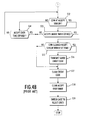
- step S1 the primary coin validation (in response to a coin at sensor station 5) is carried out at step S2.
- step S3 if the primary validation at S2 indicates the coin to be a true coin, the status of the accept gate 11 is checked at step S4. If the gate 11 is in the reject state, i.e. no drive signal is applied on line 9 to the gate driver 10 so that the gate is open, a check is carried out a step S5 to determine whether a coin accept signal x 4 is being produced by the accept coil C4. Thus, the steps S4 and S5 check that any previously validated coin or fraud has been cleared through the validator.
- step S6 de-energises line 9 ( Figure 2) in order to open the gate 11 to place it in its reject state.
- step S7 any credit code on line 14 is cleared to ensure that no credit is accumulated for the coin under test.
- step S5 the routine proceeds to steps S8 and S9 so as to start and undertimer and the overtimer (see Figures 3A and 3B). Also, at step S10, the value of the coin denomination for the true coin determined at step S2 is saved as a so-called credit code.
- step S11 a drive signal is applied to line 9 ( Figure 2) to operate gate driver 10 and thereby switch the gate 11 to an accept state in which it is closed, so as to direct coins to the coin accept path 13 ( Figure 1).
- this shows an interrupt routine for performing the auxiliary validation test.
- the coin that was validated at step S2 travels along the passageway shown in Figure 1 and, because the gate has been closed at step S11 ( Figure 4A) the coin moves towards the coin accept sensor coil arrangement C4a, b ( Figure 1).
- a coin accept pulse x 4 is produced and fed to the microprocessor. This is detected step S12 in Figure 4B.
- step S14 determines whether the trailing edge of the accept pulse x 4 falls within the acceptable time range t 3 and t 4 shown in Figure 3D, indicating that the coin has not dwelled for an unacceptably long or short time in the region of the accept coil C4 ( Figure 1). If the test of step S14 is passed, the credit code that was saved at step S10 is transmitted on line 14 ( Figure 2) at step S16, indicating the successful outcome of both the primary and auxiliary validation tests.
- the present invention provides a solution to this problem by selectively switching off one or more of the auxiliary tests when the rate of coin entry for valid coins exceeds a given threshold.
- auxiliary tests When coins are fed rapidly into the validator, it would be impossible to carry out a fraudulent operation with a coin on a string because there would be no time to insert and remove the fraudulent coin and in accordance with the invention, it has been appreciated that when the coin entry rate exceeds a given threshold, it is safe to discontinue with at least one or more of the auxiliary coin validation tests.
- Figure 5A illustrates the main validation routine
- Figures 5B and 5C illustrate interrupt routines which are commenced in response to each successful primary validation at step S2, the interrupt routines being linked to one another and to the primary routine as shown in the drawings.
- the undertimer is disabled when coins are fed into the validator at a rate greater than a given threshold.
- a successful outcome of the primary validation test performed at S2 is determined at S3. If the gate 11 is in its reject state and the accept sensor coil C4 is clear of coins, as determined at steps S4 and S5, the start accept undertimer is started at step S8 and the overtimer is started at step S9 as previously described.
- the memory of the microprocessor 7 is operationally partitioned to provide first and second stacks for credit codes hereinafter referred to as Stack 1 and Stack 2.
- the credit code for the first coin produced by the coin validation at S2 is stored in Stack 1 during step S10.
- the accept gate is switched to its accept state i.e. is dosed in order to direct the coin to the accept path 13.
- the first interrupt routine commences for the first coin at step S12 in order to determine when the coin reaches the accept sensor coil C4. If the coin produces an accept pulse x 4 between the times t 1 , t 2 produced by the overtimer and undertimer as determined by steps S13 and 14, the routine moves to step S15 to determine whether the coin clears the sensor coil C4 within a clearance time. If this occurs, the routine moves to step S21 and the credit code stored at step S10 for the coin, is transferred into Stack 2, the code being deleted from Stack 1 at step S22.
- the second interrupt routine ensures that the credit code associated with the coin is transmitted on line 14 ( Figure 2). More particularly, credit codes in Stack 2 are successively transmitted on line 14 by firstly getting the credit code from Stack 2 during step S23, clearing the code at S24 and transmitting the code at step S25. Step S26 determines if the Stack 2 is empty, and if not the routine shown in Figure 5C is repeated until it is fully clear.
- step S4 if the accept gate 11 remains in the reject state due to the acceptance process for the first coin, the routine does not automatically reject the second coin but instead skips past the steps S5 and S8.
- the routine assumes that because the gate 11 is not yet in its reject state, the accept sensor coil C4 will not yet be clear because the acceptance process for the first coin has not yet been completed.
- it has been appreciated that it is not necessary to start the accept undertimer (step S8) in this situation. Because the first and second coins are inserted in rapid succession, it would be impossible to perform a coin on a string type fraud and consequently, it is safe to disable the undertimer at step S8 in respect of the second coin.
- the credit code for the second coin produced during the second primary validation at S2 is stored at step S10 in Stack 1 and the accept gate 11 is maintained in its accept state at step S11.
- step S12 Figure 5B
- the undertimer will have already expired at step S13 because it has already expired due to the acceptance of the first coin and has not been restarted in response to the second coin. Therefore, as long as the overtimer has not expired before the coin reaches the accept sensor coil C4 (steps S12 and S14) the routine moves to step S15 for the second coin and the credit code for the second coin is transferred from Stack 1 to Stack 2 at step S21, as long as the second coin clears the sensor coil C4 within the predetermined clearance time as determined at step S15.
- the credit code for the second coin will thus be transmitted at step S25 by the routine shown in Figure 5C, in the manner previously explained.
- the routine has the advantage that the second coin can be accepted notwithstanding the fact that it closely follows the first coin and the primary validation for the second coin occurs during the time that the gate 11 is closed in order to handle acceptance of the first coin.
- the undertimer is automatically enabled again to ensure that the security provided by the auxiliary testing is maintained.
- auxiliary coin validation tests are disabled when the coin entry rate exceeds a given threshold. It would be possible to disable further ones of the auxiliary tests depending on the coin entry rate. For example, although not shown it would be possible to disable operation of the overtimer at step S14 and/or the clearance time check that is performed at step S13. This could be done for example in dependence upon the outcome of the test at step S4.
- the auxiliary tests may be progressively disabled as the coin entry rate increases.
- the routine may be extended to include further auxiliary validation tests such as the detection of coins travelling backwards through the validator and coins being detected at the accept sensor coil C4a when not expected.
- microprocessor can be rendered unresponsive to the outcome of the or each auxiliary validation test by either not performing the test itself or by disabling the outcome of the test in the relevant microprocessor routine.
- coin includes a token or other like item of credit.
- validator uses inductive sensors
- optical or mechanical sensors could be used, either at the primary validation testing station, or for the further sensor.
Landscapes
- Physics & Mathematics (AREA)
- General Physics & Mathematics (AREA)
- Testing Of Coins (AREA)
- Control Of Vending Devices And Auxiliary Devices For Vending Devices (AREA)
- Pinball Game Machines (AREA)
Claims (14)
- Münzgültigkeitsprüfvorrichtung, die folgendes umfasst:ein Mittel, das einen Durchgangsweeg (4) definiert, um zu testende Münzen (3) zu empfangen;Hauptgültigkeitstestmittel (5, C1, C2, C3), um Hauptpgültigkeitstests an Münzen durchzuführen, die den Durchgangsweg entlanggehen;ein Hilfsgültigkeitstestmittel (C4), um wenigstens einen Hilfsgültigkeitsstest an den Münzen zusätzlich zu den Testen durchzuführen, die von dem Haupttestmittel ausgeführt werden;ein Tormittel (11), um Münzen, die als gültig bestimmt sind, zu einem Annahmeweg zu richten, und Münzen, die als ungültig bestimmt sind, zu einem Zurückweisungsweg (12); undein Steuermittel (10), um den Betrieb des Tormittel in Abhängigkeit von dem Ergebnis der von den Haupt- und Hilfstestmitteln durchgeführten Haupt- und Hilfsgültigkeitstests zu steuern; gekennzeichnet durchein Mittel, um das Steuermittel auf das Ergebnis nicht reagierend zu machen, wenn eine Folge von Münzen mit einer Geschwindigkeit in den Durchgangsweg gebracht wird, die eine gegebene Schwelle überschreitet.
- Münzgültigkeitsprüfvorrichtung nach Anspruch 1, die ein Messfühlermittel (5) einschließt, um Münzen (3) zu erfassen, die den Durchgangsweg (4) entlang gehen, wobei das Hauptgültigkeitstestmittel (5, C1, C2, C3) auf das Messfühlermittel reagiert, um den Hauptgültigkeitstest durchzuführen.
- Münzgültigkeitsprüfvorrichtung nach Anspruch 2, in der das Messfühlermittel (5) wenigstens eine Induktorspule (C1, C2, C3) umfasst, um eine induktive Kupplung mit der Münze (3) zu bilden, und das Hauptgültigkeitstestmittel betrieben ist, um die Münze in Abhängigkeit von der induktiven Kuppling zu bewerten.
- Münzgültigkeitsprüfvorrichtung nach Anspruch 2 oder 3, in der das Hilfsgültigkeitstestmittel (4) einen weiteren Messfühler (C4) einschließt, und ein Mittel, um die Zeit zu bestimmen, zu der sich eine zu testende Münze (3) in die Nähe des weiteren Messfühlers bewegt.
- Münzgültigkeitsprüfvorrichtung nach Anspruch 4, in der das Hilfgültigkeitstestmittel (C4) ein Mittel einschließt, um zu bestimmen, ob die zu testende Münze (3) an dem weiteren Messfühler (C4) innerhalb einer Zeit ankommt, die kleiner als eine gegebene Schwelle ist.
- Münzgültigkeitsprüfvorrichtung nach Anspruch 4 oder 5, in der das Hilfgültigkeitstestmittel (C4) ein Mittel einschließt, um zu bestimmen, ob die zu testende Münze (3) an dem weiteren Messfühler (C4) innerhalb einer Zeit ankommt, die größer als eine gegebene Schwelle ist.
- Münzgültigkeitsprüfvorrichtung nach Anspruch 4, 5 oder 6, in der das Hilfgültigkeitstestmittel (C4) ein Mittel einschließt, um zu bestimmen, ob die zu testende Münze (3) für eine Zeit in der Nachbarschaft des weiteren Messfühlers (C4) bleibt, die kleiner als eine gegebene Schwelle ist.
- Münzgültigkeitsprüfvorrichtung nach Anspruch 4, 5, 6 oder 7, in der das Hilfgültigkeitstestmittel (C4) ein Mittel einschließt, um zu bestimmen, ob die zu testende Münze (3) für eine Zeit in der Nachbarschaft des weiteren Messfühlers (C4) bleibt, die größer als eine gegebene Schwelle ist.
- Münzgültigkeitsprüfvorrichtung nach einem der Ansprüche 4 bis 8, in der das Hilfgültigkeitstestmittel (C4) ein Mittel einschließt, um die Betriebseinstellung des Tormittels (11) aufzufinden.
- Münzgültigkeitsprüfvorrichtung nach Anspruch 9, in der das Steuermittel in Reaktion auf eine erfolgreiche Gültigkeitsprüfung einer ersten Münze (3) gefolgt von einem erfolgreichen Ergebnis des Hauptgültigkeitstests (5, C1, C2, C3) für eine zweite folgende Münze in Betrieb ist, um wenigstens einen der Hilfgültigkeitstests in Abhängigkeit von der Betriebseinstellung des Tormittels (11) außerstand zu setzen.
- Münzgültigkeitsprüfvorrichtung nach einem der Ansprüche 4 bis 10, in der das Hilfstestmittel (C4) einen Zeitgeber über der Zeit und einen Zeitrgeber unter der Zeit einschließt, um jeweilige maximal und minimal gestattete Zeiten für eine zu testende Münze zu definieren, um den weiteren Messfühler (C4) nach dem Hauptgültigkeitstest (5, C1, C2, C3) zu erreichen, und das Steuermittel betrieben ist, um den Betrieb des Zeitgebers unter der Zeit außerstand zu setzen, wenn aufeinanderfolgende Münzen (3) mit einer Geschwindigkeit in den Gültigkeitstester gebracht werden, die die gegebene Schwelle überschreitet.
- Verfahren zum Bewerten von Münzen (3), das folgendes umfasst:Durchführen von einem Hauptgültigkeitstest (5, C1, C2, C3) an Münzen, die einen Durchgangsweg (4) entlanggehen;Durchführen von wenigstens einem Hilfsgültigkeitstest (C4) auf den Münzen zusätzlich zu dem Hauptgültigkeitstest;Richten von Münzen, die als gültig bestimmt sind, auf einen Annahmeweg (13), und Münzen, die als ungültig bestimmt sind, auf einen Zurückweisungsweg (12) in Abhängigkeit von dem Ergebnis der Haupt- und Hilfsgültigkeitstests; gekennzeichnet durchNichtbeachten des Ergebnisses des Hilfsgültigkeitstests, wenn eine Folge von Münzen mit einer Geschwindigkeit in den Durchgangsweg gebracht wird, die eine gegebene Schwelle überschreitet.
- Verfahren nach Anspruch 12, in der der Hilfstest (C4) nicht durchgeführt wird, wenn die Münzenzubringungsgeschwindigkeit die Schwelle überschreitet.
- Verfahren nach Anspruch 12 oder 13, das einschließt, den Hilfstest durchzuführen, indem eine Zeitdauer überwacht wird, die eine Funktion der Zeit ist, die von einer zu testenden Münze (3) genommen wird, um sich von der Stelle, an der der Haupttest (5, C1, C2, C3) durchgeführt wird, zu einer Stelle in dem Annahmeweg (13) zu bewegen.
Applications Claiming Priority (3)
| Application Number | Priority Date | Filing Date | Title |
|---|---|---|---|
| GBGB9507257.5A GB9507257D0 (en) | 1995-04-07 | 1995-04-07 | Coin validation apparatus and method |
| GB9507257 | 1995-04-07 | ||
| PCT/GB1996/000826 WO1996031847A1 (en) | 1995-04-07 | 1996-04-03 | Coin validation apparatus and method |
Publications (2)
| Publication Number | Publication Date |
|---|---|
| EP0819286A1 EP0819286A1 (de) | 1998-01-21 |
| EP0819286B1 true EP0819286B1 (de) | 1999-07-07 |
Family
ID=10772716
Family Applications (1)
| Application Number | Title | Priority Date | Filing Date |
|---|---|---|---|
| EP96909234A Expired - Lifetime EP0819286B1 (de) | 1995-04-07 | 1996-04-03 | Vorrichtung und verfahren zum münzprüfen |
Country Status (10)
| Country | Link |
|---|---|
| US (1) | US6119844A (de) |
| EP (1) | EP0819286B1 (de) |
| JP (1) | JPH11503252A (de) |
| KR (1) | KR19980703706A (de) |
| CN (1) | CN1108592C (de) |
| AU (1) | AU696269B2 (de) |
| CA (1) | CA2217487A1 (de) |
| DE (1) | DE69603169D1 (de) |
| GB (1) | GB9507257D0 (de) |
| WO (1) | WO1996031847A1 (de) |
Families Citing this family (7)
| Publication number | Priority date | Publication date | Assignee | Title |
|---|---|---|---|---|
| JP2002024775A (ja) * | 2000-07-06 | 2002-01-25 | Nippon Conlux Co Ltd | コイン型icカード用リーダライタ |
| GB0218259D0 (en) * | 2002-08-06 | 2002-09-11 | Money Controls Ltd | Fraud prevention |
| DE10310474B4 (de) * | 2003-03-11 | 2007-05-03 | National Rejectors, Inc. Gmbh | Münzprüfer für Automaten mit einer Vorrichtung zur Verhinderung einer Manipulation |
| JP6638485B2 (ja) * | 2016-03-11 | 2020-01-29 | 富士電機株式会社 | 硬貨処理装置 |
| CN105894648A (zh) * | 2016-05-25 | 2016-08-24 | 武汉工程大学 | 一种硬币清点提取装置 |
| CN107301714A (zh) * | 2017-05-31 | 2017-10-27 | 江苏普世祥光电技术有限公司 | 一种硬币鉴伪及清分系统 |
| CN110349325B (zh) * | 2019-07-17 | 2021-04-23 | 绍兴市华获智能装备有限公司 | 一种用于银行的硬币、纸币清分机 |
Family Cites Families (29)
| Publication number | Priority date | Publication date | Assignee | Title |
|---|---|---|---|---|
| JPS542197A (en) * | 1977-06-07 | 1979-01-09 | Fuji Electric Co Ltd | Controlling method of coin screening device |
| US4385684A (en) * | 1979-07-17 | 1983-05-31 | Kabushiki Kaisha Nippon Coinco | Coin selection device |
| GB2093620B (en) * | 1981-02-11 | 1985-09-04 | Mars Inc | Checking coins |
| US4538719A (en) * | 1983-07-01 | 1985-09-03 | Hilgraeve, Incorporated | Electronic coin acceptor |
| GB2144252B (en) * | 1983-07-28 | 1987-04-23 | Mars Inc | Coin testing apparatus |
| ZA851248B (en) * | 1984-03-01 | 1985-11-27 | Mars Inc | Self tuning coin recognition system |
| JPS60262292A (ja) * | 1984-06-08 | 1985-12-25 | 株式会社田村電機製作所 | 硬貨検査装置 |
| US4686365A (en) * | 1984-12-24 | 1987-08-11 | American Cyanamid Company | Fourier transform ion cyclothon resonance mass spectrometer with spatially separated sources and detector |
| GB8500220D0 (en) * | 1985-01-04 | 1985-02-13 | Coin Controls | Discriminating between metallic articles |
| US4749074A (en) * | 1985-10-11 | 1988-06-07 | Matsushita Electric Industrial Co., Ltd. | Coin sorting apparatus with reference value correction system |
| JPS6327995A (ja) * | 1986-07-21 | 1988-02-05 | 株式会社田村電機製作所 | 硬貨選別装置 |
| US4845994A (en) * | 1988-02-29 | 1989-07-11 | Automatic Toll Systems, Inc. | Coin testing apparatus |
| US5155960A (en) * | 1988-03-29 | 1992-10-20 | Indal Furniture Systems A Division Of Indal Limited | Cam action connector for joining furniture panels |
| JPH06101052B2 (ja) * | 1988-06-30 | 1994-12-12 | 株式会社日本コンラックス | 硬貨識別装置 |
| GB2222903A (en) * | 1988-09-20 | 1990-03-21 | Plessey Telecomm | Coin validation apparatus |
| US4936435A (en) * | 1988-10-11 | 1990-06-26 | Unidynamics Corporation | Coin validating apparatus and method |
| JP2524823B2 (ja) * | 1988-11-02 | 1996-08-14 | 株式会社田村電機製作所 | 硬貨外径選別装置 |
| JPH0673151B2 (ja) * | 1988-12-14 | 1994-09-14 | サンデン株式会社 | 自動販売機の硬貨受入装置 |
| IT1232019B (it) * | 1989-02-23 | 1992-01-23 | Urmet Spa | Perfezionamento ai selezionatori di monete |
| GB8912522D0 (en) * | 1989-05-26 | 1989-07-19 | Coin Controls | Coin discrimination apparatus with temperature compensation |
| US5085309A (en) * | 1989-06-07 | 1992-02-04 | Adamson Phil A | Electronic coin detector |
| US5007520A (en) * | 1989-06-20 | 1991-04-16 | At&T Bell Laboratories | Microprocessor-controlled apparatus adaptable to environmental changes |
| GB9010766D0 (en) * | 1990-05-14 | 1990-07-04 | Coin Controls | Coin discrimination apparatus |
| GB2244364B (en) * | 1990-05-24 | 1994-03-09 | Coin Controls | Coin discrimination apparatus |
| US5226520A (en) * | 1991-05-02 | 1993-07-13 | Parker Donald O | Coin detector system |
| GB9117849D0 (en) * | 1991-08-19 | 1991-10-09 | Coin Controls | Coin discrimination apparatus |
| GB9120315D0 (en) * | 1991-09-24 | 1991-11-06 | Coin Controls | Coin discrimination apparatus |
| GB9120848D0 (en) * | 1991-10-01 | 1991-11-13 | Innovative Tech Ltd | Banknote validator |
| GB9226383D0 (en) * | 1992-12-18 | 1993-02-10 | Coin Controls | Coin sensing apparatus |
-
1995
- 1995-04-07 GB GBGB9507257.5A patent/GB9507257D0/en active Pending
-
1996
- 1996-04-03 KR KR1019970707106A patent/KR19980703706A/ko not_active Withdrawn
- 1996-04-03 EP EP96909234A patent/EP0819286B1/de not_active Expired - Lifetime
- 1996-04-03 US US08/930,723 patent/US6119844A/en not_active Expired - Fee Related
- 1996-04-03 CA CA002217487A patent/CA2217487A1/en not_active Abandoned
- 1996-04-03 AU AU52808/96A patent/AU696269B2/en not_active Ceased
- 1996-04-03 JP JP8530101A patent/JPH11503252A/ja active Pending
- 1996-04-03 CN CN96193134A patent/CN1108592C/zh not_active Expired - Fee Related
- 1996-04-03 WO PCT/GB1996/000826 patent/WO1996031847A1/en not_active Ceased
- 1996-04-03 DE DE69603169T patent/DE69603169D1/de not_active Expired - Lifetime
Also Published As
| Publication number | Publication date |
|---|---|
| CN1181145A (zh) | 1998-05-06 |
| DE69603169D1 (de) | 1999-08-12 |
| KR19980703706A (ko) | 1998-12-05 |
| EP0819286A1 (de) | 1998-01-21 |
| CA2217487A1 (en) | 1996-10-10 |
| WO1996031847A1 (en) | 1996-10-10 |
| CN1108592C (zh) | 2003-05-14 |
| JPH11503252A (ja) | 1999-03-23 |
| AU5280896A (en) | 1996-10-23 |
| AU696269B2 (en) | 1998-09-03 |
| US6119844A (en) | 2000-09-19 |
| GB9507257D0 (en) | 1995-05-31 |
Similar Documents
| Publication | Publication Date | Title |
|---|---|---|
| US5236071A (en) | Apparatus for detecting coins and method thereof | |
| AU648557B2 (en) | Coin discrimination apparatus | |
| US6119844A (en) | Coin validation apparatus and method | |
| EP1151419B1 (de) | Geldannahmevorrichtung | |
| JP4482166B2 (ja) | 硬貨選別装置 | |
| US20050061605A1 (en) | Fraud prevention | |
| AU761454B2 (en) | Vending machine | |
| EP1581914B1 (de) | Geldartikelakzeptor mit erweiterter sicherheit | |
| EP1581913B1 (de) | Verbessertes geldannahmegerät | |
| KR100279141B1 (ko) | 부정사용 방지기능을 갖는 전자식 주화선별기 및 그의 제어방법 | |
| JP2536655B2 (ja) | 硬貨検銭・計数装置の異常処理方法 | |
| JP3670905B2 (ja) | 硬貨識別装置 | |
| JP3175359B2 (ja) | 釣銭合わせ機能付コインメカニズム | |
| JP3598906B2 (ja) | 硬貨選別装置 | |
| JP3030564B2 (ja) | 硬貨処理装置 | |
| JP2998159B2 (ja) | 硬貨選別装置 | |
| JPH04184591A (ja) | 硬貨処理装置 | |
| JP2822360B2 (ja) | 貨幣識別機およびその貨幣受入方法 | |
| JPH06309543A (ja) | 硬貨選別装置 | |
| JPS58181186A (ja) | 硬貨払い出し制御装置 | |
| CN107180482A (zh) | 硬币处理装置 |
Legal Events
| Date | Code | Title | Description |
|---|---|---|---|
| PUAI | Public reference made under article 153(3) epc to a published international application that has entered the european phase |
Free format text: ORIGINAL CODE: 0009012 |
|
| 17P | Request for examination filed |
Effective date: 19971022 |
|
| AK | Designated contracting states |
Kind code of ref document: A1 Designated state(s): DE ES FR GB IT |
|
| 17Q | First examination report despatched |
Effective date: 19980327 |
|
| GRAG | Despatch of communication of intention to grant |
Free format text: ORIGINAL CODE: EPIDOS AGRA |
|
| GRAG | Despatch of communication of intention to grant |
Free format text: ORIGINAL CODE: EPIDOS AGRA |
|
| GRAH | Despatch of communication of intention to grant a patent |
Free format text: ORIGINAL CODE: EPIDOS IGRA |
|
| GRAH | Despatch of communication of intention to grant a patent |
Free format text: ORIGINAL CODE: EPIDOS IGRA |
|
| GRAA | (expected) grant |
Free format text: ORIGINAL CODE: 0009210 |
|
| AK | Designated contracting states |
Kind code of ref document: B1 Designated state(s): DE ES FR GB IT |
|
| PG25 | Lapsed in a contracting state [announced via postgrant information from national office to epo] |
Ref country code: IT Free format text: LAPSE BECAUSE OF FAILURE TO SUBMIT A TRANSLATION OF THE DESCRIPTION OR TO PAY THE FEE WITHIN THE PRESCRIBED TIME-LIMIT;WARNING: LAPSES OF ITALIAN PATENTS WITH EFFECTIVE DATE BEFORE 2007 MAY HAVE OCCURRED AT ANY TIME BEFORE 2007. THE CORRECT EFFECTIVE DATE MAY BE DIFFERENT FROM THE ONE RECORDED. Effective date: 19990707 Ref country code: FR Free format text: LAPSE BECAUSE OF FAILURE TO SUBMIT A TRANSLATION OF THE DESCRIPTION OR TO PAY THE FEE WITHIN THE PRESCRIBED TIME-LIMIT Effective date: 19990707 Ref country code: ES Free format text: THE PATENT HAS BEEN ANNULLED BY A DECISION OF A NATIONAL AUTHORITY Effective date: 19990707 |
|
| REF | Corresponds to: |
Ref document number: 69603169 Country of ref document: DE Date of ref document: 19990812 |
|
| PG25 | Lapsed in a contracting state [announced via postgrant information from national office to epo] |
Ref country code: DE Free format text: LAPSE BECAUSE OF FAILURE TO SUBMIT A TRANSLATION OF THE DESCRIPTION OR TO PAY THE FEE WITHIN THE PRESCRIBED TIME-LIMIT Effective date: 19991008 |
|
| EN | Fr: translation not filed | ||
| PLBE | No opposition filed within time limit |
Free format text: ORIGINAL CODE: 0009261 |
|
| STAA | Information on the status of an ep patent application or granted ep patent |
Free format text: STATUS: NO OPPOSITION FILED WITHIN TIME LIMIT |
|
| 26N | No opposition filed | ||
| REG | Reference to a national code |
Ref country code: GB Ref legal event code: IF02 |
|
| GBPC | Gb: european patent ceased through non-payment of renewal fee |
Effective date: 20070403 |
|
| PG25 | Lapsed in a contracting state [announced via postgrant information from national office to epo] |
Ref country code: GB Free format text: LAPSE BECAUSE OF NON-PAYMENT OF DUE FEES Effective date: 20070403 |
|
| PGFP | Annual fee paid to national office [announced via postgrant information from national office to epo] |
Ref country code: GB Payment date: 20060320 Year of fee payment: 11 |