EP0816517A1 - Unterdrücken der Bildung von Lanzenbären bei der Stahlerzeugung - Google Patents
Unterdrücken der Bildung von Lanzenbären bei der Stahlerzeugung Download PDFInfo
- Publication number
- EP0816517A1 EP0816517A1 EP97304189A EP97304189A EP0816517A1 EP 0816517 A1 EP0816517 A1 EP 0816517A1 EP 97304189 A EP97304189 A EP 97304189A EP 97304189 A EP97304189 A EP 97304189A EP 0816517 A1 EP0816517 A1 EP 0816517A1
- Authority
- EP
- European Patent Office
- Prior art keywords
- lance
- deskulling
- nozzles
- outer perimeter
- self
- Prior art date
- Legal status (The legal status is an assumption and is not a legal conclusion. Google has not performed a legal analysis and makes no representation as to the accuracy of the status listed.)
- Granted
Links
Images

Classifications
-
- F—MECHANICAL ENGINEERING; LIGHTING; HEATING; WEAPONS; BLASTING
- F27—FURNACES; KILNS; OVENS; RETORTS
- F27D—DETAILS OR ACCESSORIES OF FURNACES, KILNS, OVENS, OR RETORTS, IN SO FAR AS THEY ARE OF KINDS OCCURRING IN MORE THAN ONE KIND OF FURNACE
- F27D1/00—Casings; Linings; Walls; Roofs
- F27D1/16—Making or repairing linings increasing the durability of linings or breaking away linings
- F27D1/1694—Breaking away the lining or removing parts thereof
-
- C—CHEMISTRY; METALLURGY
- C21—METALLURGY OF IRON
- C21C—PROCESSING OF PIG-IRON, e.g. REFINING, MANUFACTURE OF WROUGHT-IRON OR STEEL; TREATMENT IN MOLTEN STATE OF FERROUS ALLOYS
- C21C5/00—Manufacture of carbon-steel, e.g. plain mild steel, medium carbon steel or cast steel or stainless steel
- C21C5/28—Manufacture of steel in the converter
- C21C5/42—Constructional features of converters
- C21C5/46—Details or accessories
- C21C5/4606—Lances or injectors
-
- C—CHEMISTRY; METALLURGY
- C21—METALLURGY OF IRON
- C21C—PROCESSING OF PIG-IRON, e.g. REFINING, MANUFACTURE OF WROUGHT-IRON OR STEEL; TREATMENT IN MOLTEN STATE OF FERROUS ALLOYS
- C21C5/00—Manufacture of carbon-steel, e.g. plain mild steel, medium carbon steel or cast steel or stainless steel
- C21C5/28—Manufacture of steel in the converter
- C21C5/42—Constructional features of converters
- C21C5/46—Details or accessories
- C21C5/4693—Skull removal; Cleaning of the converter mouth
Definitions
- This invention relates to preventing skulling of lances used in the process of making steel and, in particular, to preventing skulling of oxygen-blowing refining lances used to make steel in a basic oxygen furnace.
- BOF basic oxygen furnace
- post combustion in which the carbon monoxide gas is reacted with post combustion oxygen blown from a lance. Since relatively little carbon monoxide gas is generated at the beginning and at the end of a heat during refining, the amount of post combustion oxygen gas that is blown at these times for reaction with the carbon monoxide gas is either reduced or eliminated. By blowing the post combustion oxygen especially during the beginning and end of the heat, the refractory vessel lining may be eroded.
- the rate at which skull accumulates on a lance is converse to the rate at which carbon monoxide is generated during refining.
- the rate at which carbon monoxide is generated during refining is converse to the rate at which carbon monoxide is generated during refining.
- little skull will accumulate on the lance because the furnace is hottest at this time and skull only weakly adheres to the lance.
- Skull accumulation is greatest at the beginning and end of a heat.
- the absence of slag at the beginning of the heat and the condition of the slag at the end of the heat each leads to "sparking" of the metal in the furnace.
- skull comprising mostly molten metal contacts the lance and strongly adheres to it.
- Removing skull from a lance is a time consuming and costly process.
- three workers may be employed full time to clean skull build-up from the refining lances.
- the workers may first attempt to remove the skull from the lances by striking the skull with a metal rod. This technique may become ineffective as more skull accumulates on the lance. Therefore, the workers may cut the skull from the lance using a torch.
- the present invention pertains to preventing the accumulation of skull on refining lances used to make steel in a basic oxygen furnace.
- the accumulation of substantially all skull is prevented on self-cleaning lances constructed in accordance with the invention.
- the present invention provides a substantial savings in the production of steel in a basic oxygen furnace. Since skull accumulation on the refining lance is substantially prevented, conventional lance cleaning processes requiring extensive time, manpower and equipment are not required in the method of the present invention.
- the furnaces are able to be operated at maximum efficiency. Furnace operation is not delayed or burdened by extensive lance cleaning processes or by unscheduled transfers of heats that result therefrom.
- the present invention pertains to preventing the accumulation of skull on a lance including a lance body elongated along a longitudinal axis and having an upper end portion and a lower end portion.
- Main nozzles are located proximal to the lower end portion and are adapted to release an oxygen-containing gas.
- Upper deskulling nozzles are spaced upwardly from the lower end portion along the longitudinal axis and are adapted to release a deskulling gas, which is preferably an oxygen-containing gas.
- a first portion extends from the deskulling nozzles to the main nozzles and a second portion is disposed above the deskulling nozzles.
- the first portion has a smaller outer perimeter than an outer perimeter of the second portion.
- a transition from the first portion outer perimeter to the second portion outer perimeter forms a shoulder.
- the shoulder may extend at an angle of 90 degrees with respect to the longitudinal axis.
- the present invention may include at least one intermediate portion and deskulling nozzles disposed below the upper deskulling nozzles.
- the intermediate portion has an outer perimeter that is greater than the first portion outer perimeter and less than the second portion outer perimeter.
- Each of the deskulling nozzles preferably extends at an angle of not greater than 25 degrees with respect to the longitudinal axis and, more preferably, in the range of 5-25 degrees with respect to the longitudinal axis.
- Each of the deskulling nozzles may include a nozzle orifice that communicates with its associated shoulder.
- the shoulder has a width and each of the deskulling nozzles has an angle that avoids excessive heating of the lance while eliminating accumulation of substantially all skull on the lance.
- the present invention effectively prevents skull accumulation even at the beginning and end of a heat when skull formation on lances is greatest.
- oxygen gas may be released continuously from the deskulling nozzles throughout the refining process without any danger of eroding the furnace lining.
- post combustion oxygen is typically only blown intermittently, being reduced or turned off at the beginning and end of a heat, so as to avoid eroding the furnace lining.
- a method of cleaning a steelmaking lance according to the present invention generally includes the step of releasing the deskulling gas from the deskulling nozzles. Heat is generated by reacting the deskulling gas with the carbon monoxide gas released from the bath. The heat is applied to preferably both the first and second lance portions to prevent accumulation of substantially all skull on the lance.
- One aspect of the method of the present invention includes the step of releasing the deskulling gas from the deskulling nozzles along the first portion of the lance.
- the deskulling gas is reacted with the carbon monoxide gas released from the bath to generate heat.
- the heat is permitted to act on the lance to prevent accumulation of substantially all skull on the lance.
- One aspect of the method includes releasing the deskulling gas from each of the deskulling nozzles at an angle not greater than 25 degrees with respect to the longitudinal axis.
- the deskulling gas may be directed from the deskulling nozzles to blow skull from the lance.
- the heat is preferably permitted to act on both the first and second portions of the lance.
- the deskulling gas may be released throughout the entire steelmaking process.
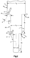
- the lance assembly 10 includes a lance body 12 with an outer surface 13.
- the body 12 is elongated along a longitudinal axis L and has an upper end portion 14 and a lower end portion 16.
- Main nozzles 18 include orifices 19 and are located proximal to the lower end portion 16.
- the main nozzles 18 are adapted to release an oxygen-containing gas for refining molten metal in a basic oxygen furnace.
- Upper deskulling nozzles 20 include orifices 21 and are spaced upwardly from the lower end portion 16.
- the deskulling nozzles 20 are adapted to release a deskulling gas for preventing the accumulation of skull on the outer lance surface 13.
- the lance assembly 10 also includes an upper stepped portion 22 to facilitate distributing the deskulling gas along the outer surface 13 to the main nozzles 18.
- a tip 24 is preferably disposed at the lower end portion 16.
- a section 26, which will be referred to herein as a distributor section, is located distally from the lower end portion 16. That is, the distributor section 26 is spaced from the lower end portion 16 along the longitudinal axis L.
- the main nozzles 18 are located proximal to the lower end portion 16, preferably at the bottom of the lance in the tip 24.
- the deskulling nozzles 20 are located distally from the lower end portion 16 in the distributor section 26.
- the deskulling nozzle orifices 21 of the distributor section 26 are preferably circumferentially equally spaced about the longitudinal axis L. Any suitable number of main and deskulling nozzle orifices may be used in the lance of the present invention as will be apparent to those skilled in the art in view of this disclosure.
- the lance of the present invention includes 3-5 main nozzle orifices and 8-14 deskulling nozzle orifices.
- the deskulling nozzle orifices 21 diverge radially outwardly from the longitudinal axis L. Each of the nozzle orifices 19, 21 extends along an associated axis A. All of the deskulling nozzle orifices of the present invention extend at an angle ⁇ with respect to an associated generally vertical axis y, which is parallel to the longitudinal axis L (Fig. 2).
- An oxygen-containing gas is preferably used as the deskulling gas. However, any gas that reacts with carbon monoxide gas to generate heat may be suitable for use in the present invention.
- the upper stepped portion 22 of the lance body 12 is defined by a first portion 28, a second portion 29 and a shoulder S 1 .
- the first portion 28 has a smaller outer diameter D 1 than the outer diameter D 2 of the second portion 29.
- a transition from the first portion outer diameter D 1 to the second portion outer diameter D 2 forms the shoulder S 1 .
- the first portion 28 extends axially from the upper deskulling nozzles 20 all the way to the main nozzles 18.
- the second portion 29 is located above and adjacent the upper deskulling nozzles 20.
- the second portion 29 may extend axially upwardly a few feet from the deskulling nozzles 20.
- the lance body 12 may include at least one intermediate stepped portion 30 between the upper stepped portion 22 and the lower end portion 16.
- an intermediate lance portion 31 has an outer diameter D 3 that is greater than the first portion outer diameter D 1 and less than the second portion outer diameter D 2 .
- the intermediate portion 31 is disposed along the first portion 28. The transition between the first portion outer diameter D 1 and the intermediate portion outer diameter D 3 forms a shoulder S 2 .
- the intermediate stepped portion 31 includes deskulling nozzles 21.
- the length of the intermediate portion 31 between the shoulder S 1 and the shoulder S 2 is l 1 .
- the length between the shoulder S 2 and the lowermost portion of the lance is l 2 .
- the shoulder S 1 has a width m 1 .
- the width of the shoulder S 2 is m 2 .
- the upper stepped portion 22 facilitates the flow of deskulling oxygen gas down the lance to the main nozzles 18. Since the first portion 28 has a smaller diameter than the second portion 29, the deskulling oxygen gas may flow downwardly along the entire length of the first portion 28.
- the deskulling nozzles 20 may extend into direct communication with their associated shoulder in the manner shown in Figure 2. This also facilitates flowing the deskulling oxygen gas along the length of the lance first portion 28. By flowing the deskulling oxygen gas down the entire length of the first portion 28, the entire first portion of the lance may be maintained skull-free.
- a predetermined shoulder-to-angle relationship is established in the present invention between the secondary nozzle angle ⁇ and the shoulder width m. This relationship is defined herein as that which avoids excessive heating of the lance body 12 while preventing accumulation of substantially all skull on the lance body 12. Heating of the lance body is excessive if, as a result, "scarfing" occurs, i.e. , the lance is burned or deteriorated.
- the shoulder-to-angle relationship may be influenced by other factors such as the number, location and size of the deskulling nozzles, the concentration of oxygen in the deskulling gas, the flow rate and velocity of the deskulling gas, the number of stepped portions, and the magnitude of the lengths l 1 and l 2 . For example, at deskulling nozzle angles ⁇ of 25 degrees compared to deskulling nozzle angles ⁇ of 5 degrees, the flow rate must be nearly doubled to enable the lance to be substantially skull-free.
- the angles ⁇ and the shoulder widths m may have any values that satisfy the shoulder-to-angle relationship of the present invention.
- the deskulling nozzle angle ⁇ and shoulder width m may vary from one stepped portion to another. Shoulder widths may range, for example, from about 1/2-2 inches and, in particular, from 1-2 inches, with about 1 inch being preferred.
- the deskulling nozzle angle ⁇ must not be greater than 25 degrees to heat the lance in the most effective manner and to avoid eroding the refractory furnace lining. More preferably, the deskulling nozzle orifices 21 extend by an angle in the range of from about 5-25 degrees with respect to the longitudinal axis and, in particular, in the range of from about 16-25 degrees from the longitudinal axis.
- the angle ⁇ may be made more acute. Conversely, if a shorter shoulder width m is desired, the angle ⁇ may be increased. Shoulder widths should not be of a size that increases the weight of the lance excessively or otherwise exceeds design constraints. As shown in Figure 2, the shoulders may be square with respect to their associated axis y, i.e. , they may extend at an angle of 90 degrees with respect thereto. The shoulders may also be inclined with respect to the associated axis y as shown in Figure 1.
- a housing assembly 32 is disposed at the upper end portion 14, and may have any structure known to those skilled in the art.
- the housing assembly 32 is supported by a lance carriage (not shown) in a manner known to those skilled in the art in view of this disclosure.
- a coolant supply pipe 34 and a coolant return pipe 36 are each connected to an associated opening in the housing assembly 32.
- An upper radially outer pipe 38 is welded to the housing assembly 32. The lower end of the outer pipe 38 is welded to an upper annular portion of the distributor section 26.
- a lower radially outermost pipe 40 is welded at its upper end to a lower radially outermost annular portion of the distributor section 26.
- the lower end of the pipe 40 is welded to an upper radially outermost annular portion of the tip 24.
- the upper end of the pipe 40 and the lower end of the pipe 38 are connected by the shoulder S 1 .
- an upper radially intermediate pipe 42 Spaced inwardly of and concentric with the pipe 38 is an upper radially intermediate pipe 42 connected at its upper end to the housing assembly 32. At its lower end the intermediate pipe 42 is welded to the distributor section 26. A lower radially intermediate pipe 44 is spaced inwardly of and concentric to the pipe 40. The upper end of the pipe 44 is welded to the distributor section 26. The lower end of the pipe 44 engages a sleeve 46 that is welded to a radially intermediate annular portion of the tip 24.
- a gas inlet pipe 48 is disposed at the upper end of the housing assembly 32 and extends upwardly therefrom where it is connected to a gas source in a manner known to those skilled in the art in view of this disclosure.
- An upper radially innermost pipe 50 is spaced inwardly of and concentric to the pipe 42. The pipe 50 is connected to the housing assembly 32 in fluid communication with the gas inlet pipe 48.
- the lower end of the pipe 50 is welded to an upper annular portion of the distributor section 26.
- a sleeve 52 extends upwardly from the upper radially innermost portion of the distributor section 26.
- Interior of and concentric to the lower intermediate pipe 44 is a lower radially innermost pipe 54.
- the upper end of the pipe 54 engages the sleeve 52.
- the lower end of the pipe 54 is connected to the radially innermost annular portion of the tip 24.
- a main gas flow passageway 56 is defined by portions of the lance including the gas inlet pipe 48, the pipe 50 and the pipe 54.
- the passageway 56 provides both the main nozzles 18 and the deskulling nozzles 20 with a single flow of pressurized gas through the lance. The gas flows from the gas source to the gas inlet pipe 48 and through the passageway 56.
- a coolant intake passageway 58 and a coolant outlet passageway 60 are defined by the lance assembly 10 as shown in Figure 1.
- a coolant such as water is introduced from a coolant supply (not shown) through the coolant intake passageway 58 and into the tip 24, through the coolant outlet passageway 60 and back to the coolant supply.
- the single circuit lance assembly 10 that is shown in Figure 1 is only one example of a lance assembly suitable for carrying out the present invention.
- the present invention may also be employed in other refining lance designs such as a double circuit lance assembly, which is well known to those skilled in the art.
- a double circuit lance assembly constructed to include the features of the present invention, the deskulling nozzles 20 would be in fluid communication with an deskulling fluid passageway.
- the main gas flow passageway 56 would lead only to the main nozzles 18 and would be isolated from fluid communication with the deskulling fluid passageway and the deskulling nozzles 20. Gas flow through the deskulling nozzles 20 would be able to be regulated independently of gas flow through the main nozzles 18.
- oxygen gas is blown down the main passageway 56 to the main nozzles 18.
- the deskulling gas is blown through the deskulling nozzle orifices 21 continuously from the beginning to the end of the refining process.
- the deskulling gas is directed by the deskulling nozzle orifices 21 where it travels along the first portion 28 all the way to the main nozzles 18.
- the self-cleaning refining lance 10 may be any suitable length, for example, approximately 78 feet in length.
- the lance typically extends about 18 feet into the furnace and is constructed of steel.
- the deskulling nozzles 20 of the upper stepped portion 22 are spaced a suitable distance upwardly from the lowermost portion of the lance to prevent substantially all skull accumulation on the lance. To this end, the deskulling nozzles are preferably spaced 6 or 8 feet from the lowermost portion of the lance.
- the pipes of the lance may range from 6 to 14 inches in diameter, for example.
- the upper radially outermost pipe 38 of the second portion 29 may be 14 inches in diameter and the lower radially outermost pipe 40 of the first portion 28 may be 10 inches in diameter. This results in a shoulder that is 2 inches wide.
- the nozzle orifices in the deskulling section and in the tip may be any suitable diameter.
- the deskulling nozzle orifices may be about 1/2 inch in diameter and the main nozzle orifices may be about 2 inches in diameter.
- One or more of the intermediate stepped portions 30 may be employed below the upper stepped portion 22 in certain circumstances including when a BOF has a sparking problem caused by the particular thermodynamics or chemistry of heats in that furnace, when the deskulling nozzles are located more than about 8 feet from the bottom of the lance or when wide deskulling nozzle angles or low flow rates are used.
- the flow rate through the deskulling nozzle orifices 20 is in the range of from about 500-1500 SCFM.
- a flow rate of 500 SCFM may be used, while at an deskulling nozzle angle of 25 degrees a flow rate of at least about 1000 SCFM may be required.
- the deskulling oxygen gas is blown at a velocity of about mach 1
- the deskulling oxygen gas is blown at a velocity in the range of from about mach 0.1-1.0.
- a single circuit lance constructed according to the invention had 10 deskulling nozzles spaced 6 feet from the lowermost portion of the lance that each extended at 18 degrees with respect to their associated vertical axes.
- the deskulling gas flow capacity of the lance was rated at 500 SCFM. During a 5 day trial wherein 96 heats were conducted, substantially all skull accumulation on the lance was prevented.
- skull accumulation on the lance is prevented primarily by two mechanisms, fluid flow (blowing of the deskulling oxygen gas along the lance at a relatively high velocity and flow rate) and heating the outside surface of the lance.
- the deskulling oxygen gas may physically blow from the lance any skull that is deposited on its first portion 28. Since the second lance portion 29 is disposed above the upper deskulling nozzles 20, skull accumulation there is unaffected by the fluid flow mechanism.
- the carbon monoxide gas released from the melt reacts with the deskulling oxygen released from the lance, which generates heat.
- the heat released from this reaction forms heat that is permitted to act upon the outer surface 13 of both the first and second portions of the lance.
- the outer surface 13 of the lance is heated to a temperature at which the bonding between the skull and the lance is weakened.
- the outer surface 13 may be heated to a lower temperature in the second portion 29 than in the first portion 28. Skull that forms on the first portion of the heated lance adheres to it very weakly and movement of the lance causes the skull to drop off the lance.
- Skull that forms on the second portion above the deskulling nozzles 20 also adheres there weakly, although somewhat stronger than in the first portion. Therefore, some skull may temporarily accumulate on the second portion 29 while it is in the furnace. In this event, hitting the lance with a rod as the lance is raised from the furnace easily removes any accumulation of skull from the second portion 29. Skull is removed quickly and easily from the second portion 29 without delaying the operation of the furnace.
Applications Claiming Priority (2)
| Application Number | Priority Date | Filing Date | Title |
|---|---|---|---|
| US670125 | 1991-03-15 | ||
| US08/670,125 US5830259A (en) | 1996-06-25 | 1996-06-25 | Preventing skull accumulation on a steelmaking lance |
Publications (2)
| Publication Number | Publication Date |
|---|---|
| EP0816517A1 true EP0816517A1 (de) | 1998-01-07 |
| EP0816517B1 EP0816517B1 (de) | 2003-03-19 |
Family
ID=24689102
Family Applications (1)
| Application Number | Title | Priority Date | Filing Date |
|---|---|---|---|
| EP97304189A Expired - Lifetime EP0816517B1 (de) | 1996-06-25 | 1997-06-16 | Unterdrücken der Bildung von Lanzenbären bei der Stahlerzeugung |
Country Status (8)
| Country | Link |
|---|---|
| US (1) | US5830259A (de) |
| EP (1) | EP0816517B1 (de) |
| JP (1) | JPH1030111A (de) |
| KR (1) | KR980002273A (de) |
| AU (1) | AU730594B2 (de) |
| BR (1) | BR9701471A (de) |
| CA (1) | CA2208470A1 (de) |
| DE (1) | DE69719870D1 (de) |
Cited By (1)
| Publication number | Priority date | Publication date | Assignee | Title |
|---|---|---|---|---|
| WO2012064996A1 (en) * | 2010-11-10 | 2012-05-18 | Berry Metal Company | Reinforced distributor for post-combustion lance |
Families Citing this family (6)
| Publication number | Priority date | Publication date | Assignee | Title |
|---|---|---|---|---|
| KR20040012167A (ko) * | 2002-08-01 | 2004-02-11 | 주식회사 포스코 | 전로 정련용 랜스 |
| US11786036B2 (en) | 2008-06-27 | 2023-10-17 | Ssw Advanced Technologies, Llc | Spill containing refrigerator shelf assembly |
| US8286561B2 (en) | 2008-06-27 | 2012-10-16 | Ssw Holding Company, Inc. | Spill containing refrigerator shelf assembly |
| DE102011085428A1 (de) | 2011-10-28 | 2013-05-02 | Schott Ag | Einlegeboden |
| US9732393B2 (en) * | 2012-07-10 | 2017-08-15 | Lumar Metals Ltda. | Blowing spear for fabrication of metals and maintenance of loading and blowing operational conditions |
| KR102221810B1 (ko) * | 2018-10-02 | 2021-02-26 | 톨맨테크놀로지인코포레이티드 | 내부 지지 어셈블리를 구비한 랜스 |
Citations (5)
| Publication number | Priority date | Publication date | Assignee | Title |
|---|---|---|---|---|
| US3488044A (en) * | 1967-05-01 | 1970-01-06 | Nat Steel Corp | Apparatus for refining metal |
| US3730505A (en) * | 1970-07-01 | 1973-05-01 | Centro Speriment Metallurg | Double delivery lance for refining the steel in the converter processes |
| EP0090452A1 (de) * | 1982-03-26 | 1983-10-05 | Hoogovens Groep B.V. | Verfahren zur Stahlerzeugung im Konverter aus Roheisen und Schrott |
| FR2542014A1 (fr) * | 1983-03-02 | 1984-09-07 | Solmer | Dispositif pour le decrassage des becs de convertisseur d'acierie |
| JPS61139616A (ja) * | 1984-12-11 | 1986-06-26 | Nisshin Steel Co Ltd | 転炉炉口付着物の除去方法 |
Family Cites Families (50)
| Publication number | Priority date | Publication date | Assignee | Title |
|---|---|---|---|---|
| US613598A (en) * | 1898-11-01 | Forming and drilling machine | ||
| CA876526A (en) * | 1971-07-27 | Kunioka Kazuo | Multi-outlet oxygen-fuel blowing lance | |
| US3320053A (en) * | 1964-09-25 | 1967-05-16 | Bethlehem Steel Corp | Method of injecting gases into steel melts |
| NL152602B (nl) * | 1968-05-09 | 1977-03-15 | Nippon Kokan Kk | Werkwijze voor het continu bereiden van staal. |
| GB1190137A (en) * | 1968-07-02 | 1970-04-29 | Inst Chernoi Metallurgii | Apparatus for Blowing Gas Through Molten Metal |
| US3594155A (en) * | 1968-10-30 | 1971-07-20 | Allegheny Ludlum Steel | Method for dynamically controlling decarburization of steel |
| US3932172A (en) * | 1969-02-20 | 1976-01-13 | Eisenwerk-Gesellschaft Maximilianshutte Mbh | Method and converter for refining pig-iron into steel |
| BE756083A (fr) * | 1969-09-11 | 1971-03-15 | Enya Ryosuke | Procede et dispositif pour la fabrication de metal en fusion destine a etre coule |
| US3700429A (en) * | 1970-01-05 | 1972-10-24 | Allegheny Ludlum Steel | Method of controlling vacuum decarburization |
| US3620455A (en) * | 1970-06-10 | 1971-11-16 | Berry Metal Co | Easily repairable gas injection lance |
| US3955964A (en) * | 1971-08-30 | 1976-05-11 | Koppers Company, Inc. | Process for making steel |
| SU414312A1 (de) * | 1972-03-23 | 1974-02-05 | ||
| SU502950A1 (ru) * | 1972-07-28 | 1976-02-15 | Институт черной металлургии | Водоохлаждаема фурма дл рафинировани металла |
| AT337736B (de) * | 1973-02-12 | 1977-07-11 | Voest Ag | Verfahren zum frischen von roheisen |
| SU499315A1 (ru) * | 1973-04-20 | 1976-01-15 | Институт Повышения Квалификации Руководящих Работников И Специалистов Черной Металлургии | Фурма дл продувки металла |
| US3861888A (en) * | 1973-06-28 | 1975-01-21 | Union Carbide Corp | Use of CO{HD 2 {B in argon-oxygen refining of molten metal |
| US3828850A (en) * | 1973-07-12 | 1974-08-13 | Black Sivalls & Bryson Inc | High temperature material introduction apparatus |
| JPS5414568B2 (de) * | 1973-08-28 | 1979-06-08 | ||
| JPS5112320A (ja) * | 1974-07-22 | 1976-01-30 | Nisshin Steel Co Ltd | Ganchitsusogokinkono seizoho |
| US4004920A (en) * | 1975-05-05 | 1977-01-25 | United States Steel Corporation | Method of producing low nitrogen steel |
| US4081270A (en) * | 1977-04-11 | 1978-03-28 | Union Carbide Corporation | Renitrogenation of basic-oxygen steels during decarburization |
| US4230274A (en) * | 1978-07-10 | 1980-10-28 | Pullman Berry Company | Lance for removing skulls from steelmaking vessels |
| US4322033A (en) * | 1978-07-10 | 1982-03-30 | Pullman Berry Company | Lance and method for removing skulls from steelmaking vessels |
| US4270949A (en) * | 1979-01-24 | 1981-06-02 | United Refractories, Inc. | Making of steel by the BOF process |
| US4490172A (en) * | 1979-06-29 | 1984-12-25 | Moore William H | Method of melting and refining steel and other ferrous alloys |
| US4348229A (en) * | 1980-08-22 | 1982-09-07 | Nippon Steel Corporation | Enamelling steel sheet |
| NL8104474A (nl) * | 1981-10-01 | 1983-05-02 | Estel Hoogovens Bv | Vloeistofgekoelde lans voor het blazen van zuurstof op een staalbad. |
| DE3231867A1 (de) * | 1982-08-27 | 1984-03-01 | Saar-Metallwerke GmbH, 6600 Saarbrücken | Zweikreislanze zum frischen von metallschmelzen |
| US4405365A (en) * | 1982-08-30 | 1983-09-20 | Pennsylvania Engineering Corporation | Method for the fabrication of special steels in metallurgical vessels |
| US4434005A (en) * | 1982-09-24 | 1984-02-28 | Arbed S. A. (Luxembourg) | Method of and apparatus for refining a melt containing solid cooling material |
| LU84433A1 (fr) * | 1982-10-22 | 1984-05-10 | Mecan Arbed Dommeldange S A R | Dispositif pour fournir des matieres gazeuses et solides a un bain de metal en voie d'affinage |
| NL8400393A (nl) * | 1984-02-08 | 1985-09-02 | Hoogovens Groep Bv | Vloeistofgekoelde lans voor het blazen van zuurstof op een staalbad. |
| US4653730A (en) * | 1984-11-27 | 1987-03-31 | Empco (Canada) Ltd. | Multi-purpose pyrometallurgical process enhancing device |
| US4564390A (en) * | 1984-12-21 | 1986-01-14 | Olin Corporation | Decarburizing a metal or metal alloy melt |
| US4615730A (en) * | 1985-04-30 | 1986-10-07 | Allegheny Ludlum Steel Corporation | Method for refining molten metal bath to control nitrogen |
| CA1293121C (en) * | 1985-08-20 | 1991-12-17 | Nobuyoshi Takashiba | Lance for blow-refinement in converter |
| SU1395682A1 (ru) * | 1986-11-04 | 1988-05-15 | Донецкий политехнический институт | Способ внепечной обработки стали при получении заготовок непрерывной разливкой |
| US4936908A (en) * | 1987-09-25 | 1990-06-26 | Nkk Corporation | Method for smelting and reducing iron ores |
| LU87156A1 (fr) * | 1988-03-11 | 1989-10-26 | Arbed | Tuyere pour lance d'affinage |
| JPH0717960B2 (ja) * | 1989-03-31 | 1995-03-01 | 新日本製鐵株式会社 | 磁気特性の優れた一方向性電磁鋼板の製造方法 |
| JP2782086B2 (ja) * | 1989-05-29 | 1998-07-30 | 新日本製鐵株式会社 | 磁気特性、皮膜特性ともに優れた一方向性電磁鋼板の製造方法 |
| EP0413306B1 (de) * | 1989-08-18 | 1996-04-10 | Nippon Steel Corporation | Verfahren zur Herstellung nichtorientierter Stahlbleche mit hoher magnetischer Flussdichte |
| BE1003516A3 (fr) * | 1989-10-09 | 1992-04-14 | Rech S Et Dev Desaar | Lance de soufflage multi-tubes. |
| US5251879A (en) * | 1989-09-29 | 1993-10-12 | Floyd John M | Top submerged injection with a shrouded lance |
| IT1237481B (it) * | 1989-12-22 | 1993-06-07 | Sviluppo Materiali Spa | Procedimento per la prodizione di lamierino magnetico semifinito a grano non orientato. |
| LU88023A1 (fr) * | 1991-10-30 | 1993-05-17 | Arbed | Lance de soufflage |
| JPH0625732A (ja) * | 1992-07-09 | 1994-02-01 | Nippon Steel Corp | 真空精錬用多機能ランス |
| US5377960A (en) * | 1993-03-01 | 1995-01-03 | Berry Metal Company | Oxygen/carbon blowing lance assembly |
| US5298053A (en) * | 1993-08-12 | 1994-03-29 | Bethlehem Steel Corporation | Consumable lance for oxygen injection and desulfurization and method |
| US5417739A (en) * | 1993-12-30 | 1995-05-23 | Ltv Steel Company, Inc. | Method of making high nitrogen content steel |
-
1996
- 1996-06-25 US US08/670,125 patent/US5830259A/en not_active Expired - Fee Related
-
1997
- 1997-02-26 AU AU14959/97A patent/AU730594B2/en not_active Ceased
- 1997-03-25 BR BR9701471A patent/BR9701471A/pt not_active IP Right Cessation
- 1997-03-31 KR KR1019970011912A patent/KR980002273A/ko not_active Application Discontinuation
- 1997-04-10 JP JP9091991A patent/JPH1030111A/ja active Pending
- 1997-06-16 DE DE69719870T patent/DE69719870D1/de not_active Expired - Lifetime
- 1997-06-16 EP EP97304189A patent/EP0816517B1/de not_active Expired - Lifetime
- 1997-06-23 CA CA002208470A patent/CA2208470A1/en not_active Abandoned
Patent Citations (5)
| Publication number | Priority date | Publication date | Assignee | Title |
|---|---|---|---|---|
| US3488044A (en) * | 1967-05-01 | 1970-01-06 | Nat Steel Corp | Apparatus for refining metal |
| US3730505A (en) * | 1970-07-01 | 1973-05-01 | Centro Speriment Metallurg | Double delivery lance for refining the steel in the converter processes |
| EP0090452A1 (de) * | 1982-03-26 | 1983-10-05 | Hoogovens Groep B.V. | Verfahren zur Stahlerzeugung im Konverter aus Roheisen und Schrott |
| FR2542014A1 (fr) * | 1983-03-02 | 1984-09-07 | Solmer | Dispositif pour le decrassage des becs de convertisseur d'acierie |
| JPS61139616A (ja) * | 1984-12-11 | 1986-06-26 | Nisshin Steel Co Ltd | 転炉炉口付着物の除去方法 |
Non-Patent Citations (1)
| Title |
|---|
| PATENT ABSTRACTS OF JAPAN vol. 010, no. 335 (C - 384) 13 November 1986 (1986-11-13) * |
Cited By (2)
| Publication number | Priority date | Publication date | Assignee | Title |
|---|---|---|---|---|
| WO2012064996A1 (en) * | 2010-11-10 | 2012-05-18 | Berry Metal Company | Reinforced distributor for post-combustion lance |
| RU2593052C2 (ru) * | 2010-11-10 | 2016-07-27 | Берри Метал Кампани, Сша | Армированный распределитель для фурмы для дожигания |
Also Published As
| Publication number | Publication date |
|---|---|
| CA2208470A1 (en) | 1997-12-25 |
| AU1495997A (en) | 1998-01-15 |
| JPH1030111A (ja) | 1998-02-03 |
| DE69719870D1 (de) | 2003-04-24 |
| AU730594B2 (en) | 2001-03-08 |
| BR9701471A (pt) | 1998-11-17 |
| US5830259A (en) | 1998-11-03 |
| EP0816517B1 (de) | 2003-03-19 |
| KR980002273A (ko) | 1998-03-30 |
Similar Documents
| Publication | Publication Date | Title |
|---|---|---|
| RU2154110C2 (ru) | Устройство для производства расплавленного передельного чугуна | |
| CA2066455C (en) | Top submerged injection with a shrouded lance | |
| US5830259A (en) | Preventing skull accumulation on a steelmaking lance | |
| CN105612263A (zh) | 用于增强浸没式燃烧的顶部浸没式喷射喷枪 | |
| AU2014335829A1 (en) | Top submerged injection lance for enhanced submerged combustion | |
| US2965370A (en) | Oxygen lance with bent tip | |
| JP5298543B2 (ja) | 転炉操業方法 | |
| CA1270638A (en) | Copper converter | |
| JPS63206420A (ja) | 転炉等の吹錬用ランス | |
| JP3297797B2 (ja) | ランス及びこのランスを用いた炉内付着地金の除去方法 | |
| US4171216A (en) | Process for refining non-ferrous matte | |
| JP2848010B2 (ja) | 溶融金属精錬用上吹ランス | |
| JP2917848B2 (ja) | 転炉吹錬兼炉口地金溶解用ランス | |
| JP2699778B2 (ja) | 溶射補修装置 | |
| JPH10287909A (ja) | 転炉吹錬兼炉口地金溶解用上吹きランス | |
| AU640955B2 (en) | Top submerged injection with a shrouded lance | |
| JPH06248323A (ja) | 転炉における炉口付着地金の除去方法 | |
| US5700144A (en) | Method and apparatus for thermal treatment of solids | |
| JP2000096121A (ja) | 転炉型精錬炉における地金付着抑制吹錬方法 | |
| JP3849571B2 (ja) | 転炉吹錬方法 | |
| JP5488025B2 (ja) | 転炉炉口付着地金の溶解方法 | |
| JP2000096119A (ja) | 転炉型精錬炉における地金付着抑制吹錬方法 | |
| JP2876955B2 (ja) | ガス吹き込み羽口を有する転炉型精錬容器の補修方法 | |
| RU1768648C (ru) | Фурма дл продувки металла в конвертере | |
| JPH11140525A (ja) | 炉口及び炉内側壁地金の付着を抑制する転炉吹錬方法及び転炉用ランス装置 |
Legal Events
| Date | Code | Title | Description |
|---|---|---|---|
| PUAI | Public reference made under article 153(3) epc to a published international application that has entered the european phase |
Free format text: ORIGINAL CODE: 0009012 |
|
| AK | Designated contracting states |
Kind code of ref document: A1 Designated state(s): BE DE FR GB NL |
|
| 17P | Request for examination filed |
Effective date: 19980703 |
|
| AKX | Designation fees paid |
Free format text: BE DE FR GB NL |
|
| RBV | Designated contracting states (corrected) |
Designated state(s): BE DE FR GB NL |
|
| 17Q | First examination report despatched |
Effective date: 19991216 |
|
| GRAH | Despatch of communication of intention to grant a patent |
Free format text: ORIGINAL CODE: EPIDOS IGRA |
|
| GRAH | Despatch of communication of intention to grant a patent |
Free format text: ORIGINAL CODE: EPIDOS IGRA |
|
| GRAA | (expected) grant |
Free format text: ORIGINAL CODE: 0009210 |
|
| AK | Designated contracting states |
Designated state(s): BE DE FR GB NL |
|
| PG25 | Lapsed in a contracting state [announced via postgrant information from national office to epo] |
Ref country code: NL Free format text: LAPSE BECAUSE OF FAILURE TO SUBMIT A TRANSLATION OF THE DESCRIPTION OR TO PAY THE FEE WITHIN THE PRESCRIBED TIME-LIMIT Effective date: 20030319 Ref country code: FR Free format text: LAPSE BECAUSE OF FAILURE TO SUBMIT A TRANSLATION OF THE DESCRIPTION OR TO PAY THE FEE WITHIN THE PRESCRIBED TIME-LIMIT Effective date: 20030319 Ref country code: BE Free format text: LAPSE BECAUSE OF FAILURE TO SUBMIT A TRANSLATION OF THE DESCRIPTION OR TO PAY THE FEE WITHIN THE PRESCRIBED TIME-LIMIT Effective date: 20030319 |
|
| REG | Reference to a national code |
Ref country code: GB Ref legal event code: FG4D |
|
| REF | Corresponds to: |
Ref document number: 69719870 Country of ref document: DE Date of ref document: 20030424 Kind code of ref document: P |
|
| PG25 | Lapsed in a contracting state [announced via postgrant information from national office to epo] |
Ref country code: GB Free format text: LAPSE BECAUSE OF NON-PAYMENT OF DUE FEES Effective date: 20030619 |
|
| PG25 | Lapsed in a contracting state [announced via postgrant information from national office to epo] |
Ref country code: DE Free format text: LAPSE BECAUSE OF FAILURE TO SUBMIT A TRANSLATION OF THE DESCRIPTION OR TO PAY THE FEE WITHIN THE PRESCRIBED TIME-LIMIT Effective date: 20030621 |
|
| NLV1 | Nl: lapsed or annulled due to failure to fulfill the requirements of art. 29p and 29m of the patents act | ||
| PLBE | No opposition filed within time limit |
Free format text: ORIGINAL CODE: 0009261 |
|
| STAA | Information on the status of an ep patent application or granted ep patent |
Free format text: STATUS: NO OPPOSITION FILED WITHIN TIME LIMIT |
|
| GBPC | Gb: european patent ceased through non-payment of renewal fee |
Effective date: 20030619 |
|
| EN | Fr: translation not filed | ||
| 26N | No opposition filed |
Effective date: 20031222 |