EP0814710B1 - Vorrichtung zur wiederherstellung von gelenkknorpeldefekten - Google Patents
Vorrichtung zur wiederherstellung von gelenkknorpeldefekten Download PDFInfo
- Publication number
- EP0814710B1 EP0814710B1 EP96905476A EP96905476A EP0814710B1 EP 0814710 B1 EP0814710 B1 EP 0814710B1 EP 96905476 A EP96905476 A EP 96905476A EP 96905476 A EP96905476 A EP 96905476A EP 0814710 B1 EP0814710 B1 EP 0814710B1
- Authority
- EP
- European Patent Office
- Prior art keywords
- bone
- stem
- internal
- bone plug
- proximal
- Prior art date
- Legal status (The legal status is an assumption and is not a legal conclusion. Google has not performed a legal analysis and makes no representation as to the accuracy of the status listed.)
- Expired - Lifetime
Links
- 230000008439 repair process Effects 0.000 title abstract description 9
- 206010061762 Chondropathy Diseases 0.000 title description 9
- 210000000988 bone and bone Anatomy 0.000 claims abstract description 213
- 230000033001 locomotion Effects 0.000 claims abstract description 26
- 230000013011 mating Effects 0.000 claims abstract description 7
- 238000003780 insertion Methods 0.000 claims abstract description 6
- 230000037431 insertion Effects 0.000 claims abstract description 6
- 210000001188 articular cartilage Anatomy 0.000 abstract description 42
- 238000000034 method Methods 0.000 abstract description 19
- 230000002950 deficient Effects 0.000 abstract description 8
- 230000007547 defect Effects 0.000 description 15
- 210000000845 cartilage Anatomy 0.000 description 14
- 210000000689 upper leg Anatomy 0.000 description 10
- 239000010410 layer Substances 0.000 description 9
- 238000001356 surgical procedure Methods 0.000 description 6
- 210000002303 tibia Anatomy 0.000 description 6
- 210000001519 tissue Anatomy 0.000 description 6
- 210000003127 knee Anatomy 0.000 description 5
- 206010007710 Cartilage injury Diseases 0.000 description 4
- 208000014674 injury Diseases 0.000 description 4
- 239000000463 material Substances 0.000 description 4
- 230000005499 meniscus Effects 0.000 description 4
- 230000002093 peripheral effect Effects 0.000 description 4
- 201000009859 Osteochondrosis Diseases 0.000 description 3
- 210000000629 knee joint Anatomy 0.000 description 3
- 108010071942 Colony-Stimulating Factors Proteins 0.000 description 2
- 102100039620 Granulocyte-macrophage colony-stimulating factor Human genes 0.000 description 2
- 102000010780 Platelet-Derived Growth Factor Human genes 0.000 description 2
- 108010038512 Platelet-Derived Growth Factor Proteins 0.000 description 2
- 208000027418 Wounds and injury Diseases 0.000 description 2
- 239000012790 adhesive layer Substances 0.000 description 2
- 230000006378 damage Effects 0.000 description 2
- 230000000694 effects Effects 0.000 description 2
- 238000011156 evaluation Methods 0.000 description 2
- 208000007656 osteochondritis dissecans Diseases 0.000 description 2
- 210000004285 patellofemoral joint Anatomy 0.000 description 2
- 230000002980 postoperative effect Effects 0.000 description 2
- 210000004353 tibial menisci Anatomy 0.000 description 2
- 230000008733 trauma Effects 0.000 description 2
- 206010003694 Atrophy Diseases 0.000 description 1
- 102000008186 Collagen Human genes 0.000 description 1
- 108010035532 Collagen Proteins 0.000 description 1
- 108010049003 Fibrinogen Proteins 0.000 description 1
- 102000008946 Fibrinogen Human genes 0.000 description 1
- 102000003974 Fibroblast growth factor 2 Human genes 0.000 description 1
- 108090000379 Fibroblast growth factor 2 Proteins 0.000 description 1
- 241000282412 Homo Species 0.000 description 1
- 241000124008 Mammalia Species 0.000 description 1
- 208000002804 Osteochondritis Diseases 0.000 description 1
- 102000004264 Osteopontin Human genes 0.000 description 1
- 108010081689 Osteopontin Proteins 0.000 description 1
- 238000012274 Preoperative evaluation Methods 0.000 description 1
- 108090000190 Thrombin Proteins 0.000 description 1
- 230000009471 action Effects 0.000 description 1
- 206010003246 arthritis Diseases 0.000 description 1
- 230000037444 atrophy Effects 0.000 description 1
- 239000000227 bioadhesive Substances 0.000 description 1
- 230000037182 bone density Effects 0.000 description 1
- 230000008468 bone growth Effects 0.000 description 1
- 230000037118 bone strength Effects 0.000 description 1
- 239000004568 cement Substances 0.000 description 1
- 229920001436 collagen Polymers 0.000 description 1
- 210000002808 connective tissue Anatomy 0.000 description 1
- 230000001054 cortical effect Effects 0.000 description 1
- 230000008878 coupling Effects 0.000 description 1
- 238000010168 coupling process Methods 0.000 description 1
- 238000005859 coupling reaction Methods 0.000 description 1
- 230000001419 dependent effect Effects 0.000 description 1
- 230000006866 deterioration Effects 0.000 description 1
- 238000000605 extraction Methods 0.000 description 1
- 229940012952 fibrinogen Drugs 0.000 description 1
- 239000002657 fibrous material Substances 0.000 description 1
- 210000002082 fibula Anatomy 0.000 description 1
- 239000012530 fluid Substances 0.000 description 1
- 239000012634 fragment Substances 0.000 description 1
- 230000012010 growth Effects 0.000 description 1
- 238000003306 harvesting Methods 0.000 description 1
- 230000035876 healing Effects 0.000 description 1
- 208000015181 infectious disease Diseases 0.000 description 1
- 238000012986 modification Methods 0.000 description 1
- 230000004048 modification Effects 0.000 description 1
- 230000000921 morphogenic effect Effects 0.000 description 1
- 230000000399 orthopedic effect Effects 0.000 description 1
- 238000012856 packing Methods 0.000 description 1
- 230000035515 penetration Effects 0.000 description 1
- 230000008569 process Effects 0.000 description 1
- 230000000750 progressive effect Effects 0.000 description 1
- 230000001737 promoting effect Effects 0.000 description 1
- 102000004169 proteins and genes Human genes 0.000 description 1
- 108090000623 proteins and genes Proteins 0.000 description 1
- 238000010079 rubber tapping Methods 0.000 description 1
- 239000000565 sealant Substances 0.000 description 1
- 238000009958 sewing Methods 0.000 description 1
- 230000035939 shock Effects 0.000 description 1
- 239000007787 solid Substances 0.000 description 1
- 210000005065 subchondral bone plate Anatomy 0.000 description 1
- 239000000126 substance Substances 0.000 description 1
- 229910000811 surgical stainless steel Inorganic materials 0.000 description 1
- 239000010966 surgical stainless steel Substances 0.000 description 1
- 230000008961 swelling Effects 0.000 description 1
- 238000012360 testing method Methods 0.000 description 1
- 229960004072 thrombin Drugs 0.000 description 1
- 230000002792 vascular Effects 0.000 description 1
Images


Classifications
-
- A—HUMAN NECESSITIES
- A61—MEDICAL OR VETERINARY SCIENCE; HYGIENE
- A61B—DIAGNOSIS; SURGERY; IDENTIFICATION
- A61B17/00—Surgical instruments, devices or methods
- A61B17/32—Surgical cutting instruments
- A61B17/3205—Excision instruments
- A61B17/32053—Punch like cutting instruments, e.g. using a cylindrical or oval knife
-
- A—HUMAN NECESSITIES
- A61—MEDICAL OR VETERINARY SCIENCE; HYGIENE
- A61B—DIAGNOSIS; SURGERY; IDENTIFICATION
- A61B17/00—Surgical instruments, devices or methods
- A61B17/16—Instruments for performing osteoclasis; Drills or chisels for bones; Trepans
- A61B17/1637—Hollow drills or saws producing a curved cut, e.g. cylindrical
-
- A—HUMAN NECESSITIES
- A61—MEDICAL OR VETERINARY SCIENCE; HYGIENE
- A61B—DIAGNOSIS; SURGERY; IDENTIFICATION
- A61B17/00—Surgical instruments, devices or methods
- A61B17/16—Instruments for performing osteoclasis; Drills or chisels for bones; Trepans
- A61B17/1662—Instruments for performing osteoclasis; Drills or chisels for bones; Trepans for particular parts of the body
- A61B17/1675—Instruments for performing osteoclasis; Drills or chisels for bones; Trepans for particular parts of the body for the knee
-
- A—HUMAN NECESSITIES
- A61—MEDICAL OR VETERINARY SCIENCE; HYGIENE
- A61F—FILTERS IMPLANTABLE INTO BLOOD VESSELS; PROSTHESES; DEVICES PROVIDING PATENCY TO, OR PREVENTING COLLAPSING OF, TUBULAR STRUCTURES OF THE BODY, e.g. STENTS; ORTHOPAEDIC, NURSING OR CONTRACEPTIVE DEVICES; FOMENTATION; TREATMENT OR PROTECTION OF EYES OR EARS; BANDAGES, DRESSINGS OR ABSORBENT PADS; FIRST-AID KITS
- A61F2/00—Filters implantable into blood vessels; Prostheses, i.e. artificial substitutes or replacements for parts of the body; Appliances for connecting them with the body; Devices providing patency to, or preventing collapsing of, tubular structures of the body, e.g. stents
- A61F2/02—Prostheses implantable into the body
- A61F2/30—Joints
- A61F2/30756—Cartilage endoprostheses
-
- A—HUMAN NECESSITIES
- A61—MEDICAL OR VETERINARY SCIENCE; HYGIENE
- A61F—FILTERS IMPLANTABLE INTO BLOOD VESSELS; PROSTHESES; DEVICES PROVIDING PATENCY TO, OR PREVENTING COLLAPSING OF, TUBULAR STRUCTURES OF THE BODY, e.g. STENTS; ORTHOPAEDIC, NURSING OR CONTRACEPTIVE DEVICES; FOMENTATION; TREATMENT OR PROTECTION OF EYES OR EARS; BANDAGES, DRESSINGS OR ABSORBENT PADS; FIRST-AID KITS
- A61F2/00—Filters implantable into blood vessels; Prostheses, i.e. artificial substitutes or replacements for parts of the body; Appliances for connecting them with the body; Devices providing patency to, or preventing collapsing of, tubular structures of the body, e.g. stents
- A61F2/02—Prostheses implantable into the body
- A61F2/30—Joints
- A61F2/46—Special tools for implanting artificial joints
- A61F2/4601—Special tools for implanting artificial joints for introducing bone substitute, for implanting bone graft implants or for compacting them in the bone cavity
-
- A—HUMAN NECESSITIES
- A61—MEDICAL OR VETERINARY SCIENCE; HYGIENE
- A61F—FILTERS IMPLANTABLE INTO BLOOD VESSELS; PROSTHESES; DEVICES PROVIDING PATENCY TO, OR PREVENTING COLLAPSING OF, TUBULAR STRUCTURES OF THE BODY, e.g. STENTS; ORTHOPAEDIC, NURSING OR CONTRACEPTIVE DEVICES; FOMENTATION; TREATMENT OR PROTECTION OF EYES OR EARS; BANDAGES, DRESSINGS OR ABSORBENT PADS; FIRST-AID KITS
- A61F2/00—Filters implantable into blood vessels; Prostheses, i.e. artificial substitutes or replacements for parts of the body; Appliances for connecting them with the body; Devices providing patency to, or preventing collapsing of, tubular structures of the body, e.g. stents
- A61F2/02—Prostheses implantable into the body
- A61F2/30—Joints
- A61F2/46—Special tools for implanting artificial joints
- A61F2/4603—Special tools for implanting artificial joints for insertion or extraction of endoprosthetic joints or of accessories thereof
- A61F2/4618—Special tools for implanting artificial joints for insertion or extraction of endoprosthetic joints or of accessories thereof of cartilage
-
- A—HUMAN NECESSITIES
- A61—MEDICAL OR VETERINARY SCIENCE; HYGIENE
- A61F—FILTERS IMPLANTABLE INTO BLOOD VESSELS; PROSTHESES; DEVICES PROVIDING PATENCY TO, OR PREVENTING COLLAPSING OF, TUBULAR STRUCTURES OF THE BODY, e.g. STENTS; ORTHOPAEDIC, NURSING OR CONTRACEPTIVE DEVICES; FOMENTATION; TREATMENT OR PROTECTION OF EYES OR EARS; BANDAGES, DRESSINGS OR ABSORBENT PADS; FIRST-AID KITS
- A61F2/00—Filters implantable into blood vessels; Prostheses, i.e. artificial substitutes or replacements for parts of the body; Appliances for connecting them with the body; Devices providing patency to, or preventing collapsing of, tubular structures of the body, e.g. stents
- A61F2/02—Prostheses implantable into the body
- A61F2/30—Joints
- A61F2/38—Joints for elbows or knees
- A61F2/3859—Femoral components
-
- A—HUMAN NECESSITIES
- A61—MEDICAL OR VETERINARY SCIENCE; HYGIENE
- A61F—FILTERS IMPLANTABLE INTO BLOOD VESSELS; PROSTHESES; DEVICES PROVIDING PATENCY TO, OR PREVENTING COLLAPSING OF, TUBULAR STRUCTURES OF THE BODY, e.g. STENTS; ORTHOPAEDIC, NURSING OR CONTRACEPTIVE DEVICES; FOMENTATION; TREATMENT OR PROTECTION OF EYES OR EARS; BANDAGES, DRESSINGS OR ABSORBENT PADS; FIRST-AID KITS
- A61F2/00—Filters implantable into blood vessels; Prostheses, i.e. artificial substitutes or replacements for parts of the body; Appliances for connecting them with the body; Devices providing patency to, or preventing collapsing of, tubular structures of the body, e.g. stents
- A61F2/02—Prostheses implantable into the body
- A61F2/28—Bones
- A61F2002/2835—Bone graft implants for filling a bony defect or an endoprosthesis cavity, e.g. by synthetic material or biological material
- A61F2002/2839—Bone plugs or bone graft dowels
-
- A—HUMAN NECESSITIES
- A61—MEDICAL OR VETERINARY SCIENCE; HYGIENE
- A61F—FILTERS IMPLANTABLE INTO BLOOD VESSELS; PROSTHESES; DEVICES PROVIDING PATENCY TO, OR PREVENTING COLLAPSING OF, TUBULAR STRUCTURES OF THE BODY, e.g. STENTS; ORTHOPAEDIC, NURSING OR CONTRACEPTIVE DEVICES; FOMENTATION; TREATMENT OR PROTECTION OF EYES OR EARS; BANDAGES, DRESSINGS OR ABSORBENT PADS; FIRST-AID KITS
- A61F2/00—Filters implantable into blood vessels; Prostheses, i.e. artificial substitutes or replacements for parts of the body; Appliances for connecting them with the body; Devices providing patency to, or preventing collapsing of, tubular structures of the body, e.g. stents
- A61F2/02—Prostheses implantable into the body
- A61F2/30—Joints
- A61F2002/30001—Additional features of subject-matter classified in A61F2/28, A61F2/30 and subgroups thereof
- A61F2002/30108—Shapes
- A61F2002/30199—Three-dimensional shapes
- A61F2002/30224—Three-dimensional shapes cylindrical
-
- A—HUMAN NECESSITIES
- A61—MEDICAL OR VETERINARY SCIENCE; HYGIENE
- A61F—FILTERS IMPLANTABLE INTO BLOOD VESSELS; PROSTHESES; DEVICES PROVIDING PATENCY TO, OR PREVENTING COLLAPSING OF, TUBULAR STRUCTURES OF THE BODY, e.g. STENTS; ORTHOPAEDIC, NURSING OR CONTRACEPTIVE DEVICES; FOMENTATION; TREATMENT OR PROTECTION OF EYES OR EARS; BANDAGES, DRESSINGS OR ABSORBENT PADS; FIRST-AID KITS
- A61F2/00—Filters implantable into blood vessels; Prostheses, i.e. artificial substitutes or replacements for parts of the body; Appliances for connecting them with the body; Devices providing patency to, or preventing collapsing of, tubular structures of the body, e.g. stents
- A61F2/02—Prostheses implantable into the body
- A61F2/30—Joints
- A61F2/30756—Cartilage endoprostheses
- A61F2002/30759—Mosaicplasty, i.e. using a plurality of individual cartilage plugs for filling a substantial cartilage defect
-
- A—HUMAN NECESSITIES
- A61—MEDICAL OR VETERINARY SCIENCE; HYGIENE
- A61F—FILTERS IMPLANTABLE INTO BLOOD VESSELS; PROSTHESES; DEVICES PROVIDING PATENCY TO, OR PREVENTING COLLAPSING OF, TUBULAR STRUCTURES OF THE BODY, e.g. STENTS; ORTHOPAEDIC, NURSING OR CONTRACEPTIVE DEVICES; FOMENTATION; TREATMENT OR PROTECTION OF EYES OR EARS; BANDAGES, DRESSINGS OR ABSORBENT PADS; FIRST-AID KITS
- A61F2/00—Filters implantable into blood vessels; Prostheses, i.e. artificial substitutes or replacements for parts of the body; Appliances for connecting them with the body; Devices providing patency to, or preventing collapsing of, tubular structures of the body, e.g. stents
- A61F2/02—Prostheses implantable into the body
- A61F2/30—Joints
- A61F2/30756—Cartilage endoprostheses
- A61F2002/30764—Cartilage harvest sites
-
- A—HUMAN NECESSITIES
- A61—MEDICAL OR VETERINARY SCIENCE; HYGIENE
- A61F—FILTERS IMPLANTABLE INTO BLOOD VESSELS; PROSTHESES; DEVICES PROVIDING PATENCY TO, OR PREVENTING COLLAPSING OF, TUBULAR STRUCTURES OF THE BODY, e.g. STENTS; ORTHOPAEDIC, NURSING OR CONTRACEPTIVE DEVICES; FOMENTATION; TREATMENT OR PROTECTION OF EYES OR EARS; BANDAGES, DRESSINGS OR ABSORBENT PADS; FIRST-AID KITS
- A61F2/00—Filters implantable into blood vessels; Prostheses, i.e. artificial substitutes or replacements for parts of the body; Appliances for connecting them with the body; Devices providing patency to, or preventing collapsing of, tubular structures of the body, e.g. stents
- A61F2/02—Prostheses implantable into the body
- A61F2/30—Joints
- A61F2/46—Special tools for implanting artificial joints
- A61F2/4603—Special tools for implanting artificial joints for insertion or extraction of endoprosthetic joints or of accessories thereof
- A61F2002/4625—Special tools for implanting artificial joints for insertion or extraction of endoprosthetic joints or of accessories thereof with relative movement between parts of the instrument during use
- A61F2002/4627—Special tools for implanting artificial joints for insertion or extraction of endoprosthetic joints or of accessories thereof with relative movement between parts of the instrument during use with linear motion along or rotating motion about the instrument axis or the implantation direction, e.g. telescopic, along a guiding rod, screwing inside the instrument
-
- A—HUMAN NECESSITIES
- A61—MEDICAL OR VETERINARY SCIENCE; HYGIENE
- A61F—FILTERS IMPLANTABLE INTO BLOOD VESSELS; PROSTHESES; DEVICES PROVIDING PATENCY TO, OR PREVENTING COLLAPSING OF, TUBULAR STRUCTURES OF THE BODY, e.g. STENTS; ORTHOPAEDIC, NURSING OR CONTRACEPTIVE DEVICES; FOMENTATION; TREATMENT OR PROTECTION OF EYES OR EARS; BANDAGES, DRESSINGS OR ABSORBENT PADS; FIRST-AID KITS
- A61F2/00—Filters implantable into blood vessels; Prostheses, i.e. artificial substitutes or replacements for parts of the body; Appliances for connecting them with the body; Devices providing patency to, or preventing collapsing of, tubular structures of the body, e.g. stents
- A61F2/02—Prostheses implantable into the body
- A61F2/30—Joints
- A61F2/46—Special tools for implanting artificial joints
- A61F2/4644—Preparation of bone graft, bone plugs or bone dowels, e.g. grinding or milling bone material
- A61F2002/4649—Bone graft or bone dowel harvest sites
-
- A—HUMAN NECESSITIES
- A61—MEDICAL OR VETERINARY SCIENCE; HYGIENE
- A61F—FILTERS IMPLANTABLE INTO BLOOD VESSELS; PROSTHESES; DEVICES PROVIDING PATENCY TO, OR PREVENTING COLLAPSING OF, TUBULAR STRUCTURES OF THE BODY, e.g. STENTS; ORTHOPAEDIC, NURSING OR CONTRACEPTIVE DEVICES; FOMENTATION; TREATMENT OR PROTECTION OF EYES OR EARS; BANDAGES, DRESSINGS OR ABSORBENT PADS; FIRST-AID KITS
- A61F2230/00—Geometry of prostheses classified in groups A61F2/00 - A61F2/26 or A61F2/82 or A61F9/00 or A61F11/00 or subgroups thereof
- A61F2230/0063—Three-dimensional shapes
- A61F2230/0069—Three-dimensional shapes cylindrical
Definitions
- This invention relates to articular cartilage defects and their repair and more particularly to an apparatus and a method for effecting such repair.
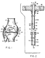
- Fig. 1 illustrates a knee joint 10 between the distal end 11 (i.e., that surface farthest from the center of the body) of a femur 12 and the proximal end 13 (i.e., that surface closest to the center of the body) of the tibia 14.
- Portions 15, 17 of the connective tissue which movably ties the femur 12 to the underlying tibia 14 and fibula 18 are shown.
- Normally interposed between opposing surfaces of the femur 12 and tibia 14 are lateral and medial meniscus cartilages, 21 and 23, respectively.
- the condyles 22 at the distal end 11 of the femur 12 are normally supported by the meniscus cartilages 21 and 23 on the proximal end 13 of the tibia 14.
- the distal end 11 of femur 12, including the condyles 22 is covered by a layer 28 of cartilaginous material about 5 mm thick, referred to as the articular cartilage.
- Articular cartilage 28 forms a generally resilient pad which is fixed on the distal surface 11 of the femur 12 to protect the femur from wear and mechanical shock.
- the articular cartilage 28 when lubricated by fluid in the knee joint 10, provides a surface which is readily slidable on the underlying surfaces of the meniscus cartilages 21 and 23 or on the proximal surface 13 of the tibia 14 if one or both of the meniscus cartilages 21, 23 should be partially or totally absent. Nevertheless, the articular cartilage 28 may become damaged in that it may be torn 24 or holed or become excessively worn.
- Another repair method involves packing an articular cartilage defect with bits of cancellous and cortical bone (Soviet Patent SU 1454423, June 27, 1986) that have been chipped from defect-free bone. This latter technique avoids using foreign materials but, like the former methods, does not preserve the original orientation of bone and cartilage.
- Prostheses have also been used for replacement of the joint itself. Problems encountered after implanting such prostheses are usually caused by the cements used to attach the prostheses to the host bone. Further, some prostheses associated with joint replacements are actually much larger than the degenerated tissue that needs to be replaced so that extensive portions of healthy bone are typically removed to accommodate the prostheses.
- US-A-3,848,601 and DE-U-9,312,792 are prior art documents to the present application.
- US-A-4,649,918 discloses a tool according to the preample of claim 1.
- the present invention is characterized by the features of the characterizing portion of claim 1.
- Optional features are recited in the dependent claims.
- the present invention is an apparatus for repairing articular cartilage defects, that harvest and utilize intact bone and intact articular cartilage plugs that preserve the natural orientation of the bone and articular cartilage.
- One embodiment of the invention is a bone plug removal tool that includes a cylindrical cutting element having an external surface and having an internal surface defining an internal bore extending along a longitudinal axis of the cutting element from a proximal cutting edge.
- a cutting tooth is engaged with the internal surface at the proximal cutting edge and extends into the internal bore.
- the tooth is substantially orthogonal to the longitudinal axis of the cutting element and is defined between orthogonally extending surfaces disposed in parallel.
- a replaceable outer cylindrical sheath is arranged concentrically around the external surface of the cylindrical cutting element.
- the sheath also has an internal surface defining an internal bore extending along a longitudinal axis of the sheath.
- the sheath has a proximal terminus that is spaced-apart from the proximal cutting edge of the cylindrical cutting element and the terminus is designed to engage a surface of the bone to define a depth stop for the cutting edge.
- the cutting tooth is a single tooth and screw threads are disposed on the external surface of the cylindrical cutting element for mating with corresponding screw threads on the internal surface of the cylindrical sheath.
- a handle may be engaged with a distal end of the tool for turning the tool into the bone once it has been driven to the desired depth.
- a bone plug remover having an elongated body including two concentric elements in which an inner element is a cutting element and an outer element is replaceable and defines a depth stop for cutting.
- the preferred emplacement tool includes a cylindrical element having an internal surface defining an internal bore extending along a longitudinal axis of the element from a proximal end. The internal surface further defines an internal step adjacent a distal end of the element.
- a stem is disposed for co-axial movement within the element, the stem having a proximal end disposed within the internal bore.
- a shoulder is defined in the stem for mating engagement with the internal distal step of the element in order to limit distal movement of the stem within the internal bore.
- the proximal end of the stem is spaced-apart from the proximal end of the coaxial element, the respective proximal ends defining between them an internal bone plug receiving space for receiving a bone plug of a certain length.
- the stem may be moved from a distal position, where the shoulder and step are engaged and the respective proximal ends define the space for receiving a bone plug, to a proximal position, where the stem is moved proximally within the internal bore and the bone plug is driven from the internal bone plug receiving space.
- a second step may be defined in the stem for limiting proximal movement. This second step is located distal to the first step and external to the cylindrical element. It is preferred that, in the distal position, the second step and the distal end of the element are at a distance from each other that is equal to, or less than, the length of the bone plug.
- a further embodiment is a kit incorporating the various tools.
- the kit for repair of an articular cartilage includes the bone plug removal tool of the invention, an elongated plunger for insertion into the proximal end of the cutting element and for coaxial movement within it, the plunger for displacing a bone plug from the distal end of the cutting element and the bone plug emplacement tool of the invention.
- Kits may also include a drill bit containing a depth stop for removing a portion of damaged articular cartilage.
- a further embodiment of the invention also includes the combination of the bone plug emplacement tool of the invention and an excised bone plug contained within the internal bone plug receiving space of the emplacement tool.
- the present invention is useful in methods of repairing a defective articular cartilage.
- Such methods may include the steps of removing a section of defective articular cartilage from a site of cartilage damage and forming a hole of sufficient depth to penetrate bone underlying the site of defective articular cartilage.
- a bone plug comprising intact bone and intact articular cartilage adhering thereto is removed from a bone lacking defective articular cartilage and is placed into the hole at the site of articular cartilage damage, so that the intact articular cartilage of the bone plug is co-extensive, and in lateral registration (i.e., aligned) with, articular cartilage external to the bone hole at the site of cartilage damage.
- the term "intact" in this context means that the bone and overlying articular cartilage undergo minimal physical disturbance during the removal process.
- the bone plug removal tool 30 is a substantially cylindrical device made out of two pieces of surgical stainless steel.
- the tool 30 is formed into a cylindrical cutting element 32 and a cylindrical sheath 48 that is arranged concentrically around the cylindrical cutting element 32.
- Cutting element 32 has an external surface 34 and an internal surface 36.
- the internal surface 36 further defines an internal bore 38 extending along a longitudinal axis 40 (arrows A-A) of the cylindrical cutting element 32.
- the bore 38 extends distally away from a proximal cutting edge 42.
- proximal refers to those portions of the apparatus that are closest to the center of the body or, alternately, are furthest away from the operator of the apparatus.
- distal refers to those portions of the apparatus that are furthest from the center of the body or, alternately, are closest to the operator of the apparatus.
- the internal bore 38 extends from the proximal cutting edge 42 to the distal end 43 of the cylindrical cutting element 32 from which a bone plug can be removed by the operator after bone plug extraction has been completed.
- the proximal cutting edge 42 is sharpened so that any bone entering the internal bore 38 is cut from the surrounding bone. An excised bone plug trapped within bore 38 can move freely into this space and out the distal end 43 after the plug excision procedure has been completed, as discussed in more detail below.
- At least one cutting tooth 44 is engaged with the internal surface 36 of the cylindrical cutting element 32 at the proximal cutting edge 42.
- This tooth 44 extends into the internal bore 38 in a direction that is substantially orthogonal to longitudinal axis 40 of the cylindrical cutting element 32.
- the cutting tooth 44 is defined by orthogonally extending tooth surfaces 46 that are disposed in parallel. Although a plurality of such teeth may be orthogonally disposed at the proximal cutting edge 42, in the most preferred embodiments of the present invention, only a single cutting tooth is necessary.
- the cutting tooth 44 is preferably rectangular or square in shape. It is also understood, however, the cutting tooth 44 may be generally triangular in shape as shown in Fig. 4B.
- the cutting tooth 44 moreover, preferably extends one-fifth of the diameter of the bore 38, although it may range from approximately 1/16 to 1/4 of the bore 38.
- the outer cylindrical sheath 48 is arranged concentrically around the external surface 34 of the cylindrical cutting element 32.
- the sheath has an internal surface 50 that also defines an internal bore 51 extending along longitudinal axis 52 of the sheath 48.
- the outer cylindrical sheath 48 is removably engaged with the cylindrical cutting element 32 by way of matching screw threads 56, 58 located on the internal surface 50 of the cylindrical sheath 48 and on the external surface 34 of cylindrical cutting element 32, respectively. Therefore, the outer cylindrical sheath 48 is removable and may be replaced by another outer sheath having different dimensions by mating the corresponding screw threads.
- outer cylindrical sheath 48 when engaged with the cylindrical cutting element 32, have a proximal terminus 54 that is not co-extensive with the proximal cutting edge 42 of the cutting element 32.
- the proximal terminus 54 of outer cylindrical sheath 48 is spaced apart from the proximal cutting edge 42 by a distance that defines a depth stop distance X.
- the depth stop distance X defines the length of the bone plug that is to be removed.
- an elongated, preferably cylindrical handle 60 may cooperate with the adjacent distal end 43 of the cutting element 32 by way of a second bore 62 that extends through the cutting element 32 orthogonally to the longitudinal axis 40 of the cylindrical cutting element 32.
- Handle 60 may be inserted after the tool has been driven to the desired depth and is used for rotating the tool to cause the bone to break at proximal cutting edge 42.
- handle 60 may be replaced by a conventional screw head (not shown) having a slot defined in it for receiving a screw driver or other, similar device.
- Handle 60 may also be replaced by a conventional hexagonal nut (not shown) which designed to receive a conventional socket wrench, socket driver or attached drill head.
- the cutting element 32 is preferably driven into the bone without any rotational movement, such as by hammering or tapping, it is also understood that the cutting element 32 may be screwed or twisted into the bone by means of a screwdriver, socket wrench or other similar device (not shown).
- corresponding threads 56, 58 may be replaced in other embodiments by conventional spring loaded snap-fit linkages (not shown).
- the exact nature of the handle and the nature of the removable coupling between the cylindrical cutting element and the outer cylindrical sheath is not intended to limit the scope of the invention in any way.
- the dimensions of the plug removal tool 30 may vary according to the surgical procedures. In preferred embodiments, however, the bone plug removal tool 30 is about 6 inches (152.4 mm) in overall length. If a handle is used, the handle 60 is about 4 inches (101.6 mm) in total length with a diameter of about .31 inches (7.9 mm).
- the outer cylindrical sheath 48 has an outside diameter of 0.30 inch (7.6 mm) to provide sufficient surface area to effectively limit the depth of penetration of the internal cylindrical cutting element 32.
- the distance between the respective proximal ends of the cylindrical sheath 48 and the cylindrical cutting element 32 will of necessity vary according to the depth of the bone plug. It is contemplated that this distance will vary between 5 mm and 15 mm.
- the outside diameter of the cylindrical cutting element 32 at the proximal cutting edge 42 may also vary but is most preferably about 0.25 inches (6.3 mm) with a bore of about 0.196 inches (4.9 mm) inside diameter.
- the bore will preferably range between 4.5 mm and 10 mm, it will again be appreciated that this inside diameter can be smaller or larger depending upon the circumstances.
- Fig. 5 illustrates a plunger 70 that is designed to accomplish this.
- Plunger 70 includes a shaft 72 having a proximal end 74 and a distal portion 76 whose outside diameter is significantly larger than the outside diameter of the rest of the shaft. The differences in outside diameter between the shaft 72 and the distal portion 76 form a step 77 at the junction of the distal portion 76 and shaft 72. The outside diameter of the shaft is sufficiently small so that shaft 72 can be passed between the cutting tooth 44 and the opposite, internal surface 36 of the cylindrical cutting element 32.
- An exemplary plunger that may be used with the bone plug removal tool has a shaft of about 0.125 inches (3.17 mm) in diameter and at length of about 7 inches (177.8 mm) between its proximal end 74 and the step 77.
- Figs. 6 and 7 illustrate a bone plug emplacement tool 80 used to drive an excised bone plug into a drilled bone hole so that defective articular cartilage may be repaired.
- Fig. 6 also shows a bone plug 78 in place within the emplacement tool 80.
- Bone plug emplacement tool 80 includes cylindrical element 82 having an internal surface 84 defining an internal bore 86.
- Element 82 has an expanded section 83 adjacent distal end 92.
- the internal bore 86 extends along a longitudinal axis 87 of the element 82 from a proximal end 88 of the element 82.
- Element 82 has a distal end 92.
- the internal surface 84 further defines, adjacent the distal end 92 of the element 82, an internal step 90.
- a stem 94 which may be solid, is disposed within the internal bore 86 and is adapted for co-axial (i.e. distal-proximal) movement.
- Stem 94 does not have an uniform outside diameter but includes a first shoulder 98 that is designed to mate in facing relationship to the internal step 90 of the cylindrical element 82.
- first shoulder 98 and internal step 90 are thus engaged, distal movement of the stem within the internal bore is halted.
- the proximal end 96 of stem 94 is located within internal bore 86 and is spaced apart from the proximal end 88 of the cylindrical element 80.
- the respective proximal ends 88, 96 define between them an internal bone plug receiving space that is configured to receive the bone plug 78 that is to be emplaced.
- the stem 94 extends distally from the distal end 92 of cylindrical element 82.
- the stem 94 has defined in it a second shoulder 100.
- the second shoulder 100 is designed to engage with the distal end 92 of element 82 and this engagement limits the proximal movement of the stem 94 within the internal bore 86.
- the distance (Z) between the second shoulder 100 and distal end 92 of the cylindrical element 82 is designed to be at least equal to the longest dimension of the bone plug 78.
- the distance (Z') between the proximal end 96 of stem 94 and the proximal end 88 of the cylindrical element 82 is also at least equal to the longest dimension of the bone plug 78 and equal in length to the length of the internal bone plug receiving space.
- the distance (Z) between the second shoulder 100 and the distal end 92 of the cylindrical element 82 is slightly less than the bone plug depth.
- Z is 4 mm; for a 10 mm long bone plug, distance Z is 9 mm; for a 15 mm bone plug, distance Z is 14 mm, and so on.
- the distance (Z') between the proximal end 96 of the stem 94 and the proximal end 88 of the cylindrical element 82 is also slightly less than the bone plug depth.
- the distance (Z') between the respective proximal ends 88, 96 is 4 millimeters so that one millimeter of bone will protrude from the proximal end 88 of the cylindrical element 82. This protruding section assists the operator in finding the drilled bone hole prior to emplacement.
- the stem 94 is adapted for movement from a distal position (Fig. 6), where the first shoulder 98 and the internal step 90 are engaged and the respective proximal ends 88, 96 define between them the internal bone plug receiving space.
- the stem 94 then moves to a proximal position (Fig. 7) where the second shoulder 100 engages with the distal end 92 of cylindrical element 82 and the bone plug is disgorged from within the internal bone plug receiving space, as described below.
- An exemplary emplacement tool that is compatible with the bone plug removal tool discussed previously has a cylindrical element that defines an internal bore of about 0.196 inches (4.9 mm) inside diameter.
- the outside diameter of the cylindrical element may be about 0.25 inches (6.3 mm) in diameter.
- the length of the cylindrical element from its proximal end to the beginning of the expanded section 83 may be about 5.5 inches (139.7 mm) in length.
- the surgical technique described herein is preferably performed arthroscopically using conventional equipment, although open techniques may be utilized should proper bone plug insertion prove impossible by arthroscopic means.
- a bone plug removal tool of the present invention is prepared.
- a standard anterolateral or medial or superior portal is used to introduce a 4.5 mm, 30° oblique arthroscope, and a shaver is applied through an anteromedial portal to prepare the articular cartilage defect. After shaving the degenerated cartilage in the vicinity of the defect, an 8 mm skin incision is made on the superolateral corner of the patellofemoral joint.
- the bone plug removal tool 30 is inserted through this portal and at least one cylindrical bone plug (5 mm in diameter and 10 mm in length) is taken from the lateral wall of the patellar groove, located outside the patellofemoral joint. A bone plug may also be taken from the anterolateral side of the intercondylar area. Three holes, each with a diameter of 4.8 mm, are then made using a drill bit through the anteromedial portal.
- the bone plug is removed from the removal tool 30 using the plunger 70 and positioned within the emplacement tool 80, as described below.
- the bone plug emplacement tool 80 of the invention containing the bone plug in its correct orientation is placed over the hole through this portal and the bone plug is pushed into the hole using the emplacement tool 80, as described herein.
- the present invention contemplates repairing a defect or damaged area 110 in an articular cartilage 112 by removing a conveniently shaped (for example circular) portion 114 of the defective articular cartilage layer 112 and a portion 115 of the underlying bone 116.
- Fig. 8A illustrates the general principle, discussed more fully below, that the surface area of the bone portion removed 115 is not necessarily co-extensive with the surface area 114 of cartilage removed.
- the edges 122 of the defect 110 are debrided to create vertical walls and sharp edges.
- the base of the defect is shaved smooth but is not abraded through to the subchondral bone.
- the size of the removed portion 114 is kept to a minimum but is large enough to include the whole of the damaged cartilage area.
- the bone is drilled with a hand or power drill containing a drill bit that most preferably has an expanded outside diameter (i.e., a depth stop countersink) located some distance distal to the proximal end of the drill bit.
- An exemplary drill bit used with the present methodology has a cutting surface exactly equal to the chosen length of the bone plug. That is, the cutting surface can be between about 5 mm and 15 mm in length.
- the outside diameter of such an exemplary drill bit is very slightly undersized relative to the inside bore diameter of the bone core removal tool. In particular, an internal bore of 0.196 (4.97 mm) inside diameter for the cylindrical cutting element of a bone core removal tool would require a drill bit of 0.190 (4.82 mm) inches outside diameter.
- the difference of 0.006 (0.15 mm) inches is necessary for the required interference fit of the bone plug within the drilled bone hole.
- the outside diameter of the drill bit begins its expanded depth stop section at a distance above the proximal end that is equal to the depth of the bone plug.
- This expanded section may be 0.25 inches (6.35 mm) in diameter and can be about 6 inches (152.4 mm) long.
- Bone holes drilled into the underlying bone may be of any depth but are most preferably about 5 mm to about 15 mm in depth. It is most preferred that excised plugs of articular cartilage with the underlying subchondral cancellous bone attached have a total length of about 10 mm. This will provide individual bone plugs having about 5 mm of cartilage and 5 mm of bone or other similar combinations such as 2mm of cartilage and 8 mm of bone, 3 mm of cartilage and 7 mm of bone, etc.
- each bone hole designed to receive a single bone plug (Fig. 8D) or a single bone hole may be drilled to receive a plurality of bone plugs (Fig. 9).
- a correspondingly sized and shaped bone plug 118 is inserted, first into and through the opening 114 left in the articular cartilage layer 112, and then into the underlying drilled bone hole 120.
- the bone plug 118 contains both bone 116A and its overlying articular cartilage 112A. These plugs will most preferably be taken from the non weight-bearing surfaces of the joint principally in the intracondylar notch and the periphery of the condyle.
- the bone plug 118 is inserted into the drilled bone hole 120 so that the articular cartilage layer 112A of bone plug 118 is in lateral registration with (i.e., is aligned with) the articular cartilage layer 112 surrounding the drilled bone hole 120.
- the bone plug 118 is of sufficient shape to maintain a frictional fit within the drilled bone hole 120 and will remain there until such time as tissue ingrowth from the surface of the bone and peripheral, cut edges 122 of the articular cartilage layer 112 surrounding the bone hole 120 more permanently fix the bone plug 118 in place.
- Bone plugs 118 may be positioned within a single bone hole 120 so that their respective outer peripheral edges are not in contact with each other. More preferably, individual bone plugs 118 located in their respective bone holes 120 may have their centers between 3 mm and 5 mm apart (See Fig. 8D).
- the peripheral edges 113, 115 of a given bone plug 118 are preferably positioned at some distance (Y) from the cut edges 122 of the defect and it is preferred that this distance be no further than about 5 mm.
- an articular cartilage defect 10 mm in diameter may accommodate one 5 mm diameter plug in the center of the defect.
- a defect 20 mm in diameter may be divided into four, 10 mm diameter quadrants and four holes drilled in the underlying bone. The defect therefore receives a total of four bone plugs.
- the bone plug 118 is designed to have a friction fit into the drilled bone hole 120
- several temporary fixation techniques are available.
- One such technique involves sewing sutures through the respective peripheral edges 113 of the articular cartilage layer 112A adhering to the bone plug and the articular cartilage 122 of the surrounding tissue.
- an adhesive layer (not shown) may be provided between the bone plug 118 and drilled bone hole 120. This adhesive layer allows time for sufficient ingrowth of tissue from the surrounding environment so that bone plug is locked into place in the bone hole.
- Various bio-adhesives are well known in the art. See for example U.S. Patent 5,067,964 (fibrinogen and thrombin sealant). Bone growth or cartilage growth promoting chemical factors may also be added.
- CDGF- cartilage-derived growth factor
- CSF colony-stimulating factor
- PDGF platelet-derived growth factor
- BMP-1 bone morphogenic protein
- the bone plug removal tool 30 is positioned above the bone/cartilage surface and the proximal cutting edge 40 of the cylindrical cutting element is preferably tapped with a hammer (not shown) to seat the proximal cutting edge 40.
- the handle 60 is turned a minimum of 360° degrees and the cylindrical cutting element 32 engages the bone down to a depth that is limited by contact of the proximal terminus of the outer sheath 54 with the bone surface.
- the outer sheath 54 does not cut into the bone.
- the tool 30 is then pulled distally away from the bone with a twisting action to remove the bone plug.
- the plunger 70 is then inserted through the proximal cutting edge 42 of the bone plug removal tool 30 to push or tap the bone plug through the internal bore 38 and out the distal end 43 of the bone plug removal tool 30.
- the excised bone plug is then manually inserted, typically by the surgeon, into the receiving space of the emplacement tool 80, articular cartilage surface 112A first. This insures proper orientation of the bone plug within the receiving space so that the excised articular cartilage layer 112A is engaged with the proximal end of the stem 96. It is particularly preferred that about one millimeter (1 mm) of underlying bone protrude from the proximal end 88 of the cylindrical element 82. This configuration allows the operator to find the drilled bone hole more easily.
- the bone plug is pressed into the drilled bone hole by moving the stem 94 from the distal to the proximal position so that the excised bone plug can be disgorged into the bone hole.
- the holes drilled in the donor defects are filled with collagen plugs.
- Post operative rehabilitation may include nonweight bearing for eight weeks with crutches. Full active motion of the knee will be encouraged such as "nonweight bearing” exercise with a stationary bike using minimal resistance but high speed. This is useful for thigh rehabilitation as soon as pain and swelling permits. Running and pivoting activities should not be allowed until after healing is confirmed either radiographically or by relook arthroscopy.
- Patients are selected with significant full thickness articular cartilage defects located on the weight bearing surface of the femur.
- patients are a minimum age of 14 years, have a thickness defect in the distal femoral condyle that includes those caused by osteochondritis dissecans and trauma that is at least 10 mm but no larger than 30 mm in diameter, adequate bone density, a willingness to comply with the study protocol, and a commitment to return for at least two years follow up.
- No patient with an active infection, who does not meet all of the inclusion criteria, or who has had prior knee surgery that would compromise the vascular supply is included.
- Preoperative assessment includes a history including any identifiable etiology of the defect, a physical and radiographic evaluation, and the completion of both the Lysholm knee scoring scale and Tegner activity level scale.
- the objective evaluation includes tests for mensical signs, range of motion, atrophy, effusion, instability (Lachman, anterior drawer, and pivot shift), and patellofemoral problems. Baseline radiographs are obtained. The findings at surgery and procedures performed are recorded.
- Post operative assessments occur at intervals of 1, 2, 3, 6, 12, and 24 months. These assessments are essentially the same as the preoperative evaluations and include the data for the Lysholm and Tegner scale and knee radiographs.
Landscapes
- Health & Medical Sciences (AREA)
- Life Sciences & Earth Sciences (AREA)
- Orthopedic Medicine & Surgery (AREA)
- Veterinary Medicine (AREA)
- Public Health (AREA)
- Biomedical Technology (AREA)
- Heart & Thoracic Surgery (AREA)
- Engineering & Computer Science (AREA)
- Surgery (AREA)
- Animal Behavior & Ethology (AREA)
- General Health & Medical Sciences (AREA)
- Oral & Maxillofacial Surgery (AREA)
- Transplantation (AREA)
- Molecular Biology (AREA)
- Medical Informatics (AREA)
- Nuclear Medicine, Radiotherapy & Molecular Imaging (AREA)
- Cardiology (AREA)
- Vascular Medicine (AREA)
- Dentistry (AREA)
- Physical Education & Sports Medicine (AREA)
- Rheumatology (AREA)
- Prostheses (AREA)
- Surgical Instruments (AREA)
- Materials For Medical Uses (AREA)
Claims (19)
- Chirurgisches System mit einem Werkzeug (30) zur Entnahme eines Knochenstopfens, bestehend aus:einem zylindrischen Schneidelement (32) mit einer Außenfläche (34) und einer Innenfläche (36), die eine Innenbohrung (38) bildet, welche sich entlang einer Längsachse des Schneidelements (32) von einem proximalen Ende zu einem distalen Ende (43) des Schneidelements (32) erstreckt; einer am proximalen Ende des Schneidelements (32) gelegenen Schneidkante (42) zum Ausschneiden eines Knochenstopfens beim Eintreiben des Schneidelements (32) in einen Knochen und zumindest einem Schneidzahn (44), der am proximalen Ende des Schneidelements (32) angeordnet ist und sich in die Innenbohrung in einer Richtung erstreckt, die im wesentlichen orthogonal zur Längsachse des Schneidelements verläuft, wobei das Werkzeug dadurch gekennzeichnet ist, daßder Schneidzahn (44) zwischen zwei im wesentlichen orthogonal verlaufenden Flächen verläuft, die im wesentlichen parallel zueinander angeordnet sind, eine äußere zylindrische Hülse (48) konzentrisch um die Außenfläche (34) des zylindrischen Schneidelements (32) angeordnet ist, die Hülse (48) eine Innenfläche (50) aufweist, die eine Innenbohrung (51) bildet, welche sich entlang einer Längsachse der Hülse (48) erstreckt, und die Hülse (48) einen proximalen Endpunkt aufweist, der von der Schneidkante (42) des zylindrischen Schneidelements (32) distal beabstandet ist.
- System nach Anspruch 1, bei dem der proximale Endpunkt (54) der Hülse (48) mit einer Oberfläche des Knochens in Eingriff bringbar ist und einen Tiefenanschlag für die Schneidkante (42) bildet.
- System nach Anspruch 1, bei dem der von dem Werkzeug ausgeschnittene Knochenstopfen eine Länge gleich dem Abstand zwischen dem proximalen Endpunkt (54) der zylindrischen Hülse (48) und der proximalen Schneidkante (42) des Schneidelements (32) aufweist.
- System nach Anspruch 1, bei dem der Schneidzahn (44) ein Einzelzahn ist.
- System nach Anspruch 1, bei dem der Schneidzahn eine (44) im wesentlichen rechteckige Form aufweist.
- System nach Anspruch 1, bei dem der Schneidzahn (44) eine im wesentlichen dreieckige Form aufweist.
- System nach Anspruch 1, bei dem der Schneidzahn (44) eine Erstrekkung von etwa einem Fünftel des Durchmessers der Innenbohrung (38) aufweist.
- System nach Anspruch 1, ferner mit einem Schraubgewinde (58) auf der Außenfläche (34) des zylindrischen Schneidelements (32) für einen Gewindeeingriff mit einem entsprechenden Gewinde (56) auf der Innenfläche (50) der zylindrischen Hülse (48).
- System nach Anspruch 1, ferner mit einem Handgriff (60) im Eingriff mit dem distalen Ende des Werkzeugs, wobei der Handgriff (60) mit dem Werkzeug in einer Richtung orthogonal zur Längsachse des Schneidelements (32) zum Hineindrehen des Werkzeugs in den Knochen zusammenwirkt.
- System nach Anspruch 1, ferner mit einem Schraubkopf oder einer Sechskantmutter in Eingriff mit dem distalen Ende des Werkzeugs zur Erleichterung des Hineindrehens des Werkzeugs in den Knochen.
- System nach Anspruch 1, ferner mit einem Werkzeug zur Einbettung eines Knochenstopfens, bestehend aus:einem zylindrischen Element (82) mit einer Innenfläche (84), die eine Innenbohrung (86) bildet, welche sich entlang einer Längsachse des Elements (82) von einem proximalen Ende desselben erstreckt, wobei die Innenfläche (84) ferner eine Innenstufe angrenzend an ein distales Ende des Elements (82) bildet; einem Dorn (94), der für eine koaxiale Bewegung im Element (82) angeordnet ist, wobei der Dorn (94) ein innerhalb der Innenbohrung angeordnetes proximales Ende aufweist; und einer ersten, im Dorn gebildeten Schulter (98) für einen zusammenwirkenden Eingriff mit der inneren distalen Stufe (90) des Elements (82) zur Begrenzung der distalen Bewegung des Dorns innerhalb der Innenbohrung (86), wobei das proximale Ende des Doms (94), an der Grenze der distalen Bewegung, vom proximalen Ende des zylindrischen Elements (82) beabstandet ist und das jeweilige proximale Ende des Dorns (94) und des Elements (82) zwischen sich einen inneren Aufnahmeraum für einen Knochenstopfen zur Aufnahme eines einzubettenden Knochenstopfens bilden, wobei der Dorn (94) aus einer distalen Stellung, in der die erste Schulter (98) und die Stufe (90) in Eingriff sind und das jeweilige proximale Ende des Dorns (94) und des Elements (82) zwischen sich einen Raum zur Aufnahme eines Knochenstopfens bilden, in eine proximale Stellung bewegbar ist, in der der Dorn (94) proximal in der Innenbohrung (86) bewegt und der Knochenstopfen aus dem inneren Aufnahmeraum für den Knochenstopfen herausgetrieben wird.
- System nach Anspruch 11, ferner mit einer zweiten, im Dorn (94) gebildeten Schulter (100) zur Begrenzung seiner proximalen Bewegung, wobei die zweite Schulter (100) distal zur ersten Schulter (98) und außerhalb des zylindrischen Elements (82) angeordnet ist und die zweite Schulter (100) einem Eingriff mit dem distalen Ende des zylindrischen Elements (82) dient, wenn sich der Dorn (94) in seiner proximalen Stellung befindet.
- System nach Anspruch 12, bei dem sich in der distalen Stellung die zweite Schulter (100) und das distale Ende des zylindrischen Elements (82) in einem Abstand voneinander befinden, der gleich der oder geringer als die Länge des Knochenstopfens ist.
- System nach Anspruch 1, ferner mit:(a) einem langgestreckten Stößel (70) zum Einsetzen in das proximale Ende des Schneidelements (32) zum Verschieben eines Knochenstopfens vom distalen Ende des Schneidelements und(b) einem Einbettungswerkzeug für einen Knochenstopfen, bestehend aus:einem zylindrischen Element (82) mit einer Innenfläche (84), die eine Innenbohrung (86) bildet, welche sich entlang einer Längsachse des Elements (82) von einem proximalen Ende desselben erstreckt, wobei die Innenfläche (84) ferner eine Innenstufe angrenzend an ein distales Ende des Elements (82) bildet; einem Dorn (94), der für eine koaxiale Bewegung im Element (82) angeordnet ist, wobei der Dorn (94) ein innerhalb der Innenbohrung angeordnetes proximales Ende aufweist; und einer ersten, im Dorn gebildeten Schulter (98) für einen zusammenwirkenden Eingriff mit der inneren distalen Stufe (90) des Elements (82) zur Begrenzung der distalen Bewegung des Doms innerhalb der Innenbohrung (86), wobei das proximale Ende des Doms (94), an der Grenze der distalen Bewegung, vom proximalen Ende des zylindrischen Elements (82) beabstandet ist und das jeweilige proximale Ende des Doms (94) und des Elements (82) zwischen sich einen inneren Aufnahmeraum für einen Knochenstopfen zur Aufnahme eines einzubettenden Knochenstopfens bilden, wobei der Dorn (94) aus einer distalen Stellung, in der die erste Schulter (98) und die Stufe (90) in Eingriff sind und das jeweilige proximale Ende des Doms (94) und des Elements (82) zwischen sich einen Raum zur Aufnahme eines Knochenstopfens bilden, in eine proximale Stellung bewegbar ist, in der der Dorn (94) proximal in der Innenbohrung (86) bewegt und der Knochenstopfen aus dem inneren Aufnahmeraum für den Knochenstopfen herausgetrieben wird.
- System nach Anspruch 14, ferner mit einem einen Tiefenanschlag umfassenden Bohrmeißel.
- System nach Anspruch 14, bei dem der proximale Endpunkt der Hülse des Entnahmewerkzeugs für den Knochenstopfen mit einer Oberfläche des Knochens in Eingriff bringbar ist und einen Tiefenanschlag für die Schneidkante bildet.
- System nach Anspruch 14, bei dem der von dem Knochenstopfen-Entnahmewerkzeug ausgeschnittene Knochenstopfen eine Länge gleich dem Abstand zwischen dem proximalen Endpunkt der zylindrischen Hülse (48) und der proximalen Schneidkante des Schneidelements (32) aufweist.
- System nach Anspruch 14, bei dem das Werkzeug zum Einbetten eines Knochenstopfens eine zweite, im Dorn (94) gebildete Schulter (100) zur Begrenzung seiner proximalen Bewegung aufweist, wobei die zweite Schulter (100) distal zur ersten Schulter und außerhalb des zylindrischen Elements (82) angeordnet ist und die zweite Schulter (100) einem Eingriff mit dem distalen Ende des zylindrischen Elements (82) dient, wenn sich der Dorn (94) in seiner proximalen Stellung befindet.
- System nach Anspruch 18, bei dem sich die zweite Schulter (100) und das distale Ende des zylindrischen Elements (82) des Werkzeugs zum Einbetten des Knochenstopfens in einem Abstand voneinander befinden, der gleich der oder geringer als die Länge des Knochenstopfens ist.
Applications Claiming Priority (3)
| Application Number | Priority Date | Filing Date | Title |
|---|---|---|---|
| US399428 | 1995-03-07 | ||
| US08/399,428 US5782835A (en) | 1995-03-07 | 1995-03-07 | Apparatus and methods for articular cartilage defect repair |
| PCT/US1996/001923 WO1996027333A1 (en) | 1995-03-07 | 1996-02-08 | Apparatus and methods for articular cartilage defect repair |
Publications (2)
| Publication Number | Publication Date |
|---|---|
| EP0814710A1 EP0814710A1 (de) | 1998-01-07 |
| EP0814710B1 true EP0814710B1 (de) | 2004-04-21 |
Family
ID=23579471
Family Applications (1)
| Application Number | Title | Priority Date | Filing Date |
|---|---|---|---|
| EP96905476A Expired - Lifetime EP0814710B1 (de) | 1995-03-07 | 1996-02-08 | Vorrichtung zur wiederherstellung von gelenkknorpeldefekten |
Country Status (6)
| Country | Link |
|---|---|
| US (2) | US5782835A (de) |
| EP (1) | EP0814710B1 (de) |
| JP (1) | JPH11501239A (de) |
| AU (1) | AU712301B2 (de) |
| DE (1) | DE69632247T2 (de) |
| WO (1) | WO1996027333A1 (de) |
Cited By (1)
| Publication number | Priority date | Publication date | Assignee | Title |
|---|---|---|---|---|
| US8753406B2 (en) | 2010-08-31 | 2014-06-17 | Zimmer Inc. | Osteochondral graft delivery device and uses thereof |
Families Citing this family (200)
| Publication number | Priority date | Publication date | Assignee | Title |
|---|---|---|---|---|
| US6716216B1 (en) * | 1998-08-14 | 2004-04-06 | Kyphon Inc. | Systems and methods for treating vertebral bodies |
| US6241734B1 (en) * | 1998-08-14 | 2001-06-05 | Kyphon, Inc. | Systems and methods for placing materials into bone |
| EP1058515A2 (de) * | 1996-09-17 | 2000-12-13 | Medicinelodge, Inc. | Anordnung und verfahren zur verankerung einer chirurgischen naht |
| US6007496A (en) * | 1996-12-30 | 1999-12-28 | Brannon; James K. | Syringe assembly for harvesting bone |
| US6146385A (en) * | 1997-02-11 | 2000-11-14 | Smith & Nephew, Inc. | Repairing cartilage |
| DE19708703C2 (de) * | 1997-02-24 | 2002-01-24 | Co Don Ag | Chirurgisches Besteck |
| US6761726B1 (en) * | 1998-05-15 | 2004-07-13 | Pyng Medical Corp. | Method and apparatus for the intraosseous introduction of a device such as an infusion tube |
| US7347840B2 (en) * | 2000-03-02 | 2008-03-25 | Pyng Medical Corp. | Patch for locating a target zone for penetration |
| EP0896825B1 (de) | 1997-08-14 | 2002-07-17 | Sulzer Innotec Ag | Zusammensetzung und Vorrichtung zur Reparatur von Knorpelgewebe in vivo bestehend aus Nanokapseln mit osteoinduktiven und/oder chondroinduktiven Faktoren |
| JP2001520911A (ja) * | 1997-10-27 | 2001-11-06 | ズルツァー オーソピーディクス リミテッド | 軟骨内および骨軟骨の欠損症を修復するための方法および器具 |
| US6395011B1 (en) | 1998-07-17 | 2002-05-28 | Johnson & Johnson | Method and apparatus for harvesting and implanting bone plugs |
| DE50009320D1 (de) | 1999-03-23 | 2005-03-03 | Zimmer Gmbh Winterthur | Instrument und Instrumentensatz zum Einbringen eines osteochondralen Transplantats |
| EP1038509B1 (de) * | 1999-03-23 | 2005-01-26 | Zimmer GmbH | Instrument und Instrumentensatz zum Einbringen eines osteochondralen Transplantats |
| USD447565S1 (en) | 1999-09-17 | 2001-09-04 | Genzyme Corporation | Straight medical device for the application of a tack to the body of a patient |
| US6322563B1 (en) | 1999-09-17 | 2001-11-27 | Genzyme Corporation | Small tissue and membrane fixation apparatus and methods for use thereof |
| USD443058S1 (en) | 1999-09-17 | 2001-05-29 | Genzyme Corporation | Curved medical device for the application of a tack to the body of a patient |
| EP1099443A1 (de) | 1999-11-11 | 2001-05-16 | Sulzer Orthopedics Ltd. | Transplantations/Implantatsvorrichtung und ihre Herstellungsmethode |
| CA2638625C (en) * | 1999-12-03 | 2012-07-24 | University Of Leeds | Fixation technology for bone repair |
| US6858042B2 (en) | 1999-12-15 | 2005-02-22 | Zimmer Orthobiologics, Inc. | Preparation for repairing cartilage defects or cartilage/bone defects in human or animal joints |
| US6626945B2 (en) * | 2000-03-14 | 2003-09-30 | Chondrosite, Llc | Cartilage repair plug |
| US6375658B1 (en) | 2000-04-28 | 2002-04-23 | Smith & Nephew, Inc. | Cartilage grafting |
| US20040230315A1 (en) * | 2000-05-01 | 2004-11-18 | Ek Steven W. | Articular surface implant |
| US6610067B2 (en) | 2000-05-01 | 2003-08-26 | Arthrosurface, Incorporated | System and method for joint resurface repair |
| US7618462B2 (en) * | 2000-05-01 | 2009-11-17 | Arthrosurface Incorporated | System and method for joint resurface repair |
| US7713305B2 (en) * | 2000-05-01 | 2010-05-11 | Arthrosurface, Inc. | Articular surface implant |
| US6679917B2 (en) | 2000-05-01 | 2004-01-20 | Arthrosurface, Incorporated | System and method for joint resurface repair |
| US7163541B2 (en) | 2002-12-03 | 2007-01-16 | Arthrosurface Incorporated | Tibial resurfacing system |
| US8177841B2 (en) | 2000-05-01 | 2012-05-15 | Arthrosurface Inc. | System and method for joint resurface repair |
| US7678151B2 (en) * | 2000-05-01 | 2010-03-16 | Ek Steven W | System and method for joint resurface repair |
| EP2314257B9 (de) | 2000-05-01 | 2013-02-27 | ArthroSurface, Inc. | System zur Gelenkoberflächenerneuerung |
| ES2324282T3 (es) | 2000-05-01 | 2009-08-04 | Arthro Surface, Inc. | Sistema de reparacion de la superficie de una articulacion. |
| AU2005202099B2 (en) * | 2000-05-01 | 2007-06-07 | Arthrosurface, Incorporated | System and method for joint resurface repair |
| US6488033B1 (en) * | 2000-05-15 | 2002-12-03 | Cryolife, Inc. | Osteochondral transplant techniques |
| KR20030029621A (ko) * | 2000-07-14 | 2003-04-14 | 카이폰 인코포레이티드 | 척추체의 치료 시스템 및 방법 |
| US6638312B2 (en) | 2000-08-04 | 2003-10-28 | Depuy Orthopaedics, Inc. | Reinforced small intestinal submucosa (SIS) |
| US8366787B2 (en) | 2000-08-04 | 2013-02-05 | Depuy Products, Inc. | Hybrid biologic-synthetic bioabsorbable scaffolds |
| US6517579B1 (en) * | 2000-09-06 | 2003-02-11 | Lonnie E. Paulos | Method and apparatus for securing a soft tissue graft to bone during an ACL reconstruction |
| DE10048575A1 (de) * | 2000-09-30 | 2002-04-11 | Coripharm Medizinprodukte Gmbh | Chirurgisches Werkzeug |
| ATE499908T1 (de) | 2001-07-16 | 2011-03-15 | Depuy Products Inc | Gerät zur reparatur von knorpelmaterial |
| JP4197160B2 (ja) * | 2001-07-16 | 2008-12-17 | デピュイ・プロダクツ・インコーポレイテッド | 軟骨修復および再生用の支持骨格材料および方法 |
| JP4294474B2 (ja) | 2001-07-16 | 2009-07-15 | デピュイ・プロダクツ・インコーポレイテッド | 半月板再生装置 |
| AU2002316694B2 (en) * | 2001-07-16 | 2007-09-06 | Depuy Products, Inc. | Hybrid biologic/synthetic porous extracellular matrix scaffolds |
| AU2002354913B2 (en) * | 2001-07-16 | 2008-07-17 | Depuy Products, Inc. | Unitary surgical device and method |
| JP4197158B2 (ja) | 2001-07-16 | 2008-12-17 | デピュイ・プロダクツ・インコーポレイテッド | 天然に発生する生物学的に誘導されている材料による装置 |
| US8025896B2 (en) | 2001-07-16 | 2011-09-27 | Depuy Products, Inc. | Porous extracellular matrix scaffold and method |
| US7201917B2 (en) * | 2001-07-16 | 2007-04-10 | Depuy Products, Inc. | Porous delivery scaffold and method |
| US7819918B2 (en) * | 2001-07-16 | 2010-10-26 | Depuy Products, Inc. | Implantable tissue repair device |
| US20030185892A1 (en) * | 2001-08-17 | 2003-10-02 | Bell Steve J. D. | Intraocular delivery compositions and methods |
| US20030055316A1 (en) * | 2001-09-19 | 2003-03-20 | Brannon James Kevin | Endoscopic bone debridement |
| KR100428933B1 (ko) * | 2001-10-11 | 2004-04-29 | 주식회사 덴티움 | 골 채취용구 |
| US7819888B2 (en) * | 2001-10-23 | 2010-10-26 | Innovasive Devices, Inc. | Method and apparatus for harvesting and implanting bone plugs |
| RU2218113C2 (ru) * | 2002-01-14 | 2003-12-10 | Государственный научно-клинический центр охраны здоровья шахтеров | Устройство для взятия цилиндрических костно-хрящевых трансплантатов |
| BR0307033A (pt) * | 2002-01-22 | 2004-12-07 | Pfizer | ácidos 3-(imidazolil)-2-aminopropanóicos para o uso como inibidores tafi-a para o tratamento de doenças trombóticas |
| US7811260B2 (en) * | 2002-05-31 | 2010-10-12 | Vidacare Corporation | Apparatus and method to inject fluids into bone marrow and other target sites |
| US9545243B2 (en) | 2002-05-31 | 2017-01-17 | Vidacare LLC | Bone marrow aspiration devices and related methods |
| JP4938979B2 (ja) | 2002-05-31 | 2012-05-23 | ヴァイダケア、コーパレイシャン | 骨髄にアクセスする装置および方法 |
| US20070049945A1 (en) | 2002-05-31 | 2007-03-01 | Miller Larry J | Apparatus and methods to install, support and/or monitor performance of intraosseous devices |
| US11337728B2 (en) | 2002-05-31 | 2022-05-24 | Teleflex Life Sciences Limited | Powered drivers, intraosseous devices and methods to access bone marrow |
| US8641715B2 (en) | 2002-05-31 | 2014-02-04 | Vidacare Corporation | Manual intraosseous device |
| US9314228B2 (en) | 2002-05-31 | 2016-04-19 | Vidacare LLC | Apparatus and method for accessing the bone marrow |
| US10973545B2 (en) | 2002-05-31 | 2021-04-13 | Teleflex Life Sciences Limited | Powered drivers, intraosseous devices and methods to access bone marrow |
| US8142365B2 (en) * | 2002-05-31 | 2012-03-27 | Vidacare Corporation | Apparatus and method for accessing the bone marrow of the sternum |
| US8668698B2 (en) | 2002-05-31 | 2014-03-11 | Vidacare Corporation | Assembly for coupling powered driver with intraosseous device |
| WO2008033873A2 (en) | 2006-09-12 | 2008-03-20 | Vidacare Corporation | Medical procedures trays and related methods |
| US8690791B2 (en) | 2002-05-31 | 2014-04-08 | Vidacare Corporation | Apparatus and method to access the bone marrow |
| US9072543B2 (en) | 2002-05-31 | 2015-07-07 | Vidacare LLC | Vascular access kits and methods |
| US11298202B2 (en) | 2002-05-31 | 2022-04-12 | Teleflex Life Sciences Limited | Biopsy devices and related methods |
| US10973532B2 (en) | 2002-05-31 | 2021-04-13 | Teleflex Life Sciences Limited | Powered drivers, intraosseous devices and methods to access bone marrow |
| US7951089B2 (en) * | 2002-05-31 | 2011-05-31 | Vidacare Corporation | Apparatus and methods to harvest bone and bone marrow |
| US9451968B2 (en) * | 2002-05-31 | 2016-09-27 | Vidacare LLC | Powered drivers, intraosseous devices and methods to access bone marrow |
| WO2008033871A2 (en) * | 2006-09-12 | 2008-03-20 | Vidacare Corporation | Apparatus and methods for biopsy and aspiration of bone marrow |
| DE10225217A1 (de) | 2002-06-06 | 2003-12-18 | Klaus Draenert | Implantat und Anordnung zum insbesondere partiellen Ersatz von belasteten Flächen |
| US6955678B2 (en) * | 2002-06-28 | 2005-10-18 | Smith & Nephew, Inc. | Soft tissue repair tool |
| US20040166169A1 (en) * | 2002-07-15 | 2004-08-26 | Prasanna Malaviya | Porous extracellular matrix scaffold and method |
| US7591820B2 (en) * | 2002-08-09 | 2009-09-22 | Arthrex, Inc. | Retrograde osteochondral autograft transfer system |
| US6951562B2 (en) * | 2002-11-13 | 2005-10-04 | Ralph Fritz Zwirnmann | Adjustable length tap and method for drilling and tapping a bore in bone |
| US7914545B2 (en) | 2002-12-03 | 2011-03-29 | Arthrosurface, Inc | System and method for retrograde procedure |
| US7901408B2 (en) * | 2002-12-03 | 2011-03-08 | Arthrosurface, Inc. | System and method for retrograde procedure |
| US20070043376A1 (en) | 2003-02-21 | 2007-02-22 | Osteobiologics, Inc. | Bone and cartilage implant delivery device |
| CA2516662A1 (en) * | 2003-02-21 | 2004-09-10 | Osteobiologics, Inc. | Bone and cartilage implant delivery device |
| US8388624B2 (en) | 2003-02-24 | 2013-03-05 | Arthrosurface Incorporated | Trochlear resurfacing system and method |
| AU2004216551B2 (en) * | 2003-02-26 | 2008-09-18 | Zimmer Orthobiologics, Inc. | Preparation for repairing cartilage tissue, especially articular cartilage defects |
| US7794408B2 (en) * | 2003-03-28 | 2010-09-14 | Ethicon, Inc. | Tissue collection device and methods |
| US20050222687A1 (en) * | 2004-04-02 | 2005-10-06 | Gordana Vunjak-Novakovic | Cartilage implant assembly and method for implantation |
| US20050064042A1 (en) * | 2003-04-29 | 2005-03-24 | Musculoskeletal Transplant Foundation | Cartilage implant plug with fibrin glue and method for implantation |
| US7067123B2 (en) | 2003-04-29 | 2006-06-27 | Musculoskeletal Transplant Foundation | Glue for cartilage repair |
| US20090291112A1 (en) * | 2003-05-16 | 2009-11-26 | Truncale Katherine G | Allograft osteochondral plug combined with cartilage particle mixture |
| US7901457B2 (en) | 2003-05-16 | 2011-03-08 | Musculoskeletal Transplant Foundation | Cartilage allograft plug |
| US7488348B2 (en) * | 2003-05-16 | 2009-02-10 | Musculoskeletal Transplant Foundation | Cartilage allograft plug |
| US9504477B2 (en) | 2003-05-30 | 2016-11-29 | Vidacare LLC | Powered driver |
| US8187336B2 (en) * | 2003-06-16 | 2012-05-29 | Jamali Amir A | Device and method for reconstruction of osseous skeletal defects |
| US8034003B2 (en) | 2003-09-11 | 2011-10-11 | Depuy Mitek, Inc. | Tissue extraction and collection device |
| US7611473B2 (en) | 2003-09-11 | 2009-11-03 | Ethicon, Inc. | Tissue extraction and maceration device |
| US8162967B1 (en) | 2003-10-16 | 2012-04-24 | Biomet Sports Medicine Llc | Method and apparatus for coring and reaming of bone |
| GB0325277D0 (en) * | 2003-10-28 | 2003-12-03 | Xiros Plc | Surgical instruments for use in the implantation of tissue repair kit |
| US7951163B2 (en) | 2003-11-20 | 2011-05-31 | Arthrosurface, Inc. | Retrograde excision system and apparatus |
| WO2005051231A2 (en) | 2003-11-20 | 2005-06-09 | Arthrosurface, Inc. | Retrograde delivery of resurfacing devices |
| EP2335650B1 (de) | 2003-12-11 | 2012-10-03 | Isto Technologies Inc. | Teilchenförmiges Knorpelsystem |
| US7815642B2 (en) * | 2004-01-26 | 2010-10-19 | Vidacare Corporation | Impact-driven intraosseous needle |
| ATE478606T1 (de) | 2004-01-26 | 2010-09-15 | Vidacare Corp | Manuelle interossäre vorrichtung |
| US7163542B2 (en) * | 2004-03-30 | 2007-01-16 | Synthes (U.S.A.) | Adjustable depth drill bit |
| US20050249772A1 (en) * | 2004-05-04 | 2005-11-10 | Prasanna Malaviya | Hybrid biologic-synthetic bioabsorbable scaffolds |
| US7569233B2 (en) * | 2004-05-04 | 2009-08-04 | Depuy Products, Inc. | Hybrid biologic-synthetic bioabsorbable scaffolds |
| DE102004028429B3 (de) * | 2004-06-03 | 2005-11-03 | Karl Storz Gmbh & Co. Kg | Vorrichtung zum Ausstanzen von Gewebebereichen an Knochen |
| JP2008504107A (ja) | 2004-06-28 | 2008-02-14 | アースロサーフィス・インコーポレーテッド | 関節面交換用システム |
| JP4429106B2 (ja) * | 2004-07-28 | 2010-03-10 | 大日本スクリーン製造株式会社 | 基板エッチング装置 |
| US20090149893A1 (en) * | 2007-12-05 | 2009-06-11 | Semler Eric J | Cancellous Bone Implant for Cartilage Repair |
| US20080220044A1 (en) * | 2007-03-06 | 2008-09-11 | Semler Eric J | Cancellous construct with support ring for repair of osteochondral defects |
| US7837740B2 (en) | 2007-01-24 | 2010-11-23 | Musculoskeletal Transplant Foundation | Two piece cancellous construct for cartilage repair |
| US7513866B2 (en) * | 2004-10-29 | 2009-04-07 | Depuy Products, Inc. | Intestine processing device and associated method |
| US8998848B2 (en) * | 2004-11-12 | 2015-04-07 | Vidacare LLC | Intraosseous device and methods for accessing bone marrow in the sternum and other target areas |
| US7828853B2 (en) | 2004-11-22 | 2010-11-09 | Arthrosurface, Inc. | Articular surface implant and delivery system |
| US7354627B2 (en) * | 2004-12-22 | 2008-04-08 | Depuy Products, Inc. | Method for organizing the assembly of collagen fibers and compositions formed therefrom |
| AU2006210847A1 (en) * | 2005-02-01 | 2006-08-10 | Osteobiologics, Inc. | Method and device for selective addition of a bioactive agent to a multi-phase implant |
| US8672941B2 (en) * | 2005-02-02 | 2014-03-18 | Kensey Nash Bvf Technology Llc | Coring device for preserving living tissue |
| JP4025827B2 (ja) * | 2005-02-10 | 2007-12-26 | フジコピアン株式会社 | 転写式感圧接着テープ |
| US8273088B2 (en) * | 2005-07-08 | 2012-09-25 | Depuy Spine, Inc. | Bone removal tool |
| US7815926B2 (en) | 2005-07-11 | 2010-10-19 | Musculoskeletal Transplant Foundation | Implant for articular cartilage repair |
| JP2007029566A (ja) * | 2005-07-28 | 2007-02-08 | Koji Hasegawa | 固定用ねじ及び固定用ねじの抜去用具 |
| US7595062B2 (en) | 2005-07-28 | 2009-09-29 | Depuy Products, Inc. | Joint resurfacing orthopaedic implant and associated method |
| WO2007025290A2 (en) | 2005-08-26 | 2007-03-01 | Isto Technologies, Inc. | Implants and methods for repair, replacement and treatment of joint disease |
| CA2623106C (en) | 2005-09-19 | 2013-12-24 | Histogenics Corporation | Cell-support matrix having narrowly defined uniformly vertically and non-randomly organized porosity and pore density and a method for preparation thereof |
| EP1764117A1 (de) | 2005-09-20 | 2007-03-21 | Zimmer GmbH | Implantat zur Wiederherstellung von Knorpeldefekten und Verfahren zu seiner Herstellung |
| US7371260B2 (en) * | 2005-10-26 | 2008-05-13 | Biomet Sports Medicine, Inc. | Method and instrumentation for the preparation and transplantation of osteochondral allografts |
| US8394100B2 (en) * | 2005-12-23 | 2013-03-12 | Warsaw Orthopedic, Inc. | Surgical apparatus and method for manipulating one or more osteochondral plugs |
| US7497861B2 (en) * | 2006-01-30 | 2009-03-03 | Warsaw Orthopedic, Inc. | Chisel system for osteochondral implants and a surgical procedure involving same |
| US8221423B2 (en) * | 2006-03-28 | 2012-07-17 | Warsaw Orthopedic, Inc. | Osteochondral plug graft harvesting instrument and kit |
| US20070270955A1 (en) * | 2006-04-10 | 2007-11-22 | Chow James C | Arthoscopic arthroplasty procedure for the repair or reconstruction of arthritic joints |
| US20070276506A1 (en) * | 2006-05-25 | 2007-11-29 | Biomet Manufacturing Corp. | Demineralized osteochondral plug |
| US20080058673A1 (en) * | 2006-08-29 | 2008-03-06 | Lex Jansen | Tissue extraction device and method of using the same |
| EP3659520B1 (de) | 2006-09-12 | 2023-11-08 | Teleflex Life Sciences Limited | Knochenmark-absaugvorrichtungen |
| US8944069B2 (en) | 2006-09-12 | 2015-02-03 | Vidacare Corporation | Assemblies for coupling intraosseous (IO) devices to powered drivers |
| US7879040B2 (en) * | 2006-10-23 | 2011-02-01 | Warsaw Orthopedic, IN | Method and apparatus for osteochondral autograft transplantation |
| US8974410B2 (en) | 2006-10-30 | 2015-03-10 | Vidacare LLC | Apparatus and methods to communicate fluids and/or support intraosseous devices |
| US7758583B2 (en) * | 2006-10-31 | 2010-07-20 | Warsaw Orthopedic, Inc. | Surgical instrument and method of use for facilitating positioning of an osteochondral plug |
| US7871440B2 (en) * | 2006-12-11 | 2011-01-18 | Depuy Products, Inc. | Unitary surgical device and method |
| AU2007332787A1 (en) | 2006-12-11 | 2008-06-19 | Arthrosurface Incorporated | Retrograde resection apparatus and method |
| US8163549B2 (en) | 2006-12-20 | 2012-04-24 | Zimmer Orthobiologics, Inc. | Method of obtaining viable small tissue particles and use for tissue repair |
| WO2008101097A2 (en) * | 2007-02-14 | 2008-08-21 | Arthrosurface Incorporated | Bone cement delivery device |
| US8118814B2 (en) | 2007-02-14 | 2012-02-21 | Depuy Mitek Inc. | Implement for orientating a tool, particularly useful in surgical tools for harvesting and implanting bone plugs to repair damaged bone tissue |
| US8435551B2 (en) | 2007-03-06 | 2013-05-07 | Musculoskeletal Transplant Foundation | Cancellous construct with support ring for repair of osteochondral defects |
| EP2134297B1 (de) | 2007-04-12 | 2017-03-08 | Zimmer, Inc. | Vorrichtung zur gewebereparatur |
| US20090054906A1 (en) * | 2007-08-24 | 2009-02-26 | Zimmer Orthobiologics, Inc. | Medical device and method for delivering an implant to an anatomical site |
| US8303592B2 (en) * | 2007-10-05 | 2012-11-06 | Biomet Manufacturing Corp. | System for forming a tendon-bone graft |
| US8322256B2 (en) * | 2007-10-05 | 2012-12-04 | Biomet Manufacturing Corp. | System for forming a tendon-bone graft |
| US8998918B2 (en) * | 2008-02-12 | 2015-04-07 | Amir Jamali | Device and method for allograft and tissue engineered osteochondral graft surface matching, preparation, and implantation |
| US8439921B2 (en) * | 2008-02-12 | 2013-05-14 | Amir Jamali | Device and method for allograft total hip arthroplasty |
| WO2009111481A1 (en) | 2008-03-03 | 2009-09-11 | Arthrosurface Incorporated | Bone resurfacing system and method |
| CA2717725A1 (en) | 2008-03-05 | 2009-09-11 | Musculoskeletal Transplant Foundation | Cancellous constructs, cartilage particles and combinations of cancellous constructs and cartilage particles |
| US8043375B2 (en) * | 2008-03-06 | 2011-10-25 | MoiRai Orthopaedic, LLC | Cartilage implants |
| US8801725B2 (en) | 2008-03-10 | 2014-08-12 | Zimmer Orthobiologics, Inc. | Instruments and methods used when repairing a defect on a tissue surface |
| US9020577B2 (en) * | 2008-05-29 | 2015-04-28 | Yale University | Systems, devices and methods for cartilage and bone grafting |
| US8012217B2 (en) * | 2008-07-03 | 2011-09-06 | Fellowship of Orthopaedic Researchers, LLC | Talar implants and methods of use |
| KR200453097Y1 (ko) * | 2009-04-02 | 2011-04-05 | 이달호 | 상악 잔골 최종 천공 겸용 상악동막 분리기 |
| US20100256758A1 (en) * | 2009-04-02 | 2010-10-07 | Synvasive Technology, Inc. | Monolithic orthopedic implant with an articular finished surface |
| US8556972B2 (en) * | 2009-04-02 | 2013-10-15 | Sevika Holding AG | Monolithic orthopedic implant with an articular finished surface |
| US10945743B2 (en) | 2009-04-17 | 2021-03-16 | Arthrosurface Incorporated | Glenoid repair system and methods of use thereof |
| CA3064646C (en) | 2009-04-17 | 2023-01-03 | Arthrosurface Incorporated | Glenoid resurfacing system and method |
| WO2010121250A1 (en) | 2009-04-17 | 2010-10-21 | Arthrosurface Incorporated | Glenoid resurfacing system and method |
| WO2011008968A1 (en) * | 2009-07-15 | 2011-01-20 | Yale University | Instruments, methods and systems for harvesting and implanting cartilage materials |
| US8419739B2 (en) * | 2009-08-24 | 2013-04-16 | Amir A. Jamali | Method and apparatus for allograft disc transplantation |
| AU2010286660B2 (en) | 2009-08-25 | 2015-07-16 | Fellowship Of Orthopaedic Researchers, Inc. | Trochlear implants and methods of use |
| BR112012022482A2 (pt) | 2010-03-05 | 2016-07-19 | Arthrosurface Inc | sistema e método de recomposição da superfície tibial. |
| AT509761B1 (de) * | 2010-04-29 | 2012-10-15 | Mario Dr Wieser | Knochenbiopsiefräser |
| US8690956B2 (en) | 2010-08-23 | 2014-04-08 | Fellowship Of Orthopaedic Researchers, Inc. | Talar implants and methods of use |
| US8801716B2 (en) * | 2010-08-24 | 2014-08-12 | Biomet Manufacturing, Llc | Cartilage repair system with flexible trephine |
| US9113916B2 (en) | 2010-08-31 | 2015-08-25 | Zimmer, Inc. | Drill bit for osteochondral drilling with guiding element and uses thereof |
| US8641718B2 (en) | 2010-10-19 | 2014-02-04 | Biomet Manufacturing, Llc | Method and apparatus for harvesting cartilage for treatment of a cartilage defect |
| JP5769334B2 (ja) | 2011-02-04 | 2015-08-26 | 国立大学法人佐賀大学 | 移植用ガイドおよび移植用器具 |
| US9066716B2 (en) | 2011-03-30 | 2015-06-30 | Arthrosurface Incorporated | Suture coil and suture sheath for tissue repair |
| ES2564513T3 (es) | 2011-12-03 | 2016-03-23 | Ouroboros Medical Inc. | Cabezales de corte seguros y sistemas para retirada rápida de un tejido diana |
| EP2804565B1 (de) | 2011-12-22 | 2018-03-07 | Arthrosurface Incorporated | System zur knochenfixierung |
| WO2013109708A1 (en) * | 2012-01-20 | 2013-07-25 | Accelerated Orthopedic Technologies, Inc. | Instruments, methods and systems for harvesting and implanting graft materials |
| BR112014027054B1 (pt) | 2012-04-30 | 2022-05-03 | The Johns Hopkins University | Dispositivo para coleta óssea |
| DE112013003358T5 (de) | 2012-07-03 | 2015-03-19 | Arthrosurface, Inc. | System und Verfahren für Gelenkoberflächenersatz und -reparatur |
| WO2014072982A2 (en) * | 2012-11-12 | 2014-05-15 | Cartiheal (2009) Ltd. | Tools and systems for solid form and graft implantation |
| US20140178343A1 (en) | 2012-12-21 | 2014-06-26 | Jian Q. Yao | Supports and methods for promoting integration of cartilage tissue explants |
| RU2508060C1 (ru) * | 2012-12-25 | 2014-02-27 | Федеральное государственное бюджетное учреждение "Центральный научно-исследовательский институт травматологии и ортопедии имени Н.Н. Приорова" Министерства здравоохранения Российской Федерации (ФГБУ "ЦИТО им. Н.Н. Приорова" Минздрава России) | Способ хирургического лечения остеохондральных поражений блока таранной кости методом мозаичной аутохондропластики |
| EP2967878B1 (de) | 2013-03-15 | 2020-02-26 | Think Surgical, Inc. | System zur erstellung eindeutiger muster in knochen für knorpelersatz |
| US9492200B2 (en) | 2013-04-16 | 2016-11-15 | Arthrosurface Incorporated | Suture system and method |
| DE102013007884B4 (de) * | 2013-05-08 | 2015-03-26 | Adalbert Missalla | Vorrichtung für das Einbringen einer ringspaltförmigen Sacklochbohrung in die Femurkondyle des menschlichen Körpers sowie für die Gewinnung des erzeugten zylindrischen Bohrkerns als Knochendübel |
| US10342563B2 (en) | 2013-07-19 | 2019-07-09 | DePuy Synthes Products, Inc. | Anti-clogging device for a vacuum-assisted, tissue removal system |
| US10624748B2 (en) | 2014-03-07 | 2020-04-21 | Arthrosurface Incorporated | System and method for repairing articular surfaces |
| US9931219B2 (en) | 2014-03-07 | 2018-04-03 | Arthrosurface Incorporated | Implant and anchor assembly |
| US11607319B2 (en) | 2014-03-07 | 2023-03-21 | Arthrosurface Incorporated | System and method for repairing articular surfaces |
| US9925068B2 (en) | 2014-05-30 | 2018-03-27 | Treace Medical Concepts, Inc. | Bone harvester and bone marrow removal system and method |
| US10077420B2 (en) | 2014-12-02 | 2018-09-18 | Histogenics Corporation | Cell and tissue culture container |
| CN104997552B (zh) * | 2015-04-27 | 2019-01-04 | 苏州同心医疗器械有限公司 | 一种外科开孔刀及其使用方法 |
| JP2018110602A (ja) * | 2015-05-21 | 2018-07-19 | テルモ株式会社 | インプラント部材組み合わせ体及びその使用方法 |
| CN106037877B (zh) | 2016-08-19 | 2018-06-15 | 董谢平 | 一种取芯器 |
| CA3108761A1 (en) | 2017-08-04 | 2019-02-07 | Arthrosurface Incorporated | Multicomponent articular surface implant |
| CN109350315A (zh) * | 2018-09-26 | 2019-02-19 | 杨宗德 | 一种骨粒填塞设备 |
| GB2609338B (en) | 2019-03-12 | 2023-06-14 | Arthrosurface Inc | Humeral and glenoid articular surface implant systems and methods |
| JP7811181B2 (ja) | 2020-05-29 | 2026-02-04 | アカデミシュ ジーケンハウス マーストリヒト | ポリマー組成物及び医療用インプラントを製造する方法 |
| US20240207052A1 (en) | 2020-05-29 | 2024-06-27 | Dsm Ip Assets B.V. | Medical implant for cartilage replacement and method of making such implant |
| US11660194B1 (en) | 2022-06-20 | 2023-05-30 | University Of Utah Research Foundation | Cartilage and bone harvest and delivery system and methods |
| US11523834B1 (en) | 2022-06-20 | 2022-12-13 | University Of Utah Research Foundation | Cartilage and bone harvest and delivery system and methods |
| WO2024182332A1 (en) | 2023-02-27 | 2024-09-06 | Allosource | Method and apparatus for effecting osteochondral restoration |
| US12023047B1 (en) | 2023-07-14 | 2024-07-02 | University Of Utah Research Foundation | Cannulated trephine |
| US12605169B1 (en) | 2025-06-06 | 2026-04-21 | University Of Utah Research Foundation | Osteochondral transfer systems and methods |
Family Cites Families (58)
| Publication number | Priority date | Publication date | Assignee | Title |
|---|---|---|---|---|
| US34293A (en) * | 1862-02-04 | Improved chimney for lamps | ||
| US3577979A (en) * | 1968-02-06 | 1971-05-11 | Harry Van Der Gaast | Disposable surgical skin punch |
| US3848601A (en) * | 1972-06-14 | 1974-11-19 | G Ma | Method for interbody fusion of the spine |
| US4059115A (en) * | 1976-06-14 | 1977-11-22 | Georgy Stepanovich Jumashev | Surgical instrument for operation of anterior fenestrated spondylodessis in vertebral osteochondrosis |
| US4142517A (en) * | 1976-07-23 | 1979-03-06 | Contreras Guerrero De Stavropo | Apparatus for extracting bone marrow specimens |
| SU759096A1 (ru) * | 1978-10-03 | 1980-08-30 | Хабаровский государственный медицинский институт | Способ переднего спондилодеза |
| US4293962A (en) * | 1980-02-14 | 1981-10-13 | Zimmer Usa, Inc. | Bone plug inserting system |
| US4649918A (en) * | 1980-09-03 | 1987-03-17 | Custom Medical Devices, Inc. | Bone core removing tool |
| US4375259A (en) * | 1981-08-07 | 1983-03-01 | Timex Corporation | Tool kit for watch strap replacement |
| US4408938A (en) * | 1981-08-24 | 1983-10-11 | Maguire James V | Expansion sleeve |
| DE3202193A1 (de) * | 1982-01-25 | 1983-08-04 | Merck Patent Gmbh, 6100 Darmstadt | Chirurgisches knochenschleifinstrument |
| JPS6070768A (ja) * | 1983-09-27 | 1985-04-22 | Toshiba Corp | 電界効果トランジスタの製造方法 |
| US4559936A (en) * | 1983-09-29 | 1985-12-24 | Hill Edward B | Bone plugging apparatus |
| GB8501837D0 (en) * | 1985-01-24 | 1985-02-27 | Coombs R R H | Orthopaedic instruments |
| US4627853A (en) * | 1985-05-29 | 1986-12-09 | American Hospital Supply Corporation | Method of producing prostheses for replacement of articular cartilage and prostheses so produced |
| US4924865A (en) * | 1986-05-20 | 1990-05-15 | Concept, Inc. | Repair tack for bodily tissue |
| SU1454423A1 (ru) * | 1986-06-27 | 1989-01-30 | Киевский Медицинский Институт Им.Акад.А.А.Богомольца | Способ восстановлени суставной поверхности кистозноизмененных мыщелков бедра при ревматоидном артрите |
| USRE34293F1 (en) * | 1987-02-17 | 1998-04-07 | Globe Marlowe E | Ligament attachment method and apparatus |
| US4782833A (en) * | 1987-02-19 | 1988-11-08 | Thomas A. Einhorn | Bone boring instrument |
| US4798213A (en) * | 1987-09-09 | 1989-01-17 | Doppelt Samuel H | Bone biopsy apparatus |
| US4873991A (en) * | 1988-09-21 | 1989-10-17 | Skinner Bruce A J | Biopsy needle |
| US4871289A (en) * | 1988-11-25 | 1989-10-03 | Olympic Manufacturing Group, Inc. | Expansion fastener |
| DE3923411A1 (de) * | 1989-07-13 | 1991-01-24 | Mecron Med Prod Gmbh | Verbindungselement fuer die osteosynthese |
| US5341816A (en) * | 1989-11-06 | 1994-08-30 | Allen William C | Biopsy device |
| US5067964A (en) * | 1989-12-13 | 1991-11-26 | Stryker Corporation | Articular surface repair |
| US5139520A (en) * | 1990-01-31 | 1992-08-18 | American Cyanamid Company | Method for acl reconstruction |
| US5092891A (en) * | 1990-03-08 | 1992-03-03 | Kummer Frederick J | Cement plug for the medullary canal of a bone and coacting tool for installing same |
| SU1748801A1 (ru) * | 1990-04-09 | 1992-07-23 | Центральный научно-исследовательский институт измерительной аппаратуры | Устройство дл биопсии кожи |
| US5269785A (en) * | 1990-06-28 | 1993-12-14 | Bonutti Peter M | Apparatus and method for tissue removal |
| US5236445A (en) * | 1990-07-02 | 1993-08-17 | American Cyanamid Company | Expandable bone anchor and method of anchoring a suture to a bone |
| US5224946A (en) * | 1990-07-02 | 1993-07-06 | American Cyanamid Company | Bone anchor and method of anchoring a suture to a bone |
| AU653752B2 (en) * | 1990-09-25 | 1994-10-13 | Ethicon Inc. | Bone fastener |
| US5234435A (en) * | 1991-03-08 | 1993-08-10 | Seagrave Jr Richard A | Surgical method and apparatus |
| US5480403A (en) * | 1991-03-22 | 1996-01-02 | United States Surgical Corporation | Suture anchoring device and method |
| US5152763A (en) * | 1991-04-02 | 1992-10-06 | Johnson Lanny L | Method for grafting bone |
| US5190548A (en) * | 1991-04-10 | 1993-03-02 | Linvatec Corporation | Surgical reamer |
| US5116337A (en) * | 1991-06-27 | 1992-05-26 | Johnson Lanny L | Fixation screw and method for ligament reconstruction |
| US5270300A (en) * | 1991-09-06 | 1993-12-14 | Robert Francis Shaw | Methods and compositions for the treatment and repair of defects or lesions in cartilage or bone |
| US5324300A (en) * | 1991-10-25 | 1994-06-28 | Elias Elias G | Device for the controlled excision of tissue from a living body |
| US5169401A (en) * | 1991-12-20 | 1992-12-08 | Zimmer, Inc. | Surgical reamer assembly |
| SE470177B (sv) * | 1992-03-23 | 1993-11-29 | Radi Medical Systems | Anordning för håltagning i hård vävnad och punktionsnål |
| US5501695A (en) * | 1992-05-27 | 1996-03-26 | The Anspach Effort, Inc. | Fastener for attaching objects to bones |
| US5505735A (en) * | 1993-06-10 | 1996-04-09 | Mitek Surgical Products, Inc. | Surgical anchor and method for using the same |
| US5372604A (en) * | 1993-06-18 | 1994-12-13 | Linvatec Corporation | Suture anchor for soft tissue fixation |
| DE9312792U1 (de) * | 1993-08-26 | 1993-10-07 | Man Ceramics Gmbh, 94469 Deggendorf | Vorrichtung zum Entnehmen von Gewebematerial aus einem Lebewesen |
| US5545180A (en) * | 1993-12-13 | 1996-08-13 | Ethicon, Inc. | Umbrella-shaped suture anchor device with actuating ring member |
| US5417712A (en) * | 1994-02-17 | 1995-05-23 | Mitek Surgical Products, Inc. | Bone anchor |
| US5382250A (en) * | 1994-03-08 | 1995-01-17 | Johnson & Johnson Professional Inc. | Cranial drill stop |
| US5486197A (en) * | 1994-03-24 | 1996-01-23 | Ethicon, Inc. | Two-piece suture anchor with barbs |
| US5458601A (en) * | 1994-03-28 | 1995-10-17 | Medical University Of South Carolina | Adjustable ligament anchor |
| US5489210A (en) * | 1994-05-13 | 1996-02-06 | Hanosh; Frederick N. | Expanding dental implant and method for its use |
| US5490853A (en) * | 1994-06-08 | 1996-02-13 | Intermedics Orthopedics, Inc. | Orthopedic bone plug cutter |
| US5472452A (en) * | 1994-08-30 | 1995-12-05 | Linvatec Corporation | Rectilinear anchor for soft tissue fixation |
| US5522845A (en) * | 1994-09-27 | 1996-06-04 | Mitek Surgical Products, Inc. | Bone anchor and bone anchor installation |
| US5464427A (en) * | 1994-10-04 | 1995-11-07 | Synthes (U.S.A.) | Expanding suture anchor |
| US5515861A (en) * | 1995-01-31 | 1996-05-14 | Smith; Jack V. | Tissue extraction tool |
| US5632747A (en) * | 1995-03-15 | 1997-05-27 | Osteotech, Inc. | Bone dowel cutter |
| US5697935A (en) * | 1995-09-12 | 1997-12-16 | Medex Marketing, Inc. | Device and method for removing fastening implements from bone |
-
1995
- 1995-03-07 US US08/399,428 patent/US5782835A/en not_active Expired - Lifetime
-
1996
- 1996-02-08 DE DE69632247T patent/DE69632247T2/de not_active Expired - Lifetime
- 1996-02-08 WO PCT/US1996/001923 patent/WO1996027333A1/en not_active Ceased
- 1996-02-08 AU AU49222/96A patent/AU712301B2/en not_active Expired
- 1996-02-08 EP EP96905476A patent/EP0814710B1/de not_active Expired - Lifetime
- 1996-02-08 JP JP8526866A patent/JPH11501239A/ja active Pending
-
1997
- 1997-05-30 US US08/866,830 patent/US6017348A/en not_active Expired - Lifetime
Cited By (1)
| Publication number | Priority date | Publication date | Assignee | Title |
|---|---|---|---|---|
| US8753406B2 (en) | 2010-08-31 | 2014-06-17 | Zimmer Inc. | Osteochondral graft delivery device and uses thereof |
Also Published As
| Publication number | Publication date |
|---|---|
| DE69632247D1 (de) | 2004-05-27 |
| WO1996027333A1 (en) | 1996-09-12 |
| AU712301B2 (en) | 1999-11-04 |
| US5782835A (en) | 1998-07-21 |
| US6017348A (en) | 2000-01-25 |
| AU4922296A (en) | 1996-09-23 |
| EP0814710A1 (de) | 1998-01-07 |
| JPH11501239A (ja) | 1999-02-02 |
| DE69632247T2 (de) | 2004-08-26 |
Similar Documents
| Publication | Publication Date | Title |
|---|---|---|
| US5782835A (en) | Apparatus and methods for articular cartilage defect repair | |
| US11554028B2 (en) | Methods and devices for delivering and affixing tissue scaffolds | |
| US6960214B2 (en) | Method for performing automated microfracture | |
| US8409250B2 (en) | Meniscal repair system and method | |
| US6395011B1 (en) | Method and apparatus for harvesting and implanting bone plugs | |
| US8317792B2 (en) | Osteochondral implant fixation method | |
| US8795284B2 (en) | Instrumentation for repair of meniscus tissue | |
| KR102747462B1 (ko) | 관절경 어깨 관절성형, 부품들, 기구들, 및 그 방법 | |
| US20120203231A1 (en) | Flexible microdrilling instrumentation, kits and methods | |
| US9456900B2 (en) | Method and apparatus for harvesting cartilage for treatment of a cartilage defect | |
| Mason et al. | Removing well-fixed total knee arthroplasty implants | |
| AU2015202749B2 (en) | Methods and devices for delivering and affixing tissue scaffolds | |
| Barber et al. | Osteochondral transplantation: Preliminary results and technique analysis | |
| Ropiak et al. | Osteotomy: Anterior Approach |
Legal Events
| Date | Code | Title | Description |
|---|---|---|---|
| PUAI | Public reference made under article 153(3) epc to a published international application that has entered the european phase |
Free format text: ORIGINAL CODE: 0009012 |
|
| 17P | Request for examination filed |
Effective date: 19971003 |
|
| AK | Designated contracting states |
Kind code of ref document: A1 Designated state(s): DE ES FR IT |
|
| 17Q | First examination report despatched |
Effective date: 20020214 |
|
| RAP1 | Party data changed (applicant data changed or rights of an application transferred) |
Owner name: ETHICON, INC. |
|
| GRAP | Despatch of communication of intention to grant a patent |
Free format text: ORIGINAL CODE: EPIDOSNIGR1 |
|
| RTI1 | Title (correction) |
Free format text: APPARATUS FOR ARTICULAR CARTILAGE DEFECT REPAIR |
|
| GRAS | Grant fee paid |
Free format text: ORIGINAL CODE: EPIDOSNIGR3 |
|
| GRAA | (expected) grant |
Free format text: ORIGINAL CODE: 0009210 |
|
| AK | Designated contracting states |
Kind code of ref document: B1 Designated state(s): DE ES FR IT |
|
| PG25 | Lapsed in a contracting state [announced via postgrant information from national office to epo] |
Ref country code: ES Free format text: LAPSE BECAUSE OF FAILURE TO SUBMIT A TRANSLATION OF THE DESCRIPTION OR TO PAY THE FEE WITHIN THE PRESCRIBED TIME-LIMIT Effective date: 20040421 |
|
| REF | Corresponds to: |
Ref document number: 69632247 Country of ref document: DE Date of ref document: 20040527 Kind code of ref document: P |
|
| ET | Fr: translation filed | ||
| PLBE | No opposition filed within time limit |
Free format text: ORIGINAL CODE: 0009261 |
|
| STAA | Information on the status of an ep patent application or granted ep patent |
Free format text: STATUS: NO OPPOSITION FILED WITHIN TIME LIMIT |
|
| 26N | No opposition filed |
Effective date: 20050124 |
|
| REG | Reference to a national code |
Ref country code: FR Ref legal event code: PLFP Year of fee payment: 20 |
|
| PGFP | Annual fee paid to national office [announced via postgrant information from national office to epo] |
Ref country code: DE Payment date: 20150203 Year of fee payment: 20 Ref country code: IT Payment date: 20150211 Year of fee payment: 20 |
|
| PGFP | Annual fee paid to national office [announced via postgrant information from national office to epo] |
Ref country code: FR Payment date: 20150210 Year of fee payment: 20 |
|
| REG | Reference to a national code |
Ref country code: DE Ref legal event code: R071 Ref document number: 69632247 Country of ref document: DE |