EP0812293B1 - Ein zusammengesetzter und anpassungsfähiger druckbehälter - Google Patents
Ein zusammengesetzter und anpassungsfähiger druckbehälter Download PDFInfo
- Publication number
- EP0812293B1 EP0812293B1 EP96904447A EP96904447A EP0812293B1 EP 0812293 B1 EP0812293 B1 EP 0812293B1 EP 96904447 A EP96904447 A EP 96904447A EP 96904447 A EP96904447 A EP 96904447A EP 0812293 B1 EP0812293 B1 EP 0812293B1
- Authority
- EP
- European Patent Office
- Prior art keywords
- pressure vessel
- cells
- wall
- interior
- web
- Prior art date
- Legal status (The legal status is an assumption and is not a legal conclusion. Google has not performed a legal analysis and makes no representation as to the accuracy of the status listed.)
- Expired - Lifetime
Links
Images


Classifications
-
- B—PERFORMING OPERATIONS; TRANSPORTING
- B60—VEHICLES IN GENERAL
- B60K—ARRANGEMENT OR MOUNTING OF PROPULSION UNITS OR OF TRANSMISSIONS IN VEHICLES; ARRANGEMENT OR MOUNTING OF PLURAL DIVERSE PRIME-MOVERS IN VEHICLES; AUXILIARY DRIVES FOR VEHICLES; INSTRUMENTATION OR DASHBOARDS FOR VEHICLES; ARRANGEMENTS IN CONNECTION WITH COOLING, AIR INTAKE, GAS EXHAUST OR FUEL SUPPLY OF PROPULSION UNITS IN VEHICLES
- B60K15/00—Arrangement in connection with fuel supply of combustion engines or other fuel consuming energy converters, e.g. fuel cells; Mounting or construction of fuel tanks
- B60K15/03—Fuel tanks
- B60K15/03006—Gas tanks
-
- B—PERFORMING OPERATIONS; TRANSPORTING
- B65—CONVEYING; PACKING; STORING; HANDLING THIN OR FILAMENTARY MATERIAL
- B65H—HANDLING THIN OR FILAMENTARY MATERIAL, e.g. SHEETS, WEBS, CABLES
- B65H81/00—Methods, apparatus, or devices for covering or wrapping cores by winding webs, tapes, or filamentary material, not otherwise provided for
-
- F—MECHANICAL ENGINEERING; LIGHTING; HEATING; WEAPONS; BLASTING
- F17—STORING OR DISTRIBUTING GASES OR LIQUIDS
- F17C—VESSELS FOR CONTAINING OR STORING COMPRESSED, LIQUEFIED OR SOLIDIFIED GASES; FIXED-CAPACITY GAS-HOLDERS; FILLING VESSELS WITH, OR DISCHARGING FROM VESSELS, COMPRESSED, LIQUEFIED, OR SOLIDIFIED GASES
- F17C1/00—Pressure vessels, e.g. gas cylinder, gas tank, replaceable cartridge
- F17C1/02—Pressure vessels, e.g. gas cylinder, gas tank, replaceable cartridge involving reinforcing arrangements
-
- F—MECHANICAL ENGINEERING; LIGHTING; HEATING; WEAPONS; BLASTING
- F17—STORING OR DISTRIBUTING GASES OR LIQUIDS
- F17C—VESSELS FOR CONTAINING OR STORING COMPRESSED, LIQUEFIED OR SOLIDIFIED GASES; FIXED-CAPACITY GAS-HOLDERS; FILLING VESSELS WITH, OR DISCHARGING FROM VESSELS, COMPRESSED, LIQUEFIED, OR SOLIDIFIED GASES
- F17C1/00—Pressure vessels, e.g. gas cylinder, gas tank, replaceable cartridge
- F17C1/16—Pressure vessels, e.g. gas cylinder, gas tank, replaceable cartridge constructed of plastics materials
-
- B—PERFORMING OPERATIONS; TRANSPORTING
- B60—VEHICLES IN GENERAL
- B60K—ARRANGEMENT OR MOUNTING OF PROPULSION UNITS OR OF TRANSMISSIONS IN VEHICLES; ARRANGEMENT OR MOUNTING OF PLURAL DIVERSE PRIME-MOVERS IN VEHICLES; AUXILIARY DRIVES FOR VEHICLES; INSTRUMENTATION OR DASHBOARDS FOR VEHICLES; ARRANGEMENTS IN CONNECTION WITH COOLING, AIR INTAKE, GAS EXHAUST OR FUEL SUPPLY OF PROPULSION UNITS IN VEHICLES
- B60K15/00—Arrangement in connection with fuel supply of combustion engines or other fuel consuming energy converters, e.g. fuel cells; Mounting or construction of fuel tanks
- B60K15/03—Fuel tanks
- B60K2015/03118—Multiple tanks, i.e. two or more separate tanks
- B60K2015/03151—Mechanical connection between the tanks
-
- F—MECHANICAL ENGINEERING; LIGHTING; HEATING; WEAPONS; BLASTING
- F17—STORING OR DISTRIBUTING GASES OR LIQUIDS
- F17C—VESSELS FOR CONTAINING OR STORING COMPRESSED, LIQUEFIED OR SOLIDIFIED GASES; FIXED-CAPACITY GAS-HOLDERS; FILLING VESSELS WITH, OR DISCHARGING FROM VESSELS, COMPRESSED, LIQUEFIED, OR SOLIDIFIED GASES
- F17C2201/00—Vessel construction, in particular geometry, arrangement or size
- F17C2201/01—Shape
- F17C2201/0147—Shape complex
- F17C2201/0152—Lobes
-
- F—MECHANICAL ENGINEERING; LIGHTING; HEATING; WEAPONS; BLASTING
- F17—STORING OR DISTRIBUTING GASES OR LIQUIDS
- F17C—VESSELS FOR CONTAINING OR STORING COMPRESSED, LIQUEFIED OR SOLIDIFIED GASES; FIXED-CAPACITY GAS-HOLDERS; FILLING VESSELS WITH, OR DISCHARGING FROM VESSELS, COMPRESSED, LIQUEFIED, OR SOLIDIFIED GASES
- F17C2201/00—Vessel construction, in particular geometry, arrangement or size
- F17C2201/01—Shape
- F17C2201/0147—Shape complex
- F17C2201/0166—Shape complex divided in several chambers
-
- F—MECHANICAL ENGINEERING; LIGHTING; HEATING; WEAPONS; BLASTING
- F17—STORING OR DISTRIBUTING GASES OR LIQUIDS
- F17C—VESSELS FOR CONTAINING OR STORING COMPRESSED, LIQUEFIED OR SOLIDIFIED GASES; FIXED-CAPACITY GAS-HOLDERS; FILLING VESSELS WITH, OR DISCHARGING FROM VESSELS, COMPRESSED, LIQUEFIED, OR SOLIDIFIED GASES
- F17C2201/00—Vessel construction, in particular geometry, arrangement or size
- F17C2201/01—Shape
- F17C2201/0147—Shape complex
- F17C2201/0171—Shape complex comprising a communication hole between chambers
-
- F—MECHANICAL ENGINEERING; LIGHTING; HEATING; WEAPONS; BLASTING
- F17—STORING OR DISTRIBUTING GASES OR LIQUIDS
- F17C—VESSELS FOR CONTAINING OR STORING COMPRESSED, LIQUEFIED OR SOLIDIFIED GASES; FIXED-CAPACITY GAS-HOLDERS; FILLING VESSELS WITH, OR DISCHARGING FROM VESSELS, COMPRESSED, LIQUEFIED, OR SOLIDIFIED GASES
- F17C2201/00—Vessel construction, in particular geometry, arrangement or size
- F17C2201/03—Orientation
- F17C2201/035—Orientation with substantially horizontal main axis
-
- F—MECHANICAL ENGINEERING; LIGHTING; HEATING; WEAPONS; BLASTING
- F17—STORING OR DISTRIBUTING GASES OR LIQUIDS
- F17C—VESSELS FOR CONTAINING OR STORING COMPRESSED, LIQUEFIED OR SOLIDIFIED GASES; FIXED-CAPACITY GAS-HOLDERS; FILLING VESSELS WITH, OR DISCHARGING FROM VESSELS, COMPRESSED, LIQUEFIED, OR SOLIDIFIED GASES
- F17C2201/00—Vessel construction, in particular geometry, arrangement or size
- F17C2201/05—Size
- F17C2201/056—Small (<1 m3)
-
- F—MECHANICAL ENGINEERING; LIGHTING; HEATING; WEAPONS; BLASTING
- F17—STORING OR DISTRIBUTING GASES OR LIQUIDS
- F17C—VESSELS FOR CONTAINING OR STORING COMPRESSED, LIQUEFIED OR SOLIDIFIED GASES; FIXED-CAPACITY GAS-HOLDERS; FILLING VESSELS WITH, OR DISCHARGING FROM VESSELS, COMPRESSED, LIQUEFIED, OR SOLIDIFIED GASES
- F17C2203/00—Vessel construction, in particular walls or details thereof
- F17C2203/06—Materials for walls or layers thereof; Properties or structures of walls or their materials
- F17C2203/0602—Wall structures; Special features thereof
- F17C2203/0604—Liners
-
- F—MECHANICAL ENGINEERING; LIGHTING; HEATING; WEAPONS; BLASTING
- F17—STORING OR DISTRIBUTING GASES OR LIQUIDS
- F17C—VESSELS FOR CONTAINING OR STORING COMPRESSED, LIQUEFIED OR SOLIDIFIED GASES; FIXED-CAPACITY GAS-HOLDERS; FILLING VESSELS WITH, OR DISCHARGING FROM VESSELS, COMPRESSED, LIQUEFIED, OR SOLIDIFIED GASES
- F17C2203/00—Vessel construction, in particular walls or details thereof
- F17C2203/06—Materials for walls or layers thereof; Properties or structures of walls or their materials
- F17C2203/0602—Wall structures; Special features thereof
- F17C2203/0612—Wall structures
- F17C2203/0614—Single wall
- F17C2203/0619—Single wall with two layers
-
- F—MECHANICAL ENGINEERING; LIGHTING; HEATING; WEAPONS; BLASTING
- F17—STORING OR DISTRIBUTING GASES OR LIQUIDS
- F17C—VESSELS FOR CONTAINING OR STORING COMPRESSED, LIQUEFIED OR SOLIDIFIED GASES; FIXED-CAPACITY GAS-HOLDERS; FILLING VESSELS WITH, OR DISCHARGING FROM VESSELS, COMPRESSED, LIQUEFIED, OR SOLIDIFIED GASES
- F17C2203/00—Vessel construction, in particular walls or details thereof
- F17C2203/06—Materials for walls or layers thereof; Properties or structures of walls or their materials
- F17C2203/0634—Materials for walls or layers thereof
- F17C2203/0636—Metals
-
- F—MECHANICAL ENGINEERING; LIGHTING; HEATING; WEAPONS; BLASTING
- F17—STORING OR DISTRIBUTING GASES OR LIQUIDS
- F17C—VESSELS FOR CONTAINING OR STORING COMPRESSED, LIQUEFIED OR SOLIDIFIED GASES; FIXED-CAPACITY GAS-HOLDERS; FILLING VESSELS WITH, OR DISCHARGING FROM VESSELS, COMPRESSED, LIQUEFIED, OR SOLIDIFIED GASES
- F17C2203/00—Vessel construction, in particular walls or details thereof
- F17C2203/06—Materials for walls or layers thereof; Properties or structures of walls or their materials
- F17C2203/0634—Materials for walls or layers thereof
- F17C2203/0636—Metals
- F17C2203/0639—Steels
-
- F—MECHANICAL ENGINEERING; LIGHTING; HEATING; WEAPONS; BLASTING
- F17—STORING OR DISTRIBUTING GASES OR LIQUIDS
- F17C—VESSELS FOR CONTAINING OR STORING COMPRESSED, LIQUEFIED OR SOLIDIFIED GASES; FIXED-CAPACITY GAS-HOLDERS; FILLING VESSELS WITH, OR DISCHARGING FROM VESSELS, COMPRESSED, LIQUEFIED, OR SOLIDIFIED GASES
- F17C2203/00—Vessel construction, in particular walls or details thereof
- F17C2203/06—Materials for walls or layers thereof; Properties or structures of walls or their materials
- F17C2203/0634—Materials for walls or layers thereof
- F17C2203/0636—Metals
- F17C2203/0646—Aluminium
-
- F—MECHANICAL ENGINEERING; LIGHTING; HEATING; WEAPONS; BLASTING
- F17—STORING OR DISTRIBUTING GASES OR LIQUIDS
- F17C—VESSELS FOR CONTAINING OR STORING COMPRESSED, LIQUEFIED OR SOLIDIFIED GASES; FIXED-CAPACITY GAS-HOLDERS; FILLING VESSELS WITH, OR DISCHARGING FROM VESSELS, COMPRESSED, LIQUEFIED, OR SOLIDIFIED GASES
- F17C2203/00—Vessel construction, in particular walls or details thereof
- F17C2203/06—Materials for walls or layers thereof; Properties or structures of walls or their materials
- F17C2203/0634—Materials for walls or layers thereof
- F17C2203/0658—Synthetics
-
- F—MECHANICAL ENGINEERING; LIGHTING; HEATING; WEAPONS; BLASTING
- F17—STORING OR DISTRIBUTING GASES OR LIQUIDS
- F17C—VESSELS FOR CONTAINING OR STORING COMPRESSED, LIQUEFIED OR SOLIDIFIED GASES; FIXED-CAPACITY GAS-HOLDERS; FILLING VESSELS WITH, OR DISCHARGING FROM VESSELS, COMPRESSED, LIQUEFIED, OR SOLIDIFIED GASES
- F17C2203/00—Vessel construction, in particular walls or details thereof
- F17C2203/06—Materials for walls or layers thereof; Properties or structures of walls or their materials
- F17C2203/0634—Materials for walls or layers thereof
- F17C2203/0658—Synthetics
- F17C2203/0663—Synthetics in form of fibers or filaments
-
- F—MECHANICAL ENGINEERING; LIGHTING; HEATING; WEAPONS; BLASTING
- F17—STORING OR DISTRIBUTING GASES OR LIQUIDS
- F17C—VESSELS FOR CONTAINING OR STORING COMPRESSED, LIQUEFIED OR SOLIDIFIED GASES; FIXED-CAPACITY GAS-HOLDERS; FILLING VESSELS WITH, OR DISCHARGING FROM VESSELS, COMPRESSED, LIQUEFIED, OR SOLIDIFIED GASES
- F17C2205/00—Vessel construction, in particular mounting arrangements, attachments or identifications means
- F17C2205/01—Mounting arrangements
- F17C2205/0103—Exterior arrangements
-
- F—MECHANICAL ENGINEERING; LIGHTING; HEATING; WEAPONS; BLASTING
- F17—STORING OR DISTRIBUTING GASES OR LIQUIDS
- F17C—VESSELS FOR CONTAINING OR STORING COMPRESSED, LIQUEFIED OR SOLIDIFIED GASES; FIXED-CAPACITY GAS-HOLDERS; FILLING VESSELS WITH, OR DISCHARGING FROM VESSELS, COMPRESSED, LIQUEFIED, OR SOLIDIFIED GASES
- F17C2205/00—Vessel construction, in particular mounting arrangements, attachments or identifications means
- F17C2205/01—Mounting arrangements
- F17C2205/0123—Mounting arrangements characterised by number of vessels
- F17C2205/013—Two or more vessels
- F17C2205/0134—Two or more vessels characterised by the presence of fluid connection between vessels
- F17C2205/0142—Two or more vessels characterised by the presence of fluid connection between vessels bundled in parallel
-
- F—MECHANICAL ENGINEERING; LIGHTING; HEATING; WEAPONS; BLASTING
- F17—STORING OR DISTRIBUTING GASES OR LIQUIDS
- F17C—VESSELS FOR CONTAINING OR STORING COMPRESSED, LIQUEFIED OR SOLIDIFIED GASES; FIXED-CAPACITY GAS-HOLDERS; FILLING VESSELS WITH, OR DISCHARGING FROM VESSELS, COMPRESSED, LIQUEFIED, OR SOLIDIFIED GASES
- F17C2205/00—Vessel construction, in particular mounting arrangements, attachments or identifications means
- F17C2205/03—Fluid connections, filters, valves, closure means or other attachments
- F17C2205/0302—Fittings, valves, filters, or components in connection with the gas storage device
- F17C2205/0311—Closure means
- F17C2205/0317—Closure means fusing or melting
-
- F—MECHANICAL ENGINEERING; LIGHTING; HEATING; WEAPONS; BLASTING
- F17—STORING OR DISTRIBUTING GASES OR LIQUIDS
- F17C—VESSELS FOR CONTAINING OR STORING COMPRESSED, LIQUEFIED OR SOLIDIFIED GASES; FIXED-CAPACITY GAS-HOLDERS; FILLING VESSELS WITH, OR DISCHARGING FROM VESSELS, COMPRESSED, LIQUEFIED, OR SOLIDIFIED GASES
- F17C2205/00—Vessel construction, in particular mounting arrangements, attachments or identifications means
- F17C2205/03—Fluid connections, filters, valves, closure means or other attachments
- F17C2205/0302—Fittings, valves, filters, or components in connection with the gas storage device
- F17C2205/0323—Valves
- F17C2205/0326—Valves electrically actuated
-
- F—MECHANICAL ENGINEERING; LIGHTING; HEATING; WEAPONS; BLASTING
- F17—STORING OR DISTRIBUTING GASES OR LIQUIDS
- F17C—VESSELS FOR CONTAINING OR STORING COMPRESSED, LIQUEFIED OR SOLIDIFIED GASES; FIXED-CAPACITY GAS-HOLDERS; FILLING VESSELS WITH, OR DISCHARGING FROM VESSELS, COMPRESSED, LIQUEFIED, OR SOLIDIFIED GASES
- F17C2209/00—Vessel construction, in particular methods of manufacturing
- F17C2209/22—Assembling processes
- F17C2209/221—Welding
-
- F—MECHANICAL ENGINEERING; LIGHTING; HEATING; WEAPONS; BLASTING
- F17—STORING OR DISTRIBUTING GASES OR LIQUIDS
- F17C—VESSELS FOR CONTAINING OR STORING COMPRESSED, LIQUEFIED OR SOLIDIFIED GASES; FIXED-CAPACITY GAS-HOLDERS; FILLING VESSELS WITH, OR DISCHARGING FROM VESSELS, COMPRESSED, LIQUEFIED, OR SOLIDIFIED GASES
- F17C2209/00—Vessel construction, in particular methods of manufacturing
- F17C2209/22—Assembling processes
- F17C2209/227—Assembling processes by adhesive means
-
- F—MECHANICAL ENGINEERING; LIGHTING; HEATING; WEAPONS; BLASTING
- F17—STORING OR DISTRIBUTING GASES OR LIQUIDS
- F17C—VESSELS FOR CONTAINING OR STORING COMPRESSED, LIQUEFIED OR SOLIDIFIED GASES; FIXED-CAPACITY GAS-HOLDERS; FILLING VESSELS WITH, OR DISCHARGING FROM VESSELS, COMPRESSED, LIQUEFIED, OR SOLIDIFIED GASES
- F17C2221/00—Handled fluid, in particular type of fluid
- F17C2221/03—Mixtures
- F17C2221/032—Hydrocarbons
- F17C2221/033—Methane, e.g. natural gas, CNG, LNG, GNL, GNC, PLNG
-
- F—MECHANICAL ENGINEERING; LIGHTING; HEATING; WEAPONS; BLASTING
- F17—STORING OR DISTRIBUTING GASES OR LIQUIDS
- F17C—VESSELS FOR CONTAINING OR STORING COMPRESSED, LIQUEFIED OR SOLIDIFIED GASES; FIXED-CAPACITY GAS-HOLDERS; FILLING VESSELS WITH, OR DISCHARGING FROM VESSELS, COMPRESSED, LIQUEFIED, OR SOLIDIFIED GASES
- F17C2223/00—Handled fluid before transfer, i.e. state of fluid when stored in the vessel or before transfer from the vessel
- F17C2223/01—Handled fluid before transfer, i.e. state of fluid when stored in the vessel or before transfer from the vessel characterised by the phase
- F17C2223/0107—Single phase
- F17C2223/0123—Single phase gaseous, e.g. CNG, GNC
-
- F—MECHANICAL ENGINEERING; LIGHTING; HEATING; WEAPONS; BLASTING
- F17—STORING OR DISTRIBUTING GASES OR LIQUIDS
- F17C—VESSELS FOR CONTAINING OR STORING COMPRESSED, LIQUEFIED OR SOLIDIFIED GASES; FIXED-CAPACITY GAS-HOLDERS; FILLING VESSELS WITH, OR DISCHARGING FROM VESSELS, COMPRESSED, LIQUEFIED, OR SOLIDIFIED GASES
- F17C2223/00—Handled fluid before transfer, i.e. state of fluid when stored in the vessel or before transfer from the vessel
- F17C2223/03—Handled fluid before transfer, i.e. state of fluid when stored in the vessel or before transfer from the vessel characterised by the pressure level
- F17C2223/036—Very high pressure (>80 bar)
-
- F—MECHANICAL ENGINEERING; LIGHTING; HEATING; WEAPONS; BLASTING
- F17—STORING OR DISTRIBUTING GASES OR LIQUIDS
- F17C—VESSELS FOR CONTAINING OR STORING COMPRESSED, LIQUEFIED OR SOLIDIFIED GASES; FIXED-CAPACITY GAS-HOLDERS; FILLING VESSELS WITH, OR DISCHARGING FROM VESSELS, COMPRESSED, LIQUEFIED, OR SOLIDIFIED GASES
- F17C2250/00—Accessories; Control means; Indicating, measuring or monitoring of parameters
- F17C2250/07—Actions triggered by measured parameters
- F17C2250/072—Action when predefined value is reached
-
- F—MECHANICAL ENGINEERING; LIGHTING; HEATING; WEAPONS; BLASTING
- F17—STORING OR DISTRIBUTING GASES OR LIQUIDS
- F17C—VESSELS FOR CONTAINING OR STORING COMPRESSED, LIQUEFIED OR SOLIDIFIED GASES; FIXED-CAPACITY GAS-HOLDERS; FILLING VESSELS WITH, OR DISCHARGING FROM VESSELS, COMPRESSED, LIQUEFIED, OR SOLIDIFIED GASES
- F17C2260/00—Purposes of gas storage and gas handling
- F17C2260/01—Improving mechanical properties or manufacturing
- F17C2260/011—Improving strength
-
- F—MECHANICAL ENGINEERING; LIGHTING; HEATING; WEAPONS; BLASTING
- F17—STORING OR DISTRIBUTING GASES OR LIQUIDS
- F17C—VESSELS FOR CONTAINING OR STORING COMPRESSED, LIQUEFIED OR SOLIDIFIED GASES; FIXED-CAPACITY GAS-HOLDERS; FILLING VESSELS WITH, OR DISCHARGING FROM VESSELS, COMPRESSED, LIQUEFIED, OR SOLIDIFIED GASES
- F17C2260/00—Purposes of gas storage and gas handling
- F17C2260/01—Improving mechanical properties or manufacturing
- F17C2260/012—Reducing weight
-
- F—MECHANICAL ENGINEERING; LIGHTING; HEATING; WEAPONS; BLASTING
- F17—STORING OR DISTRIBUTING GASES OR LIQUIDS
- F17C—VESSELS FOR CONTAINING OR STORING COMPRESSED, LIQUEFIED OR SOLIDIFIED GASES; FIXED-CAPACITY GAS-HOLDERS; FILLING VESSELS WITH, OR DISCHARGING FROM VESSELS, COMPRESSED, LIQUEFIED, OR SOLIDIFIED GASES
- F17C2260/00—Purposes of gas storage and gas handling
- F17C2260/01—Improving mechanical properties or manufacturing
- F17C2260/018—Adapting dimensions
-
- F—MECHANICAL ENGINEERING; LIGHTING; HEATING; WEAPONS; BLASTING
- F17—STORING OR DISTRIBUTING GASES OR LIQUIDS
- F17C—VESSELS FOR CONTAINING OR STORING COMPRESSED, LIQUEFIED OR SOLIDIFIED GASES; FIXED-CAPACITY GAS-HOLDERS; FILLING VESSELS WITH, OR DISCHARGING FROM VESSELS, COMPRESSED, LIQUEFIED, OR SOLIDIFIED GASES
- F17C2270/00—Applications
- F17C2270/01—Applications for fluid transport or storage
- F17C2270/0165—Applications for fluid transport or storage on the road
- F17C2270/0168—Applications for fluid transport or storage on the road by vehicles
Definitions
- the present invention relates to a pressure vessel for holding compressed fluids, and more particularly to a composite pressure vessel having a plurality of storage cells which meet tangentially within a composite web to closely and efficiently approximate a rectangular volume.
- Pressure vessels are widely used to store liquids and gases under pressure.
- the storage capacity of a pressure vessel depends on the internal volume of the pressure vessel and the pressure the vessel is capable of safely containing.
- the size, internal shape, external shape, and weight of the pressure vessel are often important in a particular application.
- CNG compressed natural gas
- One suggested approach for increasing the vehicle's driving range is to carry more CNG within the same storage cylinders. This is accomplished by pumping more CNG into the storage cylinders, thereby increasing the pressure within the storage cylinders.
- increasing the storage pressure often requires thickening the walls of the storage cylinders to provide them with sufficient structural strength to resist the higher pressure.
- Increasing the wall thickness requires either an increase in the external size of the storage cylinders, thereby preventing storage of the cylinders in the space previously occupied by the gasoline tank, or a reduction of the internal storage volume of the cylinders, thereby reducing the volume of stored CNG and hence reducing the vehicle's driving range. Thickening the walls also increases the weight of the storage cylinders, thereby decreasing the fuel efficiency of the vehicle.
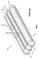
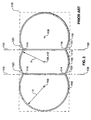
- one conventional pressure vessel 100 includes several lobes 102 secured together. Each lobe 102 is geometrically defined as a portion of a "tube-and-dome" shape. Geometrically, a tube-and-dome includes a straight tube 104 which is circular with radius R in transverse cross-section (see Figure 2). Two lobes 102 are combined by slicing each lobe 102 along a plane 106 that is parallel to the longitudinal axis 108 of the tube 104.
- Each of one or more center lobes 110 is thus sliced along two planes 106 parallel to the longitudinal axis 112 of the center lobe's tube.
- the lobes 102 are not tangent to one another at junctions 114 where they meet.
- Each tube 104 is capped at each end by a portion of a hemispherical dome 116 having the same radius R as the tube 104.
- Such tube-and-dome containers have several drawbacks when employed in applications requiring substantially rectangular pressure vessels.
- Such applications include, but are not limited to, storage of CNG for use in fueling a vehicle.
- the vehicle may be a vehicle retrofitted with CNG tanks after previously being fueled by gasoline, or it may be a vehicle designed from the start to run on CNG.
- Arranging truncated portions of several tube-and-dome lobes 102 together to form the pressure vessel 100 improves the approximation, but large wedge-shaped unused volumes 120 nonetheless remain which are not used for CNG storage.
- the unused volumes 120 which are defined by the circular walls of adjacent tube-and-dome lobes 102, may occupy a significant percentage of the internal volume of the rectangular shell 118. Eliminating the unused volumes 120 entirely would require a CNG container which is substantially a rectangular shell in shape. But building a rectangular shell-shaped CNG vessel sufficiently strong to resist typical CNG storage pressures would require excessively thick walls, because the rectangular shell is so far removed in shape from a sphere.
- the vessel 100 has the disadvantage that the lobes 102 tend to peel apart at the junctions 114 because of stresses that occur at the junctions 114. Thickening the walls of the lobes 102 to overcome the peeling tendency reduces the storage capacity of the container 100 or increases its size, and also increases the container's weight.
- DE-C-3151425 discloses a pressure vessel in which tanks 1, 2 and 3 function as monolayer users with a band 6 providing an outer wall or casing.
- Such a pressure vessel is disclosed and claimed herein.
- the present invention provides a pressure vessel having a novel geometry.
- the pressure vessel is configured to resist pressure from compressed natural gas ("CNG") stored within the vessel and the vessel approximates the rectangular shape of a conventional gasoline tank.
- CNG compressed natural gas
- the pressure vessel resists a normal operating pressure of up to about 24.8 Mpa (3,600 p.s.i.) and has sufficient burst strength to resist about three times the normal operating pressure, namely, a burst strength of about 75.8MPa (11,000 p.s.i.).
- novel geometry of the present pressure vessel is described herein through reference to geometric operations such as slicing a shape with a plane. These geometric operations do not necessarily correspond to manufacturing methods, but are rather illustrations of the geometry of the pressure vessel to be manufactured.
- One embodiment of the present vessel includes two end cells.
- Each end cell includes a semi-cylindrical outer wall.
- the outer wall geometry is defined by slicing a first cylindrical container with a plane through its longitudinal axis to create a half-cylinder.
- Each end cell also includes a quarter-cylindrical upper wall and a quarter-cylindrical lower wall.
- the upper wall and lower wall are unitary with the outer wall.
- the upper wall geometry is defined by slicing a second cylindrical container which has the same length as the first cylindrical container but which also has a smaller radius.
- the second cylindrical container is sliced with two perpendicular planes through its longitudinal axis.
- the lower wall is similarly defined by slicing a third cylindrical container with two perpendicular planes.
- a rectangular section connects the lower end of the upper wall with the upper end of the lower wall.
- the end of each cell thus defines a curve which is herein denoted a "polyradial" curve, in reference to the differing radii of the outer and upper-or-lower walls.
- Each end of the joined half- and quarter-cylindrical walls is capped by a cap.
- Each cap corresponds in shape (not necessarily in materials actually employed) to an elastic sheet secured to a closed polyradial curve as a boundary condition and then subjected to a uniform deformation pressure.
- the novel geometry of the present invention is further illustrated by a cross-section taken transverse to the longitudinal axis of one of the end cells.
- the cross-section defines a polyradial curve which includes an arcuate outer wall, an arcuate upper wall, and an arcuate lower wall.
- the outer wall corresponds to the semi-cylinder with the larger radius, which is therefore termed the outer wall radius.
- the upper wall which has one end unitary with the outer wall at an upper-outer junction, corresponds to the upper quarter-cylinder, and thus has an upper wall radius that is less than the outer wall radius.
- the lower wall which has one end unitary with the outer wall at a lower-outer junction, corresponds to the lower quarter-cylinder.
- the lower wall radius is equal to the upper wall radius, but these radii may differ in other embodiments.
- a polyradial cross-section may include circular arcs having either two or three different radii.
- each interior cell has a semi-cylindrical upper portion secured to a semi-cylindrical lower portion by two straight inner walls.
- the interior cells are secured tangent to and adjacent to one another, with the end cells secured tangent to and adjacent to the outermost interior cells.
- the radii of the semi-cylindrical interior wall upper and lower portions are the same as the radii of the quarter-cylindrical upper wall and lower wall, respectively, of the end cells.
- the end cells and interior cells of the present pressure vessel are generally tangent to one another where they meet, unlike the lobes of previously known pressure vessels. This aspect of the novel geometry of the present pressure vessel reduces the tendency of adjacent cells to peel apart.
- a web is secured about the end cells and about any interior cells that are present.
- the web includes a substantially planar upper sheet which is generally tangent to the upper-outer junction of each of the end cells and to the semi-cylindrical upper portion of each interior cell.
- the web also includes a substantially planar lower sheet which is generally tangent to the lower-outer junction of each of the end cells and to the semi-cylindrical lower portion of each interior cell. The web strengthens the pressure vessel by assisting in holding the cells tangent to one another and by reinforcing the cell walls.
- the pressure vessel of the present invention defines wedge-shaped unused volumes between the web and the cells that are not used for pressurized fluid storage.
- the pressure vessel is strengthened by substantially filling the unused volumes with wedges of foam or rubber disposed between the web sheets and the cells.
- the pressure vessel of the present invention includes a valve capable of selectively providing fluid communication between an interior chamber of the pressure vessel and an exterior pressurized fluid line such as a CNG line connected to the valve.
- the interiors of the several cells that form the present pressure vessel are configured to be in fluid communication with one another, so that only one valve is needed to control fluid flow in and out of the pressure vessel.
- the valve includes a pressure relief mechanism to bleed off pressurized fluid if the internal pressure of the pressure vessel exceeds a predetermined value.
- the valve also includes a fusible plug to provide emergency venting in the presence of high temperatures.
- the pressure vessel of the present invention facilitates retrofitting gasoline-fueled vehicles because the filled weight of the pressure vessel does not exceed the filled weight of a conventional gasoline tank occupying substantially the same volume envelope.
- the pressure vessel may be configured with fixtures defining exterior recesses capable of engaging conventional gasoline tank straps.
- the same tank straps previously used to secure the gasoline tank to the vehicle can be used, without substantial alteration or further testing, to secure the pressure vessel to the vehicle.
- the pressure vessel of the present invention is not limited to use in retrofitting vehicles.
- the present invention also has applications in the design of new vehicles, as well as in other applications which benefit from the use of pressure vessels having a substantially rectangular shape.
- Pressure vessels according to the present invention are manufactured with metal or composite parts.
- the cells are formed of a liner such as a metallic foil or a synthetic polymer film to provide gas impermeability.
- the liner is overwrapped by a composite layer using filament winding or another method familiar to those of skill in the art.
- Interior ports may be provided in the cell walls for fluid communication between cells, or an external manifold may be subsequently attached to provide such communication.
- the cells are positioned adjacent one another, and all the cells are then overwrapped by a composite web.
- the composite used in the cells, the web, or both may include carbon, glass, graphite, aramid, or other known fibers bound in a thermoplastic or thermoset resin.
- the cells are formed of metal by stamping, extruding, or another process familiar to those of skill in the art.
- the metal pieces are welded together, and are then overwrapped with a composite web.
- suitable metals are titanium, aluminum, and steel.
- the present invention provides a pressure vessel in which the cells meet tangentially and are overwrapped with a reinforcing web.
- the novel geometry of the pressure vessel provides generally circular cross-sections which resist the tendency to peel apart in response to internal pressure.
- the exterior of the pressure vessel conforms generally to the external shape of a conventional gasoline tank and includes fixtures defining recesses to engage conventional gasoline tank straps.
- the present invention relates to a pressure vessel generally, and more specifically to a tank for holding compressed natural gas ("CNG") for fueling a vehicle (not shown).
- CNG compressed natural gas
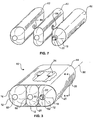
- One embodiment of the present pressure vessel is indicated generally at 10 in Figure 3.
- This embodiment of the pressure vessel 10 includes three cells 12 secured within a web 14.
- the three cells 12 include a left end cell 16, a right end cell 18, and one interior cell 20.
- the cells 12 have a novel geometry and other important characteristics which will be described in detail after the other main components of the pressure vessel 10 are noted.
- the right end cell 18 is preferably configured with a valve 22 to control fluid flow in and out of the pressure vessel 10.
- the valve 22 preferably includes pressure relief means for the controlled release of pressurized fluid from the pressure vessel 10 if the internal pressure of the pressure vessel 10 exceeds a predetermined value.
- the pressurized fluid is CNG and the predetermined value for controlled fluid release is about 24.8MPa (3,600 p.s.i).
- Suitable pressure relief means include a mechanical pressure relief mechanism of the type familiar in the art which is configured to bleed off CNG at a set predetermined pressure.
- Suitable pressure relief means also preferably includes a fusible plug to provide emergency venting in the presence of high temperatures, such as temperatures which could raise the pressure within the pressure vessel 10 above the predetermined value. It is presently preferred that the fusible plug be configured to provide emergency venting when temperatures in the tank rise above about 212 degrees Fahrenheit.
- the pressure vessel 10 could also be usefully configured with the valve 22 at another location or with more than one valve.
- Wedge-shaped supports 24 are positioned to extend lengthwise between the cells 12 and the web 14. For clarity of illustration, portions of these supports 24 have been cut away in Figure 3.
- the supports 24 generally fill the wedge-shaped unused volume between the cells 12 and the web 14 to provide structural support to the web 14. Suitable materials for the supports 24 include rubber, resilient foam, and other rigid or semi-rigid materials familiar to those in the art.
- the exterior of the pressure vessel 10 is configured with fixtures defining recesses 25 for accepting and retaining conventional gasoline tank straps (not shown). It is presently preferred in retrofitting applications that the exterior of the pressure vessel 10 also conform generally in shape to a conventional gasoline tank, both in its generally rectangular shape and in its dimensions.
- the recesses 25 and other conforming features of the pressure vessel 10 facilitate replacement of a conventional gasoline tank with the pressure vessel 10 during conversion of the vehicle from a gasoline-fueled configuration to a CNG-fueled configuration.
- the end cell 18 includes an outer wall 26 disposed about a liner 28.
- the outer wall 26 is preferably made of a composite material, such as carbon, glass, graphite, aramid, or other known fibers bound in a thermoplastic or thermoset resin such as epoxy.
- the liner 28 may be made of a gas impermeable material, such as a metallic foil or a synthetic polymer film.
- the outer wall 26 is generally semi-cylindrical.
- the geometry of the outer wall 26 is defined by slicing a first cylinder with a plane through a longitudinal axis 30.
- the longitudinal axis 30 extends through a point 32 perpendicular to the plane of Figure 4.
- the radius 34 of the outer wall 26 is thus substantially constant through an arc of about 180 degrees.
- a generally quarter-cylindrical upper wall 36 and a generally quarter-cylindrical lower wall 38 are attached to the outer wall 26.
- the upper wall 36 is unitary with the outer wall 26 at an upper-outer junction 40
- the lower wall 38 is unitary with the outer wall 26 at a lower-outer junction 42.
- the quarter-cylindrical geometry of the walls 36 and 38 is defined by slicing a second and third cylinder which each have the same length as the outer wall 26 cylinder but which also have smaller tube radii 44 and 46, respectively.
- Each of the second and third cylinders is sliced with two perpendicular planes through its longitudinal axis to define the quarter-cylinder.
- the upper half of the outer wall 26 and the upper wall 36 thus define a polyradial curve.
- the lower half of the outer wall 26 and the lower wall 38 define a second polyradial curve.
- the radius 44 of the upper wall 36 equals the radius 46 of the lower wall 38, but in alternative embodiments these radii differ.
- the radius 34 of the outer wall 26 is always larger than either of the radii 44 and 46.
- a substantially straight inner wall 48 connects the upper wall 36 and the lower wall 38.
- the inner wall 48 is unitary with the upper wall 36 and the lower wall 38 at an upper-inner junction 50 and a lower-inner junction 52, respectively.
- the inner wall 48 is generally tangent to the upper wall 36 at the upper-inner junction 50 and is generally tangent to the lower wall 38 at the lower-inner junction 52.
- the web 14 ( Figure 3) includes an upper sheet 54 which is generally tangent to the upper wall 36 at the upper-outer junction 40.
- the web 14 also includes a lower sheet 56 which is generally tangent to the lower wall 38 at the lower-outer junction 42.
- the upper sheet 54 and the upper wall 36 substantially define an unused volume 58 which is not used for storing pressurized fluid.
- the lower sheet 56 and the lower wall 38 substantially define a similar unused volume 60.
- the unused volumes 58, 60 are preferably substantially filled by the wedge-shaped supports 24 ( Figure 3).
- each end of each cell 12 with a cap 62.
- the caps 62 on the end cells 16, 18 have a geometry which interpolates smoothly between a portion of a sphere having a radius equal to the outer wall radius 34, on the one hand, and portions of spheres having the upper wall radius 44 and the lower wall radius 46, on the other hand.
- the geometry of the caps 62 on the interior cell 20 interpolates smoothly between a portion of a sphere having a radius equal to the outer wall radius 34, on the one hand, and portions of spheres having the upper wall radius 44 and the lower wall radius 46, on the other hand.
- the caps 62 have different geometries which smoothly blend spheres having the three radii 34, 44, and 46.
- each cap 62 corresponds in shape to a hypothetical elastic sheet which is secured to the closed polyradial curve defined by the end of the cell 12 and then subjected to a uniform deformation pressure.
- the end of the cell 12 defines a boundary condition and the shape of the cap 62 is determined by manipulating differential equations corresponding to deformation of the uniform sheet by spatially uniform forces such as gas pressure.
- Figures 5 and 6 illustrate two alternative embodiments of the pressure vessel of the present invention. Each embodiment is shown sectioned along a line corresponding generally in position to the line 4-4 in Figure 3. Although the embodiment shown in Figure 5 includes a left end cell 16 and a right end cell 18, it includes no interior cell 20. By contrast, the embodiment shown in Figure 6 includes a left end cell 16, a right end cell 18, and two interior cells 20. More generally, embodiments of the pressure vessel of the present invention may include zero or more interior cells.
- each interior cell 20 has a substantially semi-circular upper cross-section 21 which is generally tangent to either the upper wall 36 of an end cell 16, 18 or to the semi-circular upper cross-section 21 of another interior cell 20.
- Each interior cell 20 also has a substantially semi-circular lower cross-section 23 which is generally tangent to either the lower wall 38 of an end cell 16, 18 or to the semi-circular lower cross-section 23 of another interior cell 20.
- the radius of each semi-circular upper cross-section 21 substantially equals the upper wall radius of the upper walls 36.
- the interior chambers of the cells 12 of the pressure vessels may be placed in fluid communication with one another by one or more ports 64.
- the pressure within the interiors of the cells 12 is equalized, and only one valve 22 is needed to control the flow of pressurized fluid in and out of the pressure vessel.
- An alternative embodiment, illustrated in Figure 8, provides fluid communication between the cells 12 through an external manifold 66.
- the manifold is constructed of metal or other familiar materials.
- the pressure relief valve 22 and fusible plug are integrated into the manifold 66.
- pressure vessels illustrated in Figures 3 through 6 are generally in the form of one row of cylinders
- alternative embodiments employ the novel geometry of the present invention in pressure vessels having other general forms.
- some embodiments include generally toroidal cells which have in cross-section the novel geometry of the present invention.
- a cross-section of each of the four end cells includes at least one polyradial curve, and may include two polyradial curves in the form of a quarter-circular outer wall that is unitary with two smaller quarter-circular walls.
- the web is generally tangent to the end cell at the junctions between the outer wall and the unitary smaller walls, and the various cells are generally tangent where they meet one another.
- the present pressure vessel is manufactured by methods familiar to those of skill in the art.
- One approach forms the cells 12 by placing the liner 28 ( Figure 4) around a mandrel (not shown) which has the desired geometry and dimensions.
- the desired mandrel geometry which provides for tangential meetings between the cells 12 (see Figures 5 and 6) and the other novel geometric features of the present invention, is readily determined by those of skill in the art according to the teachings herein.
- the desired mandrel dimensions are readily determined by those of skill in the art from information which includes the strength of the materials used to form the cells 12, the pressures the cells 12 must resist, and the dimensions of the space into which the finished pressure vessel must fit.
- the materials used to form the cells 12 include preimpregnated graphite tow which is wound with a combination of hoop and helical windings to provide sufficient strength to resist a standard operating pressure within the pressure vessel of about 24.8MPa (3,600 p.s.i.) and a burst strength of about two to three times that pressure.
- the overall dimensions of this embodiment of the pressure vessel are generally those of the conventional gasoline tank (not shown) which the pressure vessel replaces.
- the present pressure vessel may also be utilized in applications other than retrofitting gasoline-fueled vehicles for CNG usage, in which case criteria other than the size of a conventional gasoline tank will define the desired dimensions of the pressure vessel.
- the liner 28 is overwrapped by composite material using filament winding, tube rolling, tape wrapping, automated fiber placement, or another method familiar to those of skill in the art.
- Aligned ports 64 may be configured in the walls of the cells 12 either by machining after the composite of the cell wall has cured or by placing the composite fibers around a suitable fixture.
- the valve 22 is secured to one of the end cells 18 by a metal polar boss.
- the cells 12 are then positioned adjacent one another as shown in Figure 3.
- the rubber or foam supports 24 are placed or glued against the cells 12.
- the cells 12 are overwrapped by the composite web 14.
- the web 14 includes known composite materials and is applied by filament winding or another application technique familiar to those of skill in the art.
- the full assembly is then placed in a clamshell mold (not shown).
- the mold is generally box-shaped with silicone rubber inserts that match the inside of the box on one side and the desired exterior pressure vessel shape on the other.
- a combination of silicone insert expansion and pressurization of the cell liners 28 is then employed to compact the composite material to the desired shape.
- the cells 12 are formed of metal by stamping, extruding, or another process familiar to those of skill in the art.
- the metal pieces are welded together and are then overwrapped with the composite web 14.
- Suitable metals include titanium, aluminum, and steel.
- the present invention provides a pressure vessel which approximates the internal volume of a conventional gasoline tank.
- the geometry of the cells utilizes upper walls and lower walls whose radii are smaller than the radius of the outer wall. Because the cells meet tangentially, and because the web is tangential to the cells and supports the cells, the pressure vessel of the present invention has generally circular cross-sections that resist the tendency to peel apart.
- the present pressure vessel conforms to the external shape of a conventional gasoline tank.
- the exterior of the present pressure vessel is generally rectangular and is provided with fixtures defining recesses to engage the straps that previously held the gasoline tank to the vehicle.
Landscapes
- Engineering & Computer Science (AREA)
- Mechanical Engineering (AREA)
- General Engineering & Computer Science (AREA)
- Chemical & Material Sciences (AREA)
- Sustainable Development (AREA)
- Sustainable Energy (AREA)
- Life Sciences & Earth Sciences (AREA)
- Combustion & Propulsion (AREA)
- Transportation (AREA)
- Filling Or Discharging Of Gas Storage Vessels (AREA)
- Glass Compositions (AREA)
- Supply Devices, Intensifiers, Converters, And Telemotors (AREA)
- Stackable Containers (AREA)
- Medicines Containing Material From Animals Or Micro-Organisms (AREA)
- Measuring Fluid Pressure (AREA)
Claims (29)
- Druckbehälter (10), umfassend:wenigstens zwei Endzellen (16, 18), wobei jede der Endzellen (16, 18) einen Querschnitt hat, umfassend:eine bogenförmige äußere Wand (26), die einen im Wesentlichen konstanten äußeren Wandradius (34) definiert;eine bogenförmige obere Wand (36), die ein Ende hat, das einheitlich bzw. unitär bzw. einstofflich bzw. einkomponentig bzw. mit der äußeren Wand (26) an einer oberen-äußeren Verbindung (40) ist, wobei die obere Wand (36) einen im Wesentlichen konstanten oberen Wandradius (44) definiert, welcher geringer als der äußere Wandradius (34) ist;eine bogenförmige untere Wand (38), die ein Ende hat, das einheitlich bzw. unitär bzw. einstofflich bzw. einkomponentig mit der äußeren Wand (26) an einer unteren-äußeren Verbindung (42) ist, wobei die untere Wand (38) einen im Wesentlichen konstanten unteren Wandradius (46) definiert, welcher geringer als der äußere Wandradius (34) ist; undeine innere Wand (48), die ein oberes Ende hat, das einheitlich bzw. unitär bzw. einstofflich bzw. einkomponentig mit der oberen Wand (36) an einer oberen-inneren Verbindung (50) ist und ein unteres Ende hat, das einheitlich bzw. unitär bzw. einstofflich bzw. einkomponentig mit der unteren Wand (38) an einer unteren-inneren Verbindung (52) ist; undeinen Steg bzw. eine Bahn (14), der bzw. die um die Endzellen befestigt ist, wobei der Steg bzw. die Bahn (14) eine im Wesentlichen planare obere Platte bzw. Dünnplatte bzw. Folie bzw. einen im Wesentlichen planaren oberen Streifen (54) umfasst, welche bzw. welcher generell tangential zu der oberen-äußeren Verbindung (40) von jeder der Endzellen (16, 18) ist, und eine im Wesentlichen planare untere Platte bzw. Dünnplatte bzw. Folie bzw. einen im Wesentlichen planaren unteren Streifen (56), welche bzw. welcher generell tangential zu der unteren-äußeren Verbindung (42) von jeder der Endzellen (16, 18) ist, dadurch gekennzeichnet, dass der Querschnitt von jeder der Endzellen (16, 18) weiter eine Einlage (28) umfasst, die von einer Verbundzellenwand bzw. zusammengesetzten Zellenwand umgeben ist, wobei die Verbundzellenwand bzw. zusammengesetzte Zellenwand die äußere Wand (26), die obere Wand (36), die untere Wand (38) und die innere Wand (48) umfasst.
- Druckbehälter nach Anspruch 1, worin der Steg bzw. die Bahn (14) ein Verbundmaterial bzw. zusammengesetztes Material umfasst.
- Druckbehälter nach Anspruch 1, worin jede der Endzellen (16, 18) einen im Wesentlichen halbzylindrischen Teil umfasst.
- Druckbehälter nach Anspruch 1, worin der äußere Wandradius (34) im Wesentlichen der gleiche für jede der äußeren Wände (26) ist und der obere Wandradius (44) im Wesentlichen der gleiche für jede der oberen Wände (36) ist.
- Druckbehälter nach Anspruch 1, worin der obere Wandradius (44) und der untere Wandradius (46) im Wesentlichen gleich sind.
- Druckbehälter nach Anspruch 1, worin eine innere Zelle (20) benachbart von wenigstens einer der oberen Wände (36) und benachbart von wenigstens einer der unteren Wände (38) befestigt ist und der Steg bzw. die Bahn (14) um die innere Zelle (20) befestigt ist.
- Druckbehälter nach Anspruch 6, worin ein Teil der inneren Zelle (20) benachbart dem Steg bzw. der Bahn (14) einen im Wesentlichen halbkreisförmigen oberen Querschnitt hat.
- Druckbehälter nach Anspruch 7, worin der im Wesentlichen halbkreisförmige obere Querschnitt der inneren Zelle (20) im Großen und Ganzen tangential zu der oberen Wand (36) von wenigstens einer der Endzellen (16, 18) ist.
- Druckbehälter nach Anspruch 7, worin ein Radius des im Wesentlichen halbkreisförmigen oberen Querschnitts der inneren Zelle (20) im Wesentlichen gleich dem oberen Wandradius (44) von wenigstens einer der oberen Wände (36) ist.
- Druckbehälter nach Anspruch 1, worin wenigstens zwei innere Zellen (20) zwischen den Endzellen (16, 18) befestigt sind, wobei jede der oberen Wände (36) der Endzellen (16, 18) benachbart von wenigstens einer der inneren Zellen (20) ist, und worin der Steg bzw. die Bahn (14) um die inneren Zellen (20) befestigt ist.
- Druckbehälter nach Anspruch 1, weiter umfassend ein Ventil (22), das fähig ist, wahlweise eine Fluidverbindung zwischen einer inneren Kammer des Druckbehälters (10) und einer mit dem Ventil (22) verbundenen äußeren Druckfluidleitung vorzusehen.
- Druckbehälter nach Anspruch 1, weiter umfassend einen Keil (24), der zwischen der oberen Platte bzw. Dünnplatte bzw. Folie bzw. dem oberen Streifen (54) des Stegs bzw. der Bahn (14) und wenigstens einer der oberen Wände (36) zum Beschränken von Kräften angeordnet ist, welche die obere Platte bzw. Dünnplatte bzw. Folie bzw. den oberen Streifen (54) nach der oberen Wand (36) zu drängen.
- Druckbehälter nach Anspruch 1, worin jedes Ende von jeder der Endzellen (16, 18) und irgendwelcher inneren Zellen (20) eine jeweilige individuelle Endkappe (62) umfassen.
- Druckbehälter nach Anspruch 1, worin die inneren Wände (48) der Endzellen (16, 18) und irgendwelcher inneren Zellen (20) jede mit wenigstens einem Durchlass (64) zum Vorsehen einer Fluidverbindung zwischen den Inneren der Zellen (12) konfiguriert sind.
- Druckbehälter nach Anspruch 1, worin die Zellen (12) des Druckbehälters (10) mit einem äußeren Verteiler bzw. einer äußeren Sammelleitung (66) konfiguriert sind, der bzw. die eine Fluidverbindung zwischen den Inneren der Zellen (12) vorsieht.
- Druckbehälter nach Anspruch 1, worin die Verbundzellenwand bzw. die zusammengesetzte Zellenwand aus vorimprägniertem Seil bzw. Kabel bzw. Werg ausgebildet ist, das um die Einlage (28) mit einer Kombination von Ringwicklungen und spiralförmigen Wicklungen gewickelt ist.
- Druckbehälter nach Anspruch 1, worin:die äußere Wand (26) im Wesentlichen halbkreisförmig ist;die obere Wand (36) im Wesentlichen viertelkreisförmig ist;die untere Wand (38) im Wesentlichen viertelkreisförmig ist; und der untere Wandradius (46) im Wesentlichen gleich dem oberen Wandradius (44) ist; unddie innere Wand (48) im Wesentlichen gerade ist.
- Druckbehälter nach Anspruch 17, worin der Steg bzw. die Bahn (14) ein Verbundmaterial bzw. zusammengesetztes Material umfasst.
- Druckbehälter nach Anspruch 18, weiter umfassend einen oberen Keil (24), der zwischen der oberen Platte bzw. Dünnplatte bzw. Folie bzw. dem oberen Streifen (54) des Stegs bzw. der Bahn (14) und wenigstens einer der oberen Wände (36) zum Widerstehen von Kräften angeordnet ist, welche die obere Platte bzw. Dünnplatte bzw. Folie bzw. den oberen Streifen (54) nach der oberen Wand (36) zu drängen, und einen unteren Keil (24), der zwischen der unteren Platte bzw. Dünnplatte bzw. Folie bzw. dem unteren Streifen (56) des Stegs bzw. der Bahn (14) und wenigstens einer der unteren Wände (38) zum Widerstehen von Kräften angeordnet ist, welche die untere Platte bzw. Dünnplatte bzw. Folie bzw. den unteren Streifen (56) nach der unteren Wand (38) zu drängen.
- Druckbehälter nach Anspruch 18, worin wenigstens zwei innere Zellen (20) zwischen den Endzellen (16, 18) befestigt sind, wobei jede der oberen Wände (36) der Endzellen (16, 18) benachbart von wenigstens einer der inneren Zellen (20) ist, und wobei der Steg bzw. die Bahn (14) um die inneren Zellen (20) befestigt ist.
- Druckbehälter nach Anspruch 20, worin ein Teil von jeder der inneren Zellen (20) einen im Wesentlichen halbkreisförmigen oberen Querschnitt benachbart der oberen Platte bzw. Dünnplatte bzw. Folie bzw. dem oberen Streifen (54) des Stegs bzw. der Bahn (14) hat, wobei wenigstens einer der im Wesentlichen halbkreisförmigen oberen Querschnitte im Großen und Ganzen tangential zu wenigstens einer der oberen Wände (36) der Endzellen (16, 18) ist, wobei jede der inneren Zellen (20) einen im Wesentlichen halbkreisförmigen unteren Querschnitt benachbart der unteren Platte bzw. Dünnplatte bzw. Folie bzw. dem unteren Streifen (56) des Stegs bzw. der Bahn (14) hat, und wenigstens einer der im Wesentlichen halbkreisförmigen unteren Querschnitt im Großen und Ganzen tangential zu wenigstens einer der unteren Wände (38) der Endzellen (16, 18) ist.
- Druckbehälter nach Anspruch 18, worin der Druckbehälter (10) mit Vorrichtungen (25) konfiguriert ist, welche äußere Vertiefungen begrenzen, die fähig sind, mit Betriebsstoffbzw. Benzintankbändern bzw. -streifen bzw. -verbindungsstücken in Eingriff zu treten, welche fähig sind, den Druckbehälter (10) an einem Fahrzeug zu befestigen.
- Druckbehälter nach Anspruch 18, worin jedes Ende von jeder der Endzellen (16, 18) und irgendwelcher inneren Zellen (20) eine jeweilige individuelle Endkappe (62) umfasst.
- Druckbehälter nach Anspruch 18, worin die inneren Wände (48) der Endzellen (16, 18) und irgendwelcher inneren Zellen (20) jede mit wenigstens einem Durchlass (64) zum Vorsehen einer Fluidverbindung zwischen den Inneren der Zellen (12) konfiguriert sind.
- Druckbehälter nach Anspruch 18, worin die Zellen (12) des Druckbehälters (10) mit einem äußeren Verteiler bzw. einer äußeren Sammelleitung (66) konfiguriert sind, welcher bzw. welche eine Fluidverbindung zwischen den Inneren der Zellen (12) vorsieht.
- Druckbehälter nach Anspruch 18, weiter umfassend ein Ventil (22), das fähig ist, wahlweise eine Fluidverbindung mit einer inneren Kammer des Druckbehälters (10) vorzusehen.
- Druckbehälter nach Anspruch 26, worin das Ventil (22) einen schmelzbaren Stopfen umfasst.
- Druckbehälter nach Anspruch 26, worin das Ventil (22) einen mechanischen Druckentspannungsmechanismus umfasst, der zum Abblasen von Druckfluid bei einem vorbestimmten Druck konfiguriert ist.
- Druckbehälter nach Anspruch 18, worin die Verbundzellenwand bzw. die zusammengesetzte Zellenwand aus vorimprägniertem Seil bzw. Kabel bzw. Werg gebildet ist, das um die Einlage (28) mit einer Kombination von Ringwindungen und spiralförmigen Windungen gewickelt ist.
Applications Claiming Priority (3)
| Application Number | Priority Date | Filing Date | Title |
|---|---|---|---|
| US08/382,502 US5577630A (en) | 1995-02-02 | 1995-02-02 | Composite conformable pressure vessel |
| PCT/US1996/000363 WO1996023721A1 (en) | 1995-02-02 | 1996-01-11 | Composite conformable pressure vessel |
| US382502 | 1999-08-25 |
Publications (3)
| Publication Number | Publication Date |
|---|---|
| EP0812293A1 EP0812293A1 (de) | 1997-12-17 |
| EP0812293A4 EP0812293A4 (de) | 1998-11-04 |
| EP0812293B1 true EP0812293B1 (de) | 2002-06-26 |
Family
ID=23509238
Family Applications (1)
| Application Number | Title | Priority Date | Filing Date |
|---|---|---|---|
| EP96904447A Expired - Lifetime EP0812293B1 (de) | 1995-02-02 | 1996-01-11 | Ein zusammengesetzter und anpassungsfähiger druckbehälter |
Country Status (12)
| Country | Link |
|---|---|
| US (3) | US5577630A (de) |
| EP (1) | EP0812293B1 (de) |
| JP (1) | JP3911015B2 (de) |
| KR (1) | KR100499230B1 (de) |
| AT (1) | ATE219753T1 (de) |
| AU (1) | AU690824C (de) |
| CA (1) | CA2212016C (de) |
| DE (1) | DE69622022T2 (de) |
| FI (1) | FI973203A7 (de) |
| NO (2) | NO310791B1 (de) |
| NZ (1) | NZ302486A (de) |
| WO (1) | WO1996023721A1 (de) |
Cited By (2)
| Publication number | Priority date | Publication date | Assignee | Title |
|---|---|---|---|---|
| EP4115115A4 (de) * | 2020-03-04 | 2023-11-29 | Quantum Fuel Systems LLC | Raumanpassbares druckgasspeichersystem |
| WO2025114533A1 (fr) * | 2023-11-30 | 2025-06-05 | Faurecia Hydrogen Solutions France | Réservoir pour gaz sous pression |
Families Citing this family (136)
| Publication number | Priority date | Publication date | Assignee | Title |
|---|---|---|---|---|
| US5577630A (en) | 1995-02-02 | 1996-11-26 | Thiokol Corporation | Composite conformable pressure vessel |
| DE19725369A1 (de) * | 1997-06-16 | 1998-02-05 | Mathias Braune | Nichtzylindrischer Verbundstoffdruckbehälter |
| DE19749950C2 (de) * | 1997-11-03 | 1999-11-25 | Mannesmann Ag | Behälter zum Speichern von Druckgas |
| DE19812904C2 (de) * | 1998-03-18 | 2000-02-03 | Mannesmann Ag | Vorrichtung zum Speichern von Druckgas |
| FR2781555B1 (fr) * | 1998-07-22 | 2000-10-13 | Guy Negre | Concept et procede de fabrication de reservoir de fluide, d'air comprime ou autre gaz a haute pression |
| MY125147A (en) * | 1998-10-27 | 2006-07-31 | Univ Johns Hopkins | Compressed gas manifold |
| NZ513489A (en) | 1999-02-16 | 2002-12-20 | Alliant Techsystems Inc | Closure assembly for lined tanks, and vehicles equipped with the same |
| US6460721B2 (en) | 1999-03-23 | 2002-10-08 | Exxonmobil Upstream Research Company | Systems and methods for producing and storing pressurized liquefied natural gas |
| BR0010305B1 (pt) | 1999-05-03 | 2010-02-09 | grupo de màdulos de fechamento e vaso de pressço de multi-cÉlula. | |
| KR100325737B1 (ko) * | 1999-06-17 | 2002-03-06 | 류정열 | 엘피지용 차량의 다열 일체형 연료탱크연결구조 |
| DE10008985A1 (de) * | 2000-02-25 | 2001-08-30 | Linde Ag | Speicherbehälter |
| US6499646B1 (en) * | 2000-04-05 | 2002-12-31 | Indian Sugar And General Engineering Corp. | Fusion welded liquefiable gas cylinder with overpressure protection heads and method for making the same |
| US6276561B1 (en) * | 2000-08-07 | 2001-08-21 | Alejandro Godoy | Scuba cylinder |
| FR2813378B1 (fr) * | 2000-08-28 | 2002-10-31 | Renault | Dispositif de stockage de fluide sous pression et/ou de reacteurs generant des fluides sous pression, en particulier pour vehicules automobiles |
| EP1286103B1 (de) * | 2001-08-08 | 2009-08-26 | GM Global Technology Operations, Inc. | Behälter zum Speichern von Gas unter hohem Druck |
| ITMC20010086A1 (it) * | 2001-08-20 | 2003-02-20 | Sida Engineering Srl | Serbatoio multicelle per gas in pressione |
| GB0123851D0 (en) * | 2001-10-04 | 2001-11-28 | Pankhurst Design & Development | Dispersing fragrances |
| US6974156B2 (en) * | 2002-03-19 | 2005-12-13 | Honda Giken Kogyo Kabushiki Kaisha | Fuel tank structure |
| JP2003276456A (ja) * | 2002-03-22 | 2003-09-30 | Honda Motor Co Ltd | 燃料タンク構造 |
| US7147124B2 (en) * | 2002-03-27 | 2006-12-12 | Exxon Mobil Upstream Research Company | Containers and methods for containing pressurized fluids using reinforced fibers and methods for making such containers |
| DE10217247A1 (de) | 2002-04-15 | 2003-11-06 | Deutsch Zentr Luft & Raumfahrt | Drucktank |
| DE10217246A1 (de) | 2002-04-15 | 2003-11-06 | Deutsch Zentr Luft & Raumfahrt | Drucktank |
| DE10217245A1 (de) | 2002-04-15 | 2003-11-06 | Deutsch Zentr Luft & Raumfahrt | Drucktank |
| DE10229803B4 (de) * | 2002-07-03 | 2006-07-27 | Eurocopter Deutschland Gmbh | Verbindungsanordnung zur lösbaren Verbindung eines ersten flexiblen Tanks mit einem zweiten flexiblen Tank eines Luftfahrzeugs |
| US6787007B2 (en) | 2002-09-23 | 2004-09-07 | Bechtel Bwxt Idaho, Llc | Polymeric hydrogen diffusion barrier, high-pressure storage tank so equipped, method of fabricating a storage tank and method of preventing hydrogen diffusion |
| FR2847965A1 (fr) * | 2002-12-03 | 2004-06-04 | Renault Sa | Reservoir pour fluides sous pression et procede de fabrication. |
| EP1431096A3 (de) * | 2002-12-18 | 2006-04-26 | Conception et Développement Michelin S.A. | Hochdruckspeicherbehälter zur Lagerung von Kraftstoff auf einem Kraftfahrzeug |
| US7090736B2 (en) * | 2003-02-20 | 2006-08-15 | Essef Corporation | Pressure vessel prestressing technique |
| WO2004110919A2 (en) * | 2003-05-29 | 2004-12-23 | Chapin Manufacturing, Inc. | Stackable pressure vessel |
| NZ527968A (en) | 2003-09-01 | 2006-07-28 | H2Safe Llc | Storage vessel |
| JP4436148B2 (ja) * | 2004-02-09 | 2010-03-24 | 本田技研工業株式会社 | 圧力容器用ライナおよびその製造方法 |
| FR2871091B1 (fr) * | 2004-06-03 | 2008-01-18 | Commissariat Energie Atomique | Procede de fabrication d'une vitesse d'etancheite d'un reservoir de type iv et reservoir de type iv |
| JP4423129B2 (ja) * | 2004-07-29 | 2010-03-03 | 本田技研工業株式会社 | 圧力容器 |
| US7971740B2 (en) * | 2004-07-06 | 2011-07-05 | Honda Motor Co., Ltd. | Pressure vessel |
| JP4332475B2 (ja) * | 2004-07-29 | 2009-09-16 | 本田技研工業株式会社 | 圧力容器 |
| US20060021987A1 (en) * | 2004-07-29 | 2006-02-02 | Smolik John V | Pressurized flat conformal tank |
| AT8860U1 (de) * | 2005-04-13 | 2007-01-15 | Magna Steyr Fahrzeugtechnik Ag | Modularer behälter für kryogene flüssigkeiten |
| DE102005042939A1 (de) * | 2005-09-09 | 2007-03-22 | Still Gmbh | Mobile Arbeitsmaschine mit einem druckbeaufschlagten Tank |
| CN101287946B (zh) * | 2005-09-15 | 2010-04-21 | 曼巴斯阿尔法股份公司 | 分布式气体存贮 |
| EP1938095B1 (de) | 2005-09-29 | 2016-04-13 | Alltech Associates Inc. | Chromatographieverbundsäule |
| FR2893622B1 (fr) | 2005-11-24 | 2007-12-21 | Commissariat Energie Atomique | Composition a base de caprolactame,procede de fabrication d'un element d'etancheite,et reservoir |
| AT9456U1 (de) * | 2006-04-14 | 2007-10-15 | Magna Steyr Fahrzeugtechnik Ag | Behälter für kryogene flüssigkeiten |
| ITMC20060074A1 (it) * | 2006-06-13 | 2007-12-14 | Sida Engineering Srl | Serbatoio multi-celle, perfezionato, per gas in pressione. |
| FR2902364B1 (fr) * | 2006-06-16 | 2012-04-27 | Commissariat Energie Atomique | Procede de fabrication d'une vessie d'etancheite en polymere thermodurcissable pour un reservoir contenant un fluide sous pression, tel qu'un reservoir composite, et reservoir |
| US7744127B2 (en) * | 2006-09-29 | 2010-06-29 | Gm Global Technology Operations, Inc. | Fuel tank mount |
| US9708120B2 (en) | 2006-10-26 | 2017-07-18 | Altair Engineering, Inc. | Storage tank containment system |
| US10352500B2 (en) | 2006-10-26 | 2019-07-16 | Altair Engineering, Inc. | Storage tank containment system |
| US11098850B2 (en) | 2006-10-26 | 2021-08-24 | Altair Engineering, Inc. | Storage tank containment system |
| US8322551B2 (en) | 2006-10-26 | 2012-12-04 | Altair Engineering, Inc. | Storage tank containment system |
| US7708161B2 (en) * | 2006-12-05 | 2010-05-04 | Florida State University Research Foundation | Light-weight vacuum chamber and applications thereof |
| GB0701883D0 (en) * | 2007-02-01 | 2007-03-14 | Polytank Ltd | Storage tanks |
| JP5357060B2 (ja) * | 2007-03-02 | 2013-12-04 | エナシー トランスポート エルエルシー | 圧縮流体の格納容器への流し込み及び流し出しのための装置及び方法 |
| TW200902401A (en) * | 2007-03-13 | 2009-01-16 | Bluescope Bartlett Liners Pty Ltd | Tank liner |
| US20080308081A1 (en) * | 2007-06-18 | 2008-12-18 | Ernest George Geros | Disposable gas system for internal combustion engine |
| US8020722B2 (en) * | 2007-08-20 | 2011-09-20 | Richards Kevin W | Seamless multi-section pressure vessel |
| DE112007003721B4 (de) * | 2007-11-29 | 2013-07-04 | Hui Xiao | Abgedichteter Verbundbehälter zum Aufnehmen und Ausliefern von Pulver-oder Partikelmaterial |
| US8701926B2 (en) * | 2008-06-23 | 2014-04-22 | The Boeing Company | Tank having integral restraining elements and associated fabrication method |
| US8602249B2 (en) * | 2008-07-29 | 2013-12-10 | Ncf Industries, Inc. | Pressure vessel head with inverted neck |
| US8865370B2 (en) * | 2008-08-05 | 2014-10-21 | Societe Bic | Energy storage integrated framework for portable electronic devices |
| US20110062163A1 (en) * | 2009-09-16 | 2011-03-17 | Mann+Hummel Gmbh | Multi-layer coolant reservoir |
| JP2011079493A (ja) * | 2009-10-09 | 2011-04-21 | Toyota Motor Corp | 燃料タンク |
| US8302389B2 (en) * | 2009-11-23 | 2012-11-06 | International Engine Intellectual Property Company, Llc | Urea SCR diesel aftertreatment system |
| GB0922355D0 (en) * | 2009-12-21 | 2010-02-03 | Linde Ag | Pressure vessel |
| ATE550611T1 (de) * | 2010-01-25 | 2012-04-15 | Soterna S Coop | Speicher für wasser unter druck |
| KR101147051B1 (ko) | 2010-04-19 | 2012-05-17 | 주식회사 대유에스이 | 가스 차량용 듀오 탱크 제조 방법 |
| DE102010018093A1 (de) * | 2010-04-24 | 2011-10-27 | Gm Global Technology Operations Llc (N.D.Ges.D. Staates Delaware) | Tankmodul für ein Kraftfahrzeug |
| CN101941559A (zh) * | 2010-08-23 | 2011-01-12 | 董兰田 | 油品专用集装箱 |
| US9114930B2 (en) * | 2011-03-07 | 2015-08-25 | Casella Waste Systems, Inc. | Compressed natural gas vehicle apparatus and method |
| DE202011102744U1 (de) * | 2011-06-10 | 2012-09-13 | Consolar Solare Energiesysteme Gmbh | Druckbelastbarer Segmentspeicher |
| CA2840062C (en) * | 2011-06-27 | 2016-02-09 | Ihi Corporation | Method for constructing low-temperature tank and low-temperature tank |
| US9376049B2 (en) * | 2011-08-22 | 2016-06-28 | Tranzgaz Inc. | Method of fabricating type 4 cylinders and arranging in transportation housings for transport of gaseous fluids |
| US20130092561A1 (en) * | 2011-10-18 | 2013-04-18 | Jörg Wellnitz | Hydrogen Storage System |
| WO2013078210A1 (en) * | 2011-11-21 | 2013-05-30 | Altair Engineering, Inc. | Storage tank containment system |
| US9243751B2 (en) * | 2012-01-20 | 2016-01-26 | Lightsail Energy, Inc. | Compressed gas storage unit |
| DE102012023172A1 (de) * | 2012-11-28 | 2014-06-12 | Kautex Textron Gmbh & Co. Kg | Instationärer Behälter sowie Verfahren zu dessen Herstellung |
| DE102012223676A1 (de) * | 2012-12-19 | 2014-03-13 | Voith Patent Gmbh | Drucktank |
| US9249933B2 (en) * | 2013-03-28 | 2016-02-02 | GM Global Technology Operations LLC | Fluid storage tank |
| US9249931B2 (en) * | 2013-03-28 | 2016-02-02 | GM Global Technology Operations LLC | Fluid storage tank |
| US9533569B2 (en) | 2013-06-18 | 2017-01-03 | The Heil Co. | Tailgate with structurally integrated CNG system |
| US10295309B2 (en) | 2013-07-08 | 2019-05-21 | Loukus Technologies, Inc. | Core structured components and containers |
| CN104421428B (zh) * | 2013-08-23 | 2017-09-15 | 通用汽车环球科技运作有限责任公司 | 流体存储罐 |
| US9366203B2 (en) * | 2013-09-24 | 2016-06-14 | Fca Us Llc | Conformable high pressure gaseous fuel storage system having a gas storage vessel with fractal geometry |
| DE102013111642B9 (de) | 2013-10-22 | 2017-08-03 | Deutsches Zentrum für Luft- und Raumfahrt e.V. | Drucktankbehälter und Drucktank |
| US10060577B2 (en) * | 2013-10-28 | 2018-08-28 | Alternative Fuel Containers, Llc | Fuel gas storage tank with supporting filter tube(s) |
| US9234626B2 (en) | 2013-10-28 | 2016-01-12 | Battelle Memorial Institute | Conformable pressure vessel for high pressure gas storage |
| WO2015069376A1 (en) * | 2013-11-08 | 2015-05-14 | United Technologies Corporation | High conformal pressure vessel |
| WO2015160403A2 (en) * | 2014-01-20 | 2015-10-22 | United Technologies Corporation | Additive manufactured non-round, septum tied, conformal high pressure tubing |
| BR112017007186B1 (pt) * | 2014-10-07 | 2022-03-03 | United Technologies Corporation | Conjunto de recipiente de pressão, e, método para formação de um conjunto de recipiente de pressão |
| EP3204683B1 (de) * | 2014-10-07 | 2020-09-02 | United Technologies Corporation | Druckbehälterfluidverteilerbaugruppe |
| WO2016057024A1 (en) | 2014-10-07 | 2016-04-14 | United Technologies Research Center | Composite pressure vessel assembly and method of manufacturing |
| CN110497789B (zh) | 2014-10-24 | 2022-08-09 | H2赛弗有限公司 | 用于容纳挥发性流体的防故障封闭装置 |
| US10815051B2 (en) * | 2015-06-05 | 2020-10-27 | Intermodal Sciences, Llc | Container for transport of bulk liquids using dry trailers |
| US10465848B1 (en) | 2015-09-21 | 2019-11-05 | Hexagon Technology As | Conformable composite pressure vessel |
| BR112018008530A2 (pt) * | 2015-11-25 | 2018-10-30 | United Technologies Corp | conjunto de recipiente de pressão |
| BR112018008525A2 (pt) | 2015-11-25 | 2018-10-30 | United Technologies Corp | conjunto de recipiente de pressão compósito, e, método de fabricação de um conjunto de recipiente de pressão compósito |
| WO2017091223A1 (en) * | 2015-11-25 | 2017-06-01 | United Technologies Corporation | Composite pressure vessel assembly with an integrated heating element |
| KR101755927B1 (ko) | 2015-12-10 | 2017-07-07 | 현대자동차주식회사 | 차량의 비실린더형 복합재 압력 용기 |
| WO2017167536A1 (de) * | 2016-03-31 | 2017-10-05 | Siemens Aktiengesellschaft | Treibstofftank für ein schienenfahrzeug und schienenfahrzeug mit solch einem treibstofftank |
| EP3445554B1 (de) * | 2016-04-22 | 2026-04-08 | RTX Corporation | Verfahren zur herstellung einer verbundgefässanordnung |
| EP3446025B8 (de) * | 2016-04-22 | 2024-10-09 | RTX Corporation | Verbunddruckbehälteranordnung mit integrierter düsenbaugruppe |
| CA2967403A1 (en) * | 2016-05-16 | 2017-11-16 | Goodrich Corporation | Conformable pressure vessel |
| MX2018013798A (es) * | 2016-05-20 | 2019-03-28 | John Carpenter Bradely | Estabilizador de carga de fluidos. |
| MX2018014064A (es) | 2016-05-21 | 2019-04-04 | Worthington Ind Inc | Metodos y sistemas para soporte de contenedor de combustible alternativo. |
| USD849662S1 (en) | 2016-05-21 | 2019-05-28 | Worthington Industries, Inc. | Cylinder support system |
| USD816010S1 (en) | 2016-05-21 | 2018-04-24 | Worthington Industries, Inc. | Cylinder support system |
| PT3318791T (pt) | 2016-11-07 | 2021-03-02 | Ac Inox Gmbh | Tanque de carga de múltiplos lóbulos |
| JP6601379B2 (ja) | 2016-12-06 | 2019-11-06 | トヨタ自動車株式会社 | 圧力容器および圧力容器の製造方法 |
| US10914401B2 (en) | 2017-01-10 | 2021-02-09 | The Heil Co. | Fuel monitoring system |
| US11333301B2 (en) | 2017-05-15 | 2022-05-17 | Advanced Lightweight Engineering B.V. | Pressure vessel for the storage of pressurized fluids and vehicle comprising such a pressure vessel |
| DE102017212485A1 (de) * | 2017-07-20 | 2019-01-24 | Robert Bosch Gmbh | Einrichtung zur Speicherung von verdichteten Fluiden |
| JP7069597B2 (ja) * | 2017-08-10 | 2022-05-18 | トヨタ自動車株式会社 | 高圧容器 |
| CN111279115B (zh) | 2017-08-31 | 2022-01-04 | 澳汰尔工程公司 | 储存罐容纳系统 |
| FR3078134B1 (fr) * | 2018-02-19 | 2021-06-11 | Mahytec | Reservoir polymorphe |
| WO2020014595A1 (en) | 2018-07-12 | 2020-01-16 | Magna International Inc. | Non-circular pressure vessel |
| US11207974B2 (en) | 2018-09-21 | 2021-12-28 | The Heil Co. | Multiple gas tank assembly with individual pressure monitoring |
| US12240151B2 (en) * | 2019-01-07 | 2025-03-04 | Goodrich Corporation | Composite structure with blind hole |
| US20200347992A1 (en) * | 2019-05-02 | 2020-11-05 | Agility Fuel Systems Llc | Polymeric liner based gas cylinder with reduced permeability |
| ES1240505Y (es) | 2019-08-06 | 2020-07-29 | Monge Antonio Ojeda | Sistema de almacenamiento de gas a alta presion de morfologia adaptable |
| DE102019126592A1 (de) * | 2019-10-02 | 2021-04-08 | Bayerische Motoren Werke Aktiengesellschaft | Unterbodenbaugruppe für ein Kraftfahrzeug und Kraftfahrzeug |
| JP7273762B2 (ja) * | 2020-05-13 | 2023-05-15 | 八千代工業株式会社 | 高圧容器 |
| EP4237738A4 (de) | 2020-10-29 | 2024-09-11 | Noble Gas Systems, Inc. | Lagersystem für anpassbare tanks |
| NO348049B1 (en) * | 2021-02-22 | 2024-07-08 | Lattice Int As | Cellular pressure vessel, method for fabrication and use thereof |
| US11703185B2 (en) * | 2021-03-22 | 2023-07-18 | Ezng Solutions, Llc | Apparatus, systems, and methods for storing and transporting compressed fluids |
| WO2022235947A1 (en) | 2021-05-07 | 2022-11-10 | Agility Fuel Systems Llc | Composite interwoven gas containment assemblies |
| US12358365B1 (en) | 2021-05-07 | 2025-07-15 | Agility Fuel Systems Llc | Vehicles having composite interwoven gas containment assemblies |
| KR102545599B1 (ko) * | 2021-09-23 | 2023-06-21 | 주식회사 티엠씨 | 압축형 연료탱크 |
| DE102021004937A1 (de) * | 2021-10-01 | 2023-04-06 | Mercedes-Benz Group AG | Batteriemodulgehäuse für ein Batteriemodul, Batteriemodul sowie elektrischer Energiespeicher |
| KR102578458B1 (ko) * | 2021-12-28 | 2023-09-14 | 주식회사 티엠씨 | 극저온 액체 연료 탱크 |
| KR102688443B1 (ko) * | 2021-12-28 | 2024-07-25 | 주식회사 티엠씨 | 극저온 액체 연료 탱크 및 그 제조 방법 |
| DE102022116293A1 (de) | 2022-06-30 | 2024-01-04 | Dr. Ing. H.C. F. Porsche Aktiengesellschaft | Druckspeicher |
| CN115493074B (zh) * | 2022-09-23 | 2024-02-02 | 山东产研先进材料研究院有限公司 | 一种集储氢、承载于一体的压力容器 |
| US11969958B1 (en) | 2022-10-07 | 2024-04-30 | Rohr, Inc. | Manufacturing thermoplastic container with internal baffle(s) |
| GB2623549A (en) * | 2022-10-19 | 2024-04-24 | Univ Strathclyde | Pressure vessel |
| DE102022128822A1 (de) * | 2022-10-31 | 2024-05-02 | Raigi | Behälter, umfassend einen mehrteiligen Liner |
| KR102568305B1 (ko) * | 2023-02-03 | 2023-08-21 | 주식회사 티엠씨 | 극저온 유체 저장 탱크 |
| WO2025073324A1 (de) * | 2023-10-06 | 2025-04-10 | Torsten Franke | Druckbehälter zur speicherung von unter druck stehenden fluiden, verfahren zur herstellung desselben |
Family Cites Families (40)
| Publication number | Priority date | Publication date | Assignee | Title |
|---|---|---|---|---|
| US863447A (en) * | 1907-02-02 | 1907-08-13 | Charles H Rice | Squib-box. |
| US1622787A (en) * | 1925-11-05 | 1927-03-29 | George T Horton | Container |
| US1668179A (en) * | 1926-07-15 | 1928-05-01 | Arthur H T Williams | Container |
| US2171973A (en) * | 1935-09-05 | 1939-09-05 | Dominion Oxygen Company Ltd | Safety device for pressure vessels |
| US2095256A (en) * | 1935-10-05 | 1937-10-12 | George T Horton | Container |
| US2726004A (en) * | 1953-01-29 | 1955-12-06 | Philip H Mcleod | Single and multiple container bodies for foodstuff |
| US3765177A (en) | 1959-12-30 | 1973-10-16 | Thiokol Chemical Corp | Rocket motor with blast tube and case bonded propellant |
| US3057509A (en) * | 1960-02-11 | 1962-10-09 | Brunswick Corp | Pressure vessel bladder |
| FR1290641A (fr) * | 1961-05-26 | 1962-04-13 | Ballonfabrik Augsburg Vorm A R | Conteneurs pliants pour le transport des liquides |
| US3171563A (en) * | 1961-10-02 | 1965-03-02 | Brunswick Corp | Rocket motor case |
| US3467118A (en) * | 1967-01-26 | 1969-09-16 | Pomeroy & Co Inc J H | Submerged oil storage facility and method |
| FR1555607A (de) * | 1967-08-31 | 1969-01-31 | ||
| US4123307A (en) * | 1968-07-11 | 1978-10-31 | Lemelson Jerome H | Method for forming hollow shells by rotational casting and winding thereon |
| US3645415A (en) * | 1970-04-23 | 1972-02-29 | Warren Petroleum Corp | Multicylinder tanks |
| DE2062201A1 (de) * | 1970-12-17 | 1972-06-29 | Kochs Adler Ag, 4800 Bielefeld | Fadenabschneideeinrichtung an Doppelsteppstichnähmaschinen |
| JPS5115221A (ja) | 1974-07-26 | 1976-02-06 | Neriki Shokai Kk | Kayoshikianzensen |
| GB1522609A (en) * | 1974-10-18 | 1978-08-23 | Martacto Naviera Sa | Tanks for the storage and transport of fluid media under pressure |
| US4182254A (en) * | 1975-10-16 | 1980-01-08 | Campbell Secord | Tanks for the storage and transport of fluid media under pressure |
| NO140943C (no) | 1977-05-03 | 1979-12-12 | Kvaerner Brug Kjoleavdelning | Tank. |
| US4196808A (en) * | 1978-03-31 | 1980-04-08 | The Procter & Gamble Company | Closure interlock and packaging apparatus |
| GB2032506A (en) * | 1978-10-20 | 1980-05-08 | Kvaerner Brug Kjoleavdelning | Tank |
| GB2040430B (en) * | 1979-01-11 | 1983-02-02 | Ocean Phoenix Holdings Nv | Tanks for storing liquefied gases |
| US4343409A (en) * | 1979-10-22 | 1982-08-10 | Ford Motor Company | Large high temperature plastic vacuum reservoir |
| GB2111663B (en) | 1981-12-16 | 1986-03-26 | Ocean Phoenix Holdings Nv | Tank for the storage and transport of pressurised fluid |
| DE3151425C1 (de) * | 1981-12-24 | 1983-06-09 | Aeg Isolier- Und Kunststoff Gmbh, 3500 Kassel | Kunststoff-Druckbehälter-Verbund |
| US4452971A (en) | 1982-07-19 | 1984-06-05 | Celanese Corporation | Production of improved high molecular weight polybenzimidazole with tin containing catalyst |
| US4589563A (en) * | 1983-03-07 | 1986-05-20 | Quality Products, Inc. | High-pressure container and method of making the same |
| US4817855A (en) * | 1984-10-11 | 1989-04-04 | Allied-Signal Inc. | Pressure vessel |
| US4819426A (en) * | 1987-05-08 | 1989-04-11 | Morton Thiokol, Inc. | Rocket propelled vehicle forward end control method and apparatus |
| US4961699A (en) * | 1988-05-31 | 1990-10-09 | Thiokol Corporation | Apparatus for foaming bubbles |
| US5070691A (en) * | 1988-08-03 | 1991-12-10 | Thiokol Corporation | Solid propellant canister loaded multiple pulsed or staged rocket |
| US4946056A (en) * | 1989-03-16 | 1990-08-07 | Buttes Gas & Oil Co. Corp. | Fabricated pressure vessel |
| US5060470A (en) * | 1990-05-22 | 1991-10-29 | Thiokol Corporation | Gas generator ventable at a high temperature for hazard reduction |
| US5253778A (en) * | 1992-01-28 | 1993-10-19 | Edo Canada Ltd. | Fluid pressure vessel boss-liner attachment system |
| US5237981A (en) * | 1992-02-21 | 1993-08-24 | Pas, Inc. | Fuel injection apparatus for vehicles |
| US5259901A (en) * | 1992-05-27 | 1993-11-09 | Thiokol Corporation | Method for constructing an inflatable mandrel |
| JPH05346198A (ja) | 1992-06-11 | 1993-12-27 | Kobe Steel Ltd | 繊維強化プラスチック容器 |
| JPH06241397A (ja) | 1993-02-15 | 1994-08-30 | Mitsubishi Kasei Corp | 圧力容器およびその製造方法 |
| EP0687587A1 (de) * | 1994-06-13 | 1995-12-20 | Technical Products Group Incorporated | Sicherheitssystem für Druckgefässe |
| US5577630A (en) * | 1995-02-02 | 1996-11-26 | Thiokol Corporation | Composite conformable pressure vessel |
-
1995
- 1995-02-02 US US08/382,502 patent/US5577630A/en not_active Ceased
-
1996
- 1996-01-11 AT AT96904447T patent/ATE219753T1/de not_active IP Right Cessation
- 1996-01-11 JP JP52354996A patent/JP3911015B2/ja not_active Expired - Fee Related
- 1996-01-11 KR KR1019970705258A patent/KR100499230B1/ko not_active Expired - Fee Related
- 1996-01-11 CA CA002212016A patent/CA2212016C/en not_active Expired - Fee Related
- 1996-01-11 EP EP96904447A patent/EP0812293B1/de not_active Expired - Lifetime
- 1996-01-11 WO PCT/US1996/000363 patent/WO1996023721A1/en not_active Ceased
- 1996-01-11 AU AU48551/96A patent/AU690824C/en not_active Ceased
- 1996-01-11 DE DE69622022T patent/DE69622022T2/de not_active Expired - Fee Related
- 1996-01-11 NZ NZ302486A patent/NZ302486A/en not_active IP Right Cessation
- 1996-09-23 US US08/718,611 patent/US6095367A/en not_active Expired - Lifetime
-
1997
- 1997-08-01 NO NO19973558A patent/NO310791B1/no unknown
- 1997-08-01 FI FI973203A patent/FI973203A7/fi unknown
-
2001
- 2001-07-23 NO NO20013616A patent/NO320744B1/no unknown
-
2002
- 2002-03-29 US US10/113,135 patent/USRE41142E1/en not_active Expired - Lifetime
Cited By (4)
| Publication number | Priority date | Publication date | Assignee | Title |
|---|---|---|---|---|
| EP4115115A4 (de) * | 2020-03-04 | 2023-11-29 | Quantum Fuel Systems LLC | Raumanpassbares druckgasspeichersystem |
| EP4425036A3 (de) * | 2020-03-04 | 2024-11-13 | Quantum Fuel Systems LLC | Raumanpassbares druckgasspeichersystem |
| WO2025114533A1 (fr) * | 2023-11-30 | 2025-06-05 | Faurecia Hydrogen Solutions France | Réservoir pour gaz sous pression |
| FR3156185A1 (fr) * | 2023-11-30 | 2025-06-06 | Faurecia Hydrogen Solutions France | Réservoir pour gaz sous pression |
Also Published As
| Publication number | Publication date |
|---|---|
| NO973558L (no) | 1997-09-23 |
| NO20013616L (no) | 1997-09-23 |
| US5577630A (en) | 1996-11-26 |
| WO1996023721A1 (en) | 1996-08-08 |
| NO320744B1 (no) | 2006-01-23 |
| NO310791B1 (no) | 2001-08-27 |
| NO20013616D0 (no) | 2001-07-23 |
| MX9705899A (es) | 1997-10-31 |
| EP0812293A4 (de) | 1998-11-04 |
| EP0812293A1 (de) | 1997-12-17 |
| ATE219753T1 (de) | 2002-07-15 |
| KR100499230B1 (ko) | 2006-01-27 |
| CA2212016C (en) | 2007-06-12 |
| CA2212016A1 (en) | 1996-08-08 |
| JPH10513420A (ja) | 1998-12-22 |
| NZ302486A (en) | 1998-08-26 |
| AU690824B2 (en) | 1998-04-30 |
| AU4855196A (en) | 1996-08-21 |
| DE69622022D1 (de) | 2002-08-01 |
| JP3911015B2 (ja) | 2007-05-09 |
| FI973203A7 (fi) | 1997-10-01 |
| FI973203A0 (fi) | 1997-08-01 |
| DE69622022T2 (de) | 2003-01-16 |
| AU690824C (en) | 2001-11-15 |
| USRE41142E1 (en) | 2010-02-23 |
| NO973558D0 (no) | 1997-08-01 |
| KR19980701861A (ko) | 1998-06-25 |
| US6095367A (en) | 2000-08-01 |
Similar Documents
| Publication | Publication Date | Title |
|---|---|---|
| EP0812293B1 (de) | Ein zusammengesetzter und anpassungsfähiger druckbehälter | |
| US7971740B2 (en) | Pressure vessel | |
| US5865923A (en) | Method of fabricating a dual chamber composite pressure vessel | |
| EP4050249A1 (de) | Hochdruckgasspeichersystem mit anpassbarer morphologie | |
| EP3382258B1 (de) | Druckbehälter | |
| US7028553B2 (en) | Apparatus for delivering pressurized fluid | |
| CA3149336A1 (en) | Reinforced hybrid pressure vessel having a plastic liner and metallic boss | |
| CN111188995B (zh) | 一种多级高压储氢容器及储氢方法 | |
| EP1526325A2 (de) | Aluminium Behälter mit einer Kunststoffbeschichtung | |
| WO1997009561A1 (en) | Dual chamber fluid storage vessel | |
| US9194401B2 (en) | Ultra lightweight and compact accumulator | |
| MXPA97005899A (en) | Pressure container, adjustable, compue | |
| EP3851270B1 (de) | Verfahren zur herstellung eines hochdrucktanks | |
| GB2623549A (en) | Pressure vessel | |
| HK1075487A (en) | Aluminium cylinder with a plastic coating |
Legal Events
| Date | Code | Title | Description |
|---|---|---|---|
| PUAI | Public reference made under article 153(3) epc to a published international application that has entered the european phase |
Free format text: ORIGINAL CODE: 0009012 |
|
| 17P | Request for examination filed |
Effective date: 19970829 |
|
| AK | Designated contracting states |
Kind code of ref document: A1 Designated state(s): AT CH DE DK ES FR GB GR IE IT LI NL PT SE |
|
| RIN1 | Information on inventor provided before grant (corrected) |
Inventor name: BENNETT, JOHN Inventor name: TURNER, DARREL Inventor name: WOLCOTT, EDWARD Inventor name: DAVIS, KEVIN Inventor name: WARNER, MARK, J. Inventor name: KUNZ, RICHARD Inventor name: BLAIR, MICHAEL, D. |
|
| A4 | Supplementary search report drawn up and despatched |
Effective date: 19980922 |
|
| AK | Designated contracting states |
Kind code of ref document: A4 Designated state(s): AT CH DE DK ES FR GB GR IE IT LI NL PT SE |
|
| RAP1 | Party data changed (applicant data changed or rights of an application transferred) |
Owner name: CORDANT TECHNOLOGIES INC. |
|
| 17Q | First examination report despatched |
Effective date: 20001123 |
|
| GRAG | Despatch of communication of intention to grant |
Free format text: ORIGINAL CODE: EPIDOS AGRA |
|
| GRAG | Despatch of communication of intention to grant |
Free format text: ORIGINAL CODE: EPIDOS AGRA |
|
| GRAH | Despatch of communication of intention to grant a patent |
Free format text: ORIGINAL CODE: EPIDOS IGRA |
|
| GRAH | Despatch of communication of intention to grant a patent |
Free format text: ORIGINAL CODE: EPIDOS IGRA |
|
| GRAA | (expected) grant |
Free format text: ORIGINAL CODE: 0009210 |
|
| RAP1 | Party data changed (applicant data changed or rights of an application transferred) |
Owner name: ALLIANT TECHSYSTEMS INC. |
|
| AK | Designated contracting states |
Kind code of ref document: B1 Designated state(s): AT CH DE DK ES FR GB GR IE IT LI NL PT SE |
|
| PG25 | Lapsed in a contracting state [announced via postgrant information from national office to epo] |
Ref country code: NL Free format text: LAPSE BECAUSE OF FAILURE TO SUBMIT A TRANSLATION OF THE DESCRIPTION OR TO PAY THE FEE WITHIN THE PRESCRIBED TIME-LIMIT Effective date: 20020626 Ref country code: LI Free format text: LAPSE BECAUSE OF FAILURE TO SUBMIT A TRANSLATION OF THE DESCRIPTION OR TO PAY THE FEE WITHIN THE PRESCRIBED TIME-LIMIT Effective date: 20020626 Ref country code: GR Free format text: LAPSE BECAUSE OF FAILURE TO SUBMIT A TRANSLATION OF THE DESCRIPTION OR TO PAY THE FEE WITHIN THE PRESCRIBED TIME-LIMIT Effective date: 20020626 Ref country code: CH Free format text: LAPSE BECAUSE OF FAILURE TO SUBMIT A TRANSLATION OF THE DESCRIPTION OR TO PAY THE FEE WITHIN THE PRESCRIBED TIME-LIMIT Effective date: 20020626 Ref country code: AT Free format text: LAPSE BECAUSE OF FAILURE TO SUBMIT A TRANSLATION OF THE DESCRIPTION OR TO PAY THE FEE WITHIN THE PRESCRIBED TIME-LIMIT Effective date: 20020626 |
|
| REF | Corresponds to: |
Ref document number: 219753 Country of ref document: AT Date of ref document: 20020715 Kind code of ref document: T |
|
| REG | Reference to a national code |
Ref country code: GB Ref legal event code: FG4D |
|
| REG | Reference to a national code |
Ref country code: CH Ref legal event code: EP |
|
| REG | Reference to a national code |
Ref country code: IE Ref legal event code: FG4D |
|
| REF | Corresponds to: |
Ref document number: 69622022 Country of ref document: DE Date of ref document: 20020801 |
|
| PG25 | Lapsed in a contracting state [announced via postgrant information from national office to epo] |
Ref country code: PT Free format text: LAPSE BECAUSE OF FAILURE TO SUBMIT A TRANSLATION OF THE DESCRIPTION OR TO PAY THE FEE WITHIN THE PRESCRIBED TIME-LIMIT Effective date: 20020926 Ref country code: DK Free format text: LAPSE BECAUSE OF FAILURE TO SUBMIT A TRANSLATION OF THE DESCRIPTION OR TO PAY THE FEE WITHIN THE PRESCRIBED TIME-LIMIT Effective date: 20020926 |
|
| NLV1 | Nl: lapsed or annulled due to failure to fulfill the requirements of art. 29p and 29m of the patents act | ||
| ET | Fr: translation filed | ||
| PG25 | Lapsed in a contracting state [announced via postgrant information from national office to epo] |
Ref country code: ES Free format text: LAPSE BECAUSE OF FAILURE TO SUBMIT A TRANSLATION OF THE DESCRIPTION OR TO PAY THE FEE WITHIN THE PRESCRIBED TIME-LIMIT Effective date: 20021220 |
|
| REG | Reference to a national code |
Ref country code: CH Ref legal event code: PL |
|
| PG25 | Lapsed in a contracting state [announced via postgrant information from national office to epo] |
Ref country code: IE Free format text: LAPSE BECAUSE OF NON-PAYMENT OF DUE FEES Effective date: 20030113 |
|
| PLBE | No opposition filed within time limit |
Free format text: ORIGINAL CODE: 0009261 |
|
| STAA | Information on the status of an ep patent application or granted ep patent |
Free format text: STATUS: NO OPPOSITION FILED WITHIN TIME LIMIT |
|
| 26N | No opposition filed |
Effective date: 20030327 |
|
| REG | Reference to a national code |
Ref country code: IE Ref legal event code: MM4A |
|
| PGFP | Annual fee paid to national office [announced via postgrant information from national office to epo] |
Ref country code: SE Payment date: 20070129 Year of fee payment: 12 |
|
| PGFP | Annual fee paid to national office [announced via postgrant information from national office to epo] |
Ref country code: DE Payment date: 20070228 Year of fee payment: 12 |
|
| PGFP | Annual fee paid to national office [announced via postgrant information from national office to epo] |
Ref country code: IT Payment date: 20070521 Year of fee payment: 12 |
|
| PGFP | Annual fee paid to national office [announced via postgrant information from national office to epo] |
Ref country code: FR Payment date: 20070117 Year of fee payment: 12 |
|
| EUG | Se: european patent has lapsed | ||
| PG25 | Lapsed in a contracting state [announced via postgrant information from national office to epo] |
Ref country code: DE Free format text: LAPSE BECAUSE OF NON-PAYMENT OF DUE FEES Effective date: 20080801 |
|
| REG | Reference to a national code |
Ref country code: FR Ref legal event code: ST Effective date: 20081029 |
|
| PG25 | Lapsed in a contracting state [announced via postgrant information from national office to epo] |
Ref country code: SE Free format text: LAPSE BECAUSE OF NON-PAYMENT OF DUE FEES Effective date: 20080112 |
|
| PG25 | Lapsed in a contracting state [announced via postgrant information from national office to epo] |
Ref country code: FR Free format text: LAPSE BECAUSE OF NON-PAYMENT OF DUE FEES Effective date: 20080131 |
|
| PG25 | Lapsed in a contracting state [announced via postgrant information from national office to epo] |
Ref country code: IT Free format text: LAPSE BECAUSE OF NON-PAYMENT OF DUE FEES Effective date: 20080111 |
|
| PGFP | Annual fee paid to national office [announced via postgrant information from national office to epo] |
Ref country code: GB Payment date: 20100125 Year of fee payment: 15 |
|
| GBPC | Gb: european patent ceased through non-payment of renewal fee |
Effective date: 20110111 |
|
| PG25 | Lapsed in a contracting state [announced via postgrant information from national office to epo] |
Ref country code: GB Free format text: LAPSE BECAUSE OF NON-PAYMENT OF DUE FEES Effective date: 20110111 |