EP0810039A2 - Système d'enlevage de poussière - Google Patents
Système d'enlevage de poussière Download PDFInfo
- Publication number
- EP0810039A2 EP0810039A2 EP97108466A EP97108466A EP0810039A2 EP 0810039 A2 EP0810039 A2 EP 0810039A2 EP 97108466 A EP97108466 A EP 97108466A EP 97108466 A EP97108466 A EP 97108466A EP 0810039 A2 EP0810039 A2 EP 0810039A2
- Authority
- EP
- European Patent Office
- Prior art keywords
- work
- air
- air sucking
- dust
- brushroll
- Prior art date
- Legal status (The legal status is an assumption and is not a legal conclusion. Google has not performed a legal analysis and makes no representation as to the accuracy of the status listed.)
- Granted
Links
- 239000000428 dust Substances 0.000 title claims abstract description 115
- 238000007599 discharging Methods 0.000 claims description 10
- 238000011144 upstream manufacturing Methods 0.000 claims description 6
- 230000004323 axial length Effects 0.000 claims description 4
- 239000000853 adhesive Substances 0.000 description 6
- 230000001070 adhesive effect Effects 0.000 description 6
- 238000005192 partition Methods 0.000 description 6
- 239000000463 material Substances 0.000 description 3
- 238000004140 cleaning Methods 0.000 description 2
- 230000003247 decreasing effect Effects 0.000 description 2
- 239000000835 fiber Substances 0.000 description 2
- 239000004925 Acrylic resin Substances 0.000 description 1
- 229920000178 Acrylic resin Polymers 0.000 description 1
- 230000000052 comparative effect Effects 0.000 description 1
- 230000007547 defect Effects 0.000 description 1
- 230000001419 dependent effect Effects 0.000 description 1
- 230000000694 effects Effects 0.000 description 1
- 230000007774 longterm Effects 0.000 description 1
- 238000012423 maintenance Methods 0.000 description 1
- 239000002184 metal Substances 0.000 description 1
- 229920006122 polyamide resin Polymers 0.000 description 1
- 239000000843 powder Substances 0.000 description 1
- 238000006748 scratching Methods 0.000 description 1
- 230000002393 scratching effect Effects 0.000 description 1
Images


Classifications
-
- B—PERFORMING OPERATIONS; TRANSPORTING
- B07—SEPARATING SOLIDS FROM SOLIDS; SORTING
- B07B—SEPARATING SOLIDS FROM SOLIDS BY SIEVING, SCREENING, SIFTING OR BY USING GAS CURRENTS; SEPARATING BY OTHER DRY METHODS APPLICABLE TO BULK MATERIAL, e.g. LOOSE ARTICLES FIT TO BE HANDLED LIKE BULK MATERIAL
- B07B4/00—Separating solids from solids by subjecting their mixture to gas currents
-
- B—PERFORMING OPERATIONS; TRANSPORTING
- B08—CLEANING
- B08B—CLEANING IN GENERAL; PREVENTION OF FOULING IN GENERAL
- B08B15/00—Preventing escape of dirt or fumes from the area where they are produced; Collecting or removing dirt or fumes from that area
- B08B15/04—Preventing escape of dirt or fumes from the area where they are produced; Collecting or removing dirt or fumes from that area from a small area, e.g. a tool
-
- B—PERFORMING OPERATIONS; TRANSPORTING
- B08—CLEANING
- B08B—CLEANING IN GENERAL; PREVENTION OF FOULING IN GENERAL
- B08B1/00—Cleaning by methods involving the use of tools
- B08B1/30—Cleaning by methods involving the use of tools by movement of cleaning members over a surface
- B08B1/32—Cleaning by methods involving the use of tools by movement of cleaning members over a surface using rotary cleaning members
- B08B1/34—Cleaning by methods involving the use of tools by movement of cleaning members over a surface using rotary cleaning members rotating about an axis parallel to the surface
-
- B—PERFORMING OPERATIONS; TRANSPORTING
- B08—CLEANING
- B08B—CLEANING IN GENERAL; PREVENTION OF FOULING IN GENERAL
- B08B1/00—Cleaning by methods involving the use of tools
- B08B1/50—Cleaning by methods involving the use of tools involving cleaning of the cleaning members
- B08B1/52—Cleaning by methods involving the use of tools involving cleaning of the cleaning members using fluids
-
- B—PERFORMING OPERATIONS; TRANSPORTING
- B08—CLEANING
- B08B—CLEANING IN GENERAL; PREVENTION OF FOULING IN GENERAL
- B08B1/00—Cleaning by methods involving the use of tools
- B08B1/50—Cleaning by methods involving the use of tools involving cleaning of the cleaning members
- B08B1/54—Cleaning by methods involving the use of tools involving cleaning of the cleaning members using mechanical tools
-
- B—PERFORMING OPERATIONS; TRANSPORTING
- B08—CLEANING
- B08B—CLEANING IN GENERAL; PREVENTION OF FOULING IN GENERAL
- B08B5/00—Cleaning by methods involving the use of air flow or gas flow
- B08B5/04—Cleaning by suction, with or without auxiliary action
-
- B—PERFORMING OPERATIONS; TRANSPORTING
- B08—CLEANING
- B08B—CLEANING IN GENERAL; PREVENTION OF FOULING IN GENERAL
- B08B5/00—Cleaning by methods involving the use of air flow or gas flow
- B08B5/04—Cleaning by suction, with or without auxiliary action
- B08B5/043—Cleaning travelling work
Definitions
- This invention relates to a dust removing system.
- a dust removing system which can remove adhesive dust, dust stuck in a base member, sticky dust such as feather-like fiber at an edge portion of a base member of, for example, paper or films as well as dust on surface of a base member of such as paper or films is required.
- sticky dust such as feather-like fiber at an edge portion of a base member of, for example, paper or films
- dust on surface of a base member of such as paper or films is required.
- a problem of paper powder is predicted to be bigger in the paper industry, and a providing of a dust removing system is thought to be unessential.
- a conventional dust removing system for adhesive dust is, as shown in Fig. 11, provided with a dust removing head 103 comprising a rotating brushroll 101 which slides on a traveling work 105 ( a base member) and an air sucking chamber 102 possessing said brushroll 101 therein.
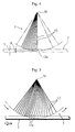
- FIG 1 and Figure 2 are showing an embodiment of a dust removing system according to the present invention, and this dust removing system is possessed with a dust removing head 1, a blower unit (not shown) and a traveler means (not shown) which makes work 2 traverse toward arrow A as the work 2 is arranged to be close to the head 1.
- the dust removing head 1 is comprising an air sucking chamber 4 having an air sucking opening 3 which opens at a position near the work 2, a rotating brushroll 5 disposed inside the air sucking chamber 4 slidable on the work 2, and a nozzle 6 which sucks and removes dust R adhered to the rotating brushroll 5.
- the dust removing head 1 possesses a casing 7 which is long in a width direction of the work 2, and inside the casing 7 the air sucking chamber 4 is formed corresponding to a substantially whole longitudinal length of the casing 7.
- the slit-like air sucking opening 3 having a longitudinal length L longer than a width Wa of the work 2 is formed.
- One end of an air sucking passage not shown in the attached drawings is connected to the air sucking chamber 4, and a blower unit which sucks air in the air sucking chamber 4 is connected to other end of the air sucking passage.
- a blower unit which sucks air in the air sucking chamber 4 is connected to other end of the air sucking passage.
- the rotating brushroll 5 is provided to be rotatable on axis M which is parallel to the slitted air sucking opening 3 inside the air sucking chamber 4 of the casing 7, and the brushroll 5 is rotated by a rotation driving means not shown in the attached drawings toward arrow F in Figure 1. With this rotating brushroll 5, the dust R adhered to a surface of the work 2 is wiped off.
- Nozzle 6 is stuck to an under surface of a partition wall 8 which is provided above the brushroll 5 in the air sucking chamber 4.
- the nozzle 6 has a slit hole 10 extended corresponding to a whole axial length of the brushroll 5.
- the nozzle 6 is possessed with a pair of blade portions 21 having concave face portions 20 which are formed on edges of end portions of outer faces thereof. Tip portions of the blade portions 21 are tip thin portions 22. Between inner faces of the pair of blade portions 21 opposing each other, a slit hole 10 extended corresponding to the whole axial length of the axis M of the brushroll 5 is formed.
- An end of nozzle 6 extended corresponding to the whole axial length of the axis M is arranged to be close to or contact with a circumferential face of the brushroll 5.
- a plurality of air passage slits 9 are provided on the partition wall 8 in the air sucking chamber 4, and one of said air passage slits 9 communicates the slit hole 10 of the nozzle 6.
- a diameter D of the rotating brushroll 5 and an inner width W parallel to a traveling direction of the work 2 of the air sucking chamber 4 are arranged to be D ⁇ W ⁇ (D+20mm). Therefore a space between the rotating brushroll 5 and an inner wall surface of the air sucking chamber 4 is possible to be smaller, and air inside the air sucking chamber 4 can flows at high speed, hereby dust R sucked in the air sucking chamber 4 can quickly flow into the air sucking passage, and the dust R can be prevented not to remain in the air sucking chamber 4, and readhering of the dust R to the work 2 can be also prevented.
- the diameter D and the inner width W are arranged to be (D+3mm) ⁇ W ⁇ (D+10mm), and the air inside the air sucking chamber 4 flows still more smoothly and at higher speed than the case arranged to be D ⁇ W ⁇ (D+20mm), therefore a possibility of the dust R remaining in the air sucking chamber 4 can be prevented.
- D > W the brushroll 5 contacts the inner wall surface of the air sucking chamber 4, and no space exist between the brushroll 5 and the inner wall surface of the air sucking chamber 4. Therefore a velocity of the air flow inside the air sucking chamber 4 is considerably lowered and power of sucking dust R of the dust removing head 1 will lose.
- W > (D+20mm) a space between the brushroll 5 and the inner wall surface of the air sucking chamber 4 becomes too large, and a velocity of the air flow inside the air sucking chamber 4 becomes lower.
- Air passes between divisional walls 11 which form an air sucking opening 3 and a work 2 is arranged to be at a velocity V of 50 to 60 m/s. Therefore dust R is removed from the work 2 still more effectively and is sucked into the air sucking chamber 4 for certain. Furthermore dust R adhered to a work 2 which is difficult to be exfoliated depending on quality of a material of the work 2 by a conventional dust removing system is possible to be removed with the dust removing system of the present invention in some cases.
- a velocity of air flow V is arranged to be below 50 m/s, dust R swept out by the brushroll 5 is possible to go outside through a space between partition walls 11 and a surface of the work 2. Even if a velocity of air flow V is more than 60 m/s, an efficiency of removing dust R does not change very much.
- a rotating brushroll 5 is arranged to rotate within a range of 1600 to 3000 r.p.m.. Therefore dust R adhered to the work 2 is effectively removed and a possibility of the work 2 to be scratched by the brushroll 5 can be prevented. If rotation of the brushroll 5 is below a range of 1600 r.p.m., dust R stuck strongly to the work 2 may not be removed in some cases. If rotation of the brushroll 5 is above a range of 3000 r.p.m., a surface of work 2 is possible to be scratched and damaged by the brushroll 5.
- a length B of bristle end portions 12a among brush bristles 12 of said rotating brushroll 5 contactable to the surface of the work 2 and a thickness T of said work 2 are arranged to be 0 ⁇ B ⁇ T. Therefore while this dust removing system is working, as shown in Figure 5, each of the brush end portions 12a slides surely on the surface of the work 2 in a condition that the brush bristle 12 is slightly bent and is moderately stored elastic energy. For this reason dust adhered to the work 2 is removed still more surely, and the work 2 can be prevented to be damaged. If a length B of the bristle end portion 12a is arranged to be 0 > B, i. e.
- the brushroll 5 will not have a function of removing dust. If B > T, the brush bristle 12 bends largely and hits and scratches the surface of the work 2 hardly.
- dust R adhered to the work 2 is removed surely and efficiently by the rotating brushroll 5 of the present dust removing system. Moreover dust R adhered to the brushroll 5 is removed by applying the nozzle 6, and the dust R adhered to the work 2 again which is removed once from the work 2 is possible to be prevented. Especially, for example, sticky dust, dust stuck in the work 2, fluff of the end rim of the work 2 (in case the work 2 is paper) are removed effectively.
- the dust removing head 1 of the dust removing system can be prevented to be dirty. That is to say, a space between the rotating brushroll 5 and an inner wall surface of an air sucking chamber 4 becomes smaller than that of the conventional dust removing system, and air inside the air sucking chamber 4 flows at high speed and dust R sucked in the air sucking chamber 4 can quickly flow into the air sucking passage. Therefore the dust R is prevented not to remain in the air sucking chamber 4 after an operation of the dust removing system. That is to say, the dust R is prevented not to remain in the rotating brushroll 5 and the inner wall surface of the air sucking chamber 4. Therefore the dust removing head 1 can be used for a long term without cleaning, and a frequency of cleaning and exchanging of the brushroll 5 can be decreased. In consequence, maintenance of the dust removing system would be easy and a running cost would be decreased at the same time.
- the brush bristle 5 can be made of, for example, polyamide resin, acrylic resin, metal, conductive fiber, but it is possible to be made of other materials.
- the work 2 which dust is removed therefrom can be, for example, paper, film or other materials.
- FIG. 6 shows another embodiment of the present invention.
- This dust removing system possesses first and second air discharging chambers 15, 16 arranged on an upstream side H and a downstream side J of an air sucking opening 3 of an air sucking chamber 4 and are provided with first and second ultrasonic nozzles 13, 14 which respectively change air to air knife K including ultrasonic pressure wave P and blow the air knife K against said work 2.
- Divisional walls 11 divide inside a casing 7 of a dust removing head 1 into the air sucking chamber 4 and the first and second discharging chambers 15, 16 on the upstream side H and the downstream side J of said air discharging chamber 4. Structures of rest of parts of this embodiment according to the present invention are almost same as those shown in Figure 1 to 5.
- the first and second air discharging chambers 15, 16 are provided with air from a blower unit not shown in the attached drawings through an air discharging passage not shown in the attached drawings.
- the air passes the first and second ultrasonic nozzle 13, 14, and becomes air knife K including ultrasonic pressure wave P and blown against a work 2. After that the air knife K is sucked in the air sucking chamber 4 together with the dust R, and the air goes back to said blower unit through an air sucking passage.
- an ultrasonic pressure wave P destroys a boundary layer 25 and an air knife K directly hits a surface of a work 2 and dust R can be exfoliated effectively. Therefore two kinds of dust removing operation which are of the brushroll 5 and of the air knife K including the ultrasonic pressure wave P, the dust R adhered to the work 2 can be removed still more surely. Especially, for example, adhesive dust, dust stuck in the work 2, fluff on an end rim of the work 2 (if the work 2 is paper) are removed effectively.
- FIG. 9 shows further embodiment of the present invention.
- the dust removing system possesses an air sucking chamber 17 arranged on a downstream side J of an air sucking chamber 4, and first and second air discharging chambers 15, 16 arranged on the downstream side J of said air sucking chamber 4 and provided with first and second ultrasonic nozzles 13, 14 which blow air knife K including ultrasonic pressure wave P against a work 2 on an upstream side H and a downstream side J of said air sucking chamber 17.
- the air knife K including the ultrasonic pressure wave P blown from the first and second ultrasonic nozzles 13, 14 on the downstream side J of the air sucking chamber 4 is possible to strongly suck and remove dust R remained in the work 2.
- the dust R adhered to the work 2 is removed by two steps of dust removing operations which are operations of the brushroll 5 and the air knife K on the downstream side of the air sucking chamber 4 including the ultrasonic pressure wave P. The dust can be removed still more surely by two steps of the dust removing operation.
- FIG 10 shows still another embodiment of the present invention.
- a casing 7 is possessed with partition walls 11 wherein (for example) blade edge portions 30 having triangular cross sections are obliquely formed on lower end edges thereof (as shown in Figure 10), and a gap between the lower end edge of the partition wall 11 ( i. e. the blade edge portion 30) and (an outer circumferential face of) the brushroll 5 is reduced. Therefore a velocity of air flows in the gap between the lower end edge of the partition wall 11 (i.e. the blade edge portion 30) and the outer circumferential face of the brushroll 5 is increased, and fine dust R separated from the surface of the work 2 can be sucked into the air sucking chamber 4 for certain.
Landscapes
- Cleaning In General (AREA)
- Paper (AREA)
- Coating Apparatus (AREA)
Applications Claiming Priority (3)
| Application Number | Priority Date | Filing Date | Title |
|---|---|---|---|
| JP15905796 | 1996-05-29 | ||
| JP159057/96 | 1996-05-29 | ||
| JP08159057A JP3122370B2 (ja) | 1996-05-29 | 1996-05-29 | 除塵装置 |
Publications (3)
| Publication Number | Publication Date |
|---|---|
| EP0810039A2 true EP0810039A2 (fr) | 1997-12-03 |
| EP0810039A3 EP0810039A3 (fr) | 1998-11-04 |
| EP0810039B1 EP0810039B1 (fr) | 2002-01-23 |
Family
ID=15685286
Family Applications (1)
| Application Number | Title | Priority Date | Filing Date |
|---|---|---|---|
| EP97108466A Expired - Lifetime EP0810039B1 (fr) | 1996-05-29 | 1997-05-26 | Système d'enlevage de poussière |
Country Status (6)
| Country | Link |
|---|---|
| EP (1) | EP0810039B1 (fr) |
| JP (1) | JP3122370B2 (fr) |
| KR (1) | KR100267630B1 (fr) |
| CN (1) | CN1182925C (fr) |
| DE (1) | DE69709984T2 (fr) |
| TW (1) | TW327140B (fr) |
Cited By (22)
| Publication number | Priority date | Publication date | Assignee | Title |
|---|---|---|---|---|
| DE19838757C1 (de) * | 1998-08-26 | 1999-12-30 | Abb Patent Gmbh | Verfahren zum Reinigen eines Werkstückträgers |
| DE10018388C1 (de) * | 2000-04-13 | 2002-01-03 | Airbus Gmbh | Vorrichtung zum Reinigen von Bauteiloberflächen, insbesondere in Bereichen von Verbindungselementen |
| DE10302127A1 (de) * | 2002-01-21 | 2003-11-20 | Honda Motor Co Ltd | Staubentfernungsvorrichtung |
| WO2005049238A1 (fr) * | 2003-11-21 | 2005-06-02 | Nix, Inc. | Extracteur de poussiere et son procede d'extraction |
| WO2007059919A2 (fr) * | 2005-11-22 | 2007-05-31 | Robo Paper B.V. | Dispositif et procede pour nettoyer une bande de matiere rotative |
| EP2037037A1 (fr) * | 2007-08-13 | 2009-03-18 | Equitan S.r.l. | Dispositif pour enlever des objets résiduels d'une surface d'une couche flexible, mince |
| FR2931712A1 (fr) * | 2008-06-02 | 2009-12-04 | Bosch Gmbh Robert | Dispositif motorise de nettoyage d'au moins un creuset d'une installation de brasage |
| WO2010140967A1 (fr) * | 2009-06-03 | 2010-12-09 | Leif Yxfeldt | Procédé et dispositif de traitement de surfaces |
| CN102319712A (zh) * | 2011-08-01 | 2012-01-18 | 广东润成创展木业有限公司 | 木门涂装用环保型除尘室 |
| CN105935660A (zh) * | 2016-06-30 | 2016-09-14 | 务川务欣米业有限责任公司 | 一套大米除尘分级系统 |
| EP3626356A1 (fr) * | 2018-09-18 | 2020-03-25 | Kabushiki Kaisha Toshiba | Tête de nettoyage, appareil de suppression et procédé de suppression |
| CN111335009A (zh) * | 2020-03-31 | 2020-06-26 | 天翊(江门)智能装备有限公司 | 一种全自动布料除尘设备 |
| CN112845207A (zh) * | 2020-12-23 | 2021-05-28 | 海南红塔卷烟有限责任公司 | 非标纸箱上下面贴标机 |
| EP3686324A4 (fr) * | 2017-09-20 | 2021-07-07 | Kabushiki Kaisha Toshiba | Appareil de filage |
| CN113275289A (zh) * | 2021-06-10 | 2021-08-20 | 吴新茂 | 一种节能型汽车散热器清洁设备 |
| US11141759B2 (en) | 2017-06-13 | 2021-10-12 | Hymmen GmbH Maschinen- und Anlagesbas | Method and apparatus for producing a decorative surface |
| CN113908936A (zh) * | 2021-10-11 | 2022-01-11 | 常州智砼绿色建筑科技有限公司 | 一种建筑垃圾用粉碎机 |
| CN114643217A (zh) * | 2022-03-21 | 2022-06-21 | 马鞍山市粤美金属制品科技实业有限公司 | 压缩机轴承配装检测装置 |
| US11559824B2 (en) | 2019-05-03 | 2023-01-24 | Hymmen Gmbh Maschinen-Und Anlagenbau | Method for producing a structure on a surface |
| GB2618595A (en) * | 2022-05-12 | 2023-11-15 | Meech Static Eliminators Ltd | Apparatus and method for web cleaning |
| NL2033591B1 (en) * | 2022-11-22 | 2024-05-30 | Besi Netherlands Bv | Cleaning unit for a mould for encapsulating electronic components, moulding system and method for encapsulating electronic components |
| WO2024188891A1 (fr) * | 2023-03-10 | 2024-09-19 | Wandres Gmbh Micro-Cleaning | Dispositif de nettoyage, procédé de nettoyage et utilisation d'un dispositif de nettoyage pour surfaces à déplacement rapide |
Families Citing this family (30)
| Publication number | Priority date | Publication date | Assignee | Title |
|---|---|---|---|---|
| WO2006029471A1 (fr) * | 2004-09-17 | 2006-03-23 | Synergetic Proprietary Limited | Appareil et procede de depoussierage |
| DE102007028341A1 (de) | 2007-06-15 | 2008-12-18 | Robo Paper B.V. | Vorrichtung und Verfahren zum Reinigen eines umlaufenden Bahnelementes |
| JP5310117B2 (ja) * | 2009-03-06 | 2013-10-09 | 王子ホールディングス株式会社 | 除塵装置 |
| JPWO2011039972A1 (ja) * | 2009-10-02 | 2013-02-21 | シャープ株式会社 | 清掃ノズル及びそれを備えた塵埃除去装置 |
| DE102010054813B4 (de) * | 2010-12-16 | 2012-07-26 | Karl W. Niemann Gmbh & Co. Kg | Verfahren und Vorrichtung zum Kaschieren einer Substratplatte mit einer Kunststofffolie |
| NL2007110C2 (nl) * | 2011-07-14 | 2013-01-15 | Fico Bv | Inrichting voor het reinigen van een omhulinrichting voor elektronische componenten. |
| CN102715874A (zh) * | 2012-06-07 | 2012-10-10 | 杜爵伟 | 地面清洁器 |
| CN202725553U (zh) * | 2012-07-09 | 2013-02-13 | 深圳市华星光电技术有限公司 | 清洁装置 |
| JP6058312B2 (ja) * | 2012-08-06 | 2017-01-11 | ヒューグル開発株式会社 | クリーニングヘッド |
| CN103100538A (zh) * | 2012-12-13 | 2013-05-15 | 吴江忆久纺织有限公司 | 纺织车间用吸尘装置 |
| CN103272817B (zh) * | 2013-05-29 | 2015-09-02 | 广东东睦新材料有限公司 | 一种粉末冶金用除尘装置 |
| CN103521479B (zh) | 2013-09-27 | 2016-03-30 | 京东方科技集团股份有限公司 | 清洁装置及直线涂布机 |
| CN104148306A (zh) * | 2014-07-30 | 2014-11-19 | 熊丹 | 太阳能电池除尘设备 |
| CN105032841B (zh) * | 2015-07-23 | 2017-07-14 | 熊一凡 | 用于清理有害粉尘的高压气流手 |
| CN105149250A (zh) * | 2015-09-08 | 2015-12-16 | 宁国市南方耐磨材料有限公司 | 一种圆球形耐磨钢球清杂装置 |
| CN105834137B (zh) * | 2016-05-31 | 2018-03-16 | 圣象实业(江苏)有限公司 | 地板除尘清洁装置 |
| CN107282488A (zh) * | 2017-07-18 | 2017-10-24 | 合肥余塝电子商务有限公司 | 一种电子电器分级除尘装置 |
| CN107874704B (zh) * | 2017-12-05 | 2023-08-15 | 江苏美的清洁电器股份有限公司 | 刮板、具有该刮板的地刷、以及具有该地刷的吸尘器 |
| CN109331574B (zh) * | 2018-11-27 | 2021-06-18 | 西安科技大学 | 适用于气体粉尘爆炸密闭容器的排气除尘设备及方法 |
| CN110077883B (zh) * | 2019-04-19 | 2020-09-08 | 浙江常鑫纺织品有限公司 | 一种服装辅料定型整理装置 |
| CN109877469B (zh) * | 2019-04-26 | 2020-11-20 | 郑微丹 | 用于激光切割的除尘机构 |
| CN110624867B (zh) * | 2019-10-23 | 2021-08-06 | 郑州财经学院 | 一种纺织用毛刷辊的清洁装置 |
| CN112170310A (zh) * | 2020-09-15 | 2021-01-05 | 国网山东省电力公司平阴县供电公司 | 一种机柜除尘装置 |
| JP2022069983A (ja) * | 2020-10-26 | 2022-05-12 | 株式会社東芝 | 電界紡糸装置、及び、電界紡糸ヘッドの清掃方法 |
| CN112452928A (zh) * | 2020-11-02 | 2021-03-09 | 王宝根 | 一种硅片自动除尘装置 |
| CN112547621B (zh) * | 2020-11-20 | 2022-04-19 | 贵州黔北粮仓米业有限公司 | 一种智能化大米加工设备 |
| KR102578251B1 (ko) * | 2021-02-10 | 2023-09-13 | (주)필옵틱스 | Oled 플렉서블 디스플레이 필름용 커팅 작업대 클린닝 장치 |
| CN113154862B (zh) * | 2021-02-26 | 2022-07-15 | 东莞汇和电子有限公司 | 一种电子线路板装配活塞干燥风刀 |
| CN114542416B (zh) * | 2022-02-23 | 2023-10-27 | 吴小龙 | 一种具有防污功能的皮带空压机 |
| CN117019772B (zh) * | 2023-10-08 | 2024-02-23 | 宁德时代新能源科技股份有限公司 | 除尘机构、极片除尘装置及电池生产系统 |
Citations (9)
| Publication number | Priority date | Publication date | Assignee | Title |
|---|---|---|---|---|
| US3986223A (en) * | 1973-05-21 | 1976-10-19 | Herbert Products, Inc. | Surface cleaning device |
| US4282626A (en) * | 1977-10-17 | 1981-08-11 | California Institute Of Technology | Cleaning devices |
| CH654753A5 (en) * | 1982-01-21 | 1986-03-14 | Fredy Truniger | Method and apparatus for cleaning the outside of an approximately cylindrical filter element |
| US4706325A (en) * | 1986-07-09 | 1987-11-17 | Michelson Manfred G | Film cleaner |
| US4996746A (en) * | 1988-08-23 | 1991-03-05 | Rieter Machine Works, Ltd. | Flat cleaning apparatus for a card |
| JPH0549826A (ja) * | 1991-08-12 | 1993-03-02 | Seidensha:Kk | フイルター洗浄装置 |
| EP0565811A1 (fr) * | 1992-04-13 | 1993-10-20 | Shinko Co., Ltd. | Système d'enlevage de poussière pour des corps comme des panneaux |
| EP0640411A1 (fr) * | 1993-08-31 | 1995-03-01 | Shinko Co., Ltd. | Système d'enlevage de poussière |
| EP0682992A2 (fr) * | 1994-05-16 | 1995-11-22 | Valmet Paper Machinery Inc. | Méthode et dispositif pour l'enlèvement et la collection de poussière séparée d'une bande pour une machine à papier ou une machine de finition du papier |
Family Cites Families (1)
| Publication number | Priority date | Publication date | Assignee | Title |
|---|---|---|---|---|
| JPH0636906B2 (ja) * | 1988-05-11 | 1994-05-18 | 株式会社伸興 | 除塵装置 |
-
1996
- 1996-05-29 JP JP08159057A patent/JP3122370B2/ja not_active Expired - Lifetime
-
1997
- 1997-05-12 TW TW086106280A patent/TW327140B/zh not_active IP Right Cessation
- 1997-05-26 EP EP97108466A patent/EP0810039B1/fr not_active Expired - Lifetime
- 1997-05-26 DE DE69709984T patent/DE69709984T2/de not_active Expired - Lifetime
- 1997-05-29 KR KR1019970021488A patent/KR100267630B1/ko active IP Right Grant
- 1997-05-29 CN CNB971054193A patent/CN1182925C/zh not_active Expired - Lifetime
Patent Citations (9)
| Publication number | Priority date | Publication date | Assignee | Title |
|---|---|---|---|---|
| US3986223A (en) * | 1973-05-21 | 1976-10-19 | Herbert Products, Inc. | Surface cleaning device |
| US4282626A (en) * | 1977-10-17 | 1981-08-11 | California Institute Of Technology | Cleaning devices |
| CH654753A5 (en) * | 1982-01-21 | 1986-03-14 | Fredy Truniger | Method and apparatus for cleaning the outside of an approximately cylindrical filter element |
| US4706325A (en) * | 1986-07-09 | 1987-11-17 | Michelson Manfred G | Film cleaner |
| US4996746A (en) * | 1988-08-23 | 1991-03-05 | Rieter Machine Works, Ltd. | Flat cleaning apparatus for a card |
| JPH0549826A (ja) * | 1991-08-12 | 1993-03-02 | Seidensha:Kk | フイルター洗浄装置 |
| EP0565811A1 (fr) * | 1992-04-13 | 1993-10-20 | Shinko Co., Ltd. | Système d'enlevage de poussière pour des corps comme des panneaux |
| EP0640411A1 (fr) * | 1993-08-31 | 1995-03-01 | Shinko Co., Ltd. | Système d'enlevage de poussière |
| EP0682992A2 (fr) * | 1994-05-16 | 1995-11-22 | Valmet Paper Machinery Inc. | Méthode et dispositif pour l'enlèvement et la collection de poussière séparée d'une bande pour une machine à papier ou une machine de finition du papier |
Non-Patent Citations (1)
| Title |
|---|
| PATENT ABSTRACTS OF JAPAN vol. 17, no. 355 (C-1079), 6 July 1993 & JP 05 049826 A (SEIDENSHA), 2 March 1993 * |
Cited By (36)
| Publication number | Priority date | Publication date | Assignee | Title |
|---|---|---|---|---|
| DE19838757C1 (de) * | 1998-08-26 | 1999-12-30 | Abb Patent Gmbh | Verfahren zum Reinigen eines Werkstückträgers |
| DE10018388C1 (de) * | 2000-04-13 | 2002-01-03 | Airbus Gmbh | Vorrichtung zum Reinigen von Bauteiloberflächen, insbesondere in Bereichen von Verbindungselementen |
| DE10302127A1 (de) * | 2002-01-21 | 2003-11-20 | Honda Motor Co Ltd | Staubentfernungsvorrichtung |
| US7017226B2 (en) | 2002-01-21 | 2006-03-28 | Honda Giken Kogyo Kabushiki Kaisha | Dust removal apparatus |
| WO2005049238A1 (fr) * | 2003-11-21 | 2005-06-02 | Nix, Inc. | Extracteur de poussiere et son procede d'extraction |
| WO2007059919A3 (fr) * | 2005-11-22 | 2007-11-29 | Robo Paper B V | Dispositif et procede pour nettoyer une bande de matiere rotative |
| WO2007059919A2 (fr) * | 2005-11-22 | 2007-05-31 | Robo Paper B.V. | Dispositif et procede pour nettoyer une bande de matiere rotative |
| EP2037037A1 (fr) * | 2007-08-13 | 2009-03-18 | Equitan S.r.l. | Dispositif pour enlever des objets résiduels d'une surface d'une couche flexible, mince |
| FR2931712A1 (fr) * | 2008-06-02 | 2009-12-04 | Bosch Gmbh Robert | Dispositif motorise de nettoyage d'au moins un creuset d'une installation de brasage |
| EP2130613A1 (fr) * | 2008-06-02 | 2009-12-09 | Robert Bosch GmbH | Dispositif motorisé de nettoyage d'au moins un creuset d'une installation de brasage |
| WO2010140967A1 (fr) * | 2009-06-03 | 2010-12-09 | Leif Yxfeldt | Procédé et dispositif de traitement de surfaces |
| CN102458696A (zh) * | 2009-06-03 | 2012-05-16 | L·伊西费尔特 | 用于处理表面的方法和设备 |
| CN102319712A (zh) * | 2011-08-01 | 2012-01-18 | 广东润成创展木业有限公司 | 木门涂装用环保型除尘室 |
| CN105935660A (zh) * | 2016-06-30 | 2016-09-14 | 务川务欣米业有限责任公司 | 一套大米除尘分级系统 |
| CN105935660B (zh) * | 2016-06-30 | 2018-05-22 | 务川务欣米业有限责任公司 | 一套大米除尘分级系统 |
| US11717851B2 (en) | 2017-06-13 | 2023-08-08 | Hymmen GmbH Maschinen—und Anlagenbau | Method and apparatus for producing a decorative workpiece and workpiece |
| US11420229B2 (en) | 2017-06-13 | 2022-08-23 | Hymmen GmbH Maschinen—und Anlagenbau | Method and apparatus for producing a decorative surface |
| US12090511B2 (en) | 2017-06-13 | 2024-09-17 | Hymmen GmbH Maschinen—und Anlagenbau | Method and apparatus for producing a decorative surface |
| US11883843B2 (en) | 2017-06-13 | 2024-01-30 | Hymmen Gmbh Maschinen-Und Anlagenbau | Method for producing a structured surface |
| US11141759B2 (en) | 2017-06-13 | 2021-10-12 | Hymmen GmbH Maschinen- und Anlagesbas | Method and apparatus for producing a decorative surface |
| US11717850B2 (en) | 2017-06-13 | 2023-08-08 | Hymmen Gmbh Maschinen-Und Anlagenbau | Method and apparatus for producing a decorative workpiece and workpiece |
| US11511318B2 (en) | 2017-06-13 | 2022-11-29 | Hymmen GmbH Maschinen- und Anlagenbau | Method and apparatus for producing a decorative workpiece and workpiece |
| EP3686324A4 (fr) * | 2017-09-20 | 2021-07-07 | Kabushiki Kaisha Toshiba | Appareil de filage |
| US11559134B2 (en) | 2018-09-18 | 2023-01-24 | Kabushiki Kaisha Toshiba | Cleaner head, removing apparatus, and removing method |
| EP3626356A1 (fr) * | 2018-09-18 | 2020-03-25 | Kabushiki Kaisha Toshiba | Tête de nettoyage, appareil de suppression et procédé de suppression |
| US11559824B2 (en) | 2019-05-03 | 2023-01-24 | Hymmen Gmbh Maschinen-Und Anlagenbau | Method for producing a structure on a surface |
| CN111335009A (zh) * | 2020-03-31 | 2020-06-26 | 天翊(江门)智能装备有限公司 | 一种全自动布料除尘设备 |
| CN112845207A (zh) * | 2020-12-23 | 2021-05-28 | 海南红塔卷烟有限责任公司 | 非标纸箱上下面贴标机 |
| CN113275289A (zh) * | 2021-06-10 | 2021-08-20 | 吴新茂 | 一种节能型汽车散热器清洁设备 |
| CN113908936A (zh) * | 2021-10-11 | 2022-01-11 | 常州智砼绿色建筑科技有限公司 | 一种建筑垃圾用粉碎机 |
| CN114643217A (zh) * | 2022-03-21 | 2022-06-21 | 马鞍山市粤美金属制品科技实业有限公司 | 压缩机轴承配装检测装置 |
| GB2618595A (en) * | 2022-05-12 | 2023-11-15 | Meech Static Eliminators Ltd | Apparatus and method for web cleaning |
| WO2023218173A1 (fr) * | 2022-05-12 | 2023-11-16 | Meech Static Eliminators Limited | Appareil et procédé de nettoyage de bande |
| NL2033591B1 (en) * | 2022-11-22 | 2024-05-30 | Besi Netherlands Bv | Cleaning unit for a mould for encapsulating electronic components, moulding system and method for encapsulating electronic components |
| WO2024112192A1 (fr) * | 2022-11-22 | 2024-05-30 | Besi Netherlands B.V. | Unité de nettoyage pour un moule d'encapsulation de composants électroniques, système de moulage et procédé d'encapsulation de composants électroniques |
| WO2024188891A1 (fr) * | 2023-03-10 | 2024-09-19 | Wandres Gmbh Micro-Cleaning | Dispositif de nettoyage, procédé de nettoyage et utilisation d'un dispositif de nettoyage pour surfaces à déplacement rapide |
Also Published As
| Publication number | Publication date |
|---|---|
| TW327140B (en) | 1998-02-21 |
| CN1182925C (zh) | 2005-01-05 |
| DE69709984D1 (de) | 2002-03-14 |
| DE69709984T2 (de) | 2002-09-26 |
| CN1166386A (zh) | 1997-12-03 |
| JP3122370B2 (ja) | 2001-01-09 |
| KR100267630B1 (ko) | 2000-10-16 |
| EP0810039B1 (fr) | 2002-01-23 |
| JPH09314072A (ja) | 1997-12-09 |
| EP0810039A3 (fr) | 1998-11-04 |
| KR970073747A (ko) | 1997-12-10 |
Similar Documents
| Publication | Publication Date | Title |
|---|---|---|
| EP0810039A2 (fr) | Système d'enlevage de poussière | |
| US5466298A (en) | Web cleaning method | |
| US20090165238A1 (en) | Web substrate cleaning systems & methods | |
| EP0139211B1 (fr) | Buse de succion | |
| CN1066647C (zh) | 在轧机机架的出料装置中用于缝隙的无接触密封装置 | |
| US3986223A (en) | Surface cleaning device | |
| US7147724B2 (en) | Cleaning device for a longitudinal cutting device and method for cleaning the device | |
| US5241908A (en) | Washing device of a printing device | |
| US3436265A (en) | Pressure gradient web cleaning method | |
| JP2001038880A (ja) | ダンボール紙印刷機用除塵装置 | |
| JP3400675B2 (ja) | 除塵装置 | |
| CN208643382U (zh) | 辊面清洁机构及集流体打孔设备 | |
| JPH05269452A (ja) | シート状物用除塵装置 | |
| JPH07267420A (ja) | シート搬送ロールの掃除装置 | |
| JPH0857759A (ja) | バリ取り装置 | |
| JP4256510B2 (ja) | サンドブラスト加工における被加工物のクリーニングユニット | |
| CN102039613B (zh) | 除尘装置 | |
| GB2172014A (en) | Process and apparatus for removing a film of material clinging to moving strip material | |
| US4889564A (en) | Magnetic disk cleaning method and apparatus | |
| JPH06115057A (ja) | シリンダ洗浄装置 | |
| JPH06165960A (ja) | 吸引ノズル、超音波除塵ノズル及び超音波除塵装置 | |
| JP3541308B2 (ja) | シャワー洗浄装置 | |
| JPH0623697A (ja) | ダスト捕集装置 | |
| JPH0639420A (ja) | 帯板のプロセスラインのロール手入れ装置 | |
| JPH0938608A (ja) | 除塵装置 |
Legal Events
| Date | Code | Title | Description |
|---|---|---|---|
| PUAI | Public reference made under article 153(3) epc to a published international application that has entered the european phase |
Free format text: ORIGINAL CODE: 0009012 |
|
| AK | Designated contracting states |
Kind code of ref document: A2 Designated state(s): DE FR GB IT |
|
| PUAL | Search report despatched |
Free format text: ORIGINAL CODE: 0009013 |
|
| AK | Designated contracting states |
Kind code of ref document: A3 Designated state(s): DE FR GB IT |
|
| 17P | Request for examination filed |
Effective date: 19981223 |
|
| 17Q | First examination report despatched |
Effective date: 20000608 |
|
| GRAG | Despatch of communication of intention to grant |
Free format text: ORIGINAL CODE: EPIDOS AGRA |
|
| GRAG | Despatch of communication of intention to grant |
Free format text: ORIGINAL CODE: EPIDOS AGRA |
|
| GRAH | Despatch of communication of intention to grant a patent |
Free format text: ORIGINAL CODE: EPIDOS IGRA |
|
| GRAH | Despatch of communication of intention to grant a patent |
Free format text: ORIGINAL CODE: EPIDOS IGRA |
|
| GRAA | (expected) grant |
Free format text: ORIGINAL CODE: 0009210 |
|
| REG | Reference to a national code |
Ref country code: GB Ref legal event code: IF02 |
|
| AK | Designated contracting states |
Kind code of ref document: B1 Designated state(s): DE FR GB IT |
|
| REF | Corresponds to: |
Ref document number: 69709984 Country of ref document: DE Date of ref document: 20020314 |
|
| ET | Fr: translation filed | ||
| PLBE | No opposition filed within time limit |
Free format text: ORIGINAL CODE: 0009261 |
|
| STAA | Information on the status of an ep patent application or granted ep patent |
Free format text: STATUS: NO OPPOSITION FILED WITHIN TIME LIMIT |
|
| 26N | No opposition filed | ||
| REG | Reference to a national code |
Ref country code: FR Ref legal event code: PLFP Year of fee payment: 20 |
|
| PGFP | Annual fee paid to national office [announced via postgrant information from national office to epo] |
Ref country code: DE Payment date: 20160523 Year of fee payment: 20 Ref country code: GB Payment date: 20160504 Year of fee payment: 20 |
|
| PGFP | Annual fee paid to national office [announced via postgrant information from national office to epo] |
Ref country code: FR Payment date: 20160429 Year of fee payment: 20 Ref country code: IT Payment date: 20160520 Year of fee payment: 20 |
|
| REG | Reference to a national code |
Ref country code: DE Ref legal event code: R071 Ref document number: 69709984 Country of ref document: DE |
|
| REG | Reference to a national code |
Ref country code: GB Ref legal event code: PE20 Expiry date: 20170525 |
|
| PG25 | Lapsed in a contracting state [announced via postgrant information from national office to epo] |
Ref country code: GB Free format text: LAPSE BECAUSE OF EXPIRATION OF PROTECTION Effective date: 20170525 |