EP0809943B1 - Dispositif d'ébarbage du tabac pour une machine à fabriquer les cigarettes - Google Patents
Dispositif d'ébarbage du tabac pour une machine à fabriquer les cigarettes Download PDFInfo
- Publication number
- EP0809943B1 EP0809943B1 EP97108594A EP97108594A EP0809943B1 EP 0809943 B1 EP0809943 B1 EP 0809943B1 EP 97108594 A EP97108594 A EP 97108594A EP 97108594 A EP97108594 A EP 97108594A EP 0809943 B1 EP0809943 B1 EP 0809943B1
- Authority
- EP
- European Patent Office
- Prior art keywords
- disk
- shredded tobacco
- trimming
- tobacco layer
- peeling
- Prior art date
- Legal status (The legal status is an assumption and is not a legal conclusion. Google has not performed a legal analysis and makes no representation as to the accuracy of the status listed.)
- Expired - Lifetime
Links
- 241000208125 Nicotiana Species 0.000 title claims description 89
- 235000002637 Nicotiana tabacum Nutrition 0.000 title claims description 89
- 238000009966 trimming Methods 0.000 title claims description 76
- 238000004519 manufacturing process Methods 0.000 title claims description 16
- 235000019504 cigarettes Nutrition 0.000 title claims description 15
- 230000002093 peripheral effect Effects 0.000 claims description 27
- 230000032258 transport Effects 0.000 claims description 2
- 230000005540 biological transmission Effects 0.000 description 3
- 238000013467 fragmentation Methods 0.000 description 3
- 238000006062 fragmentation reaction Methods 0.000 description 3
- 239000002184 metal Substances 0.000 description 3
- 238000007790 scraping Methods 0.000 description 3
- 230000004048 modification Effects 0.000 description 2
- 238000012986 modification Methods 0.000 description 2
- 230000015572 biosynthetic process Effects 0.000 description 1
- 239000012634 fragment Substances 0.000 description 1
- 230000002452 interceptive effect Effects 0.000 description 1
- 239000002245 particle Substances 0.000 description 1
- 238000009751 slip forming Methods 0.000 description 1
- 238000011144 upstream manufacturing Methods 0.000 description 1
Images
Classifications
-
- A—HUMAN NECESSITIES
- A24—TOBACCO; CIGARS; CIGARETTES; SIMULATED SMOKING DEVICES; SMOKERS' REQUISITES
- A24C—MACHINES FOR MAKING CIGARS OR CIGARETTES
- A24C5/00—Making cigarettes; Making tipping materials for, or attaching filters or mouthpieces to, cigars or cigarettes
- A24C5/14—Machines of the continuous-rod type
- A24C5/18—Forming the rod
- A24C5/1842—Trimming devices
Definitions
- the present invention relates to a device for trimming a shredded tobacco layer sucked on a suction band according to the preamble of appended claim 1, thereby adjusting the thickness of the shredded tobacco layer when a tobacco rod is continuously formed in a cigarette manufacturing machine.
- EP-A-06 450 98 which comprises a trimming device and a peeling device in a cigarette manufacturing machine, said peeling device being formed as a cutting device which axis is parallel to the axis of the trimming device.
- GB-A-21 504 10 which includes a tobacco trimming apparatus , wherein the surplus of tobacco shreds is removed by short teeth which are machined into a slightly conical peripheral surface of a rotating disc.
- a trimming device for shredded tobacco layer has a trimming disks rotatably arranged under a suction band of a cigarette manufacturing machine, and a rotary brush of metal which rotates kept in contact with the lower surfaces of the trimming disks.
- the trimming disks and the rotary brush cooperate with each other to adjust a shredded tobacco layer sucked on the lower surface of the suction band to a predetermined thickness. More specifically, the shredded tobacco layer is adjusted to a thickness corresponding to a distance between the trimming disk and the suction band, and surplus shredded tobacco located under the trimming disks is removed by the rotary brush.
- the rotary brush has a plurality of scraping fins which are disposed spaced apart from one another on the peripheral surface of the rotary brush. Each scraping fin has a blade at the tip thereof. As the rotary brush rotates, each blade periodically comes in contact with the lower surfaces of the trimming disks. Thus, a portion of the shredded tobacco layer which would otherwise pass under the trimming disks, that is, the surplus shredded tobacco is scraped off by the fins of the rotary brush. The scraped-off shredded tobacco is thereafter collected and reused to form a shredded tobacco layer.
- traveling speed of the suction band that is, transportation speed of the shredded tobacco layer tends to be more and more increased in order to enhance productivity in manufacturing tobacco rod by the cigarette manufacturing machine.
- the rotary brush of the trimming device also needs to be rotated at high speed, in order to steadily adjust the thickness of the shredded tobacco layer.
- the object of the present invention is to provide a trimming device for shredded tobacco capable of reducing the fragmentation of the shredded tobacco and suitable for high speed operation of the cigarette manufacturing machine.
- a trimming device comprises: a trimming disk rotatably arranged in a vicinity of a suction band which forms and transports a shredded tobacco layer, the trimming disk being continuously cutting into the shredded tobacco layer on the suction band during the rotation of trimming disk, thereby dividing the shredded tobacco layer into a required layer portion and a surplus portion; and removing means for removing the surplus portion of the shredded tobacco layer in cooperation with the trimming disk.
- the removing means includes a rotatable peeler disk having a peeling blade formed at a peripheral edge of the peeler disk to extend continuously in a peripheral direction thereof and arranged to move keeping contact with a lower surface of the trimming disk, and a flat end face for guiding the removed surplus portion.
- the surplus portion of the shredded tobacco layer is removed by the peeling blade like peel is removed off. Further, the surplus shredded tobacco peeled off by the peeling blade is guided by the flat end face and discharged from the peripheral edge of the peeler disk. Therefore, the surplus shredded tobacco will not be subjected to excessively large impact, and the fragmentation of the shredded tobacco is largely reduced. As a result, rate of reuse of the surplus shredded tobacco collected is increased, and productivity of the cigarette manufacturing machine can be enhanced.
- the peeler disk further comprises a taper surface forming the periphery of the peeler disk and arranged to be in line contact with the lower surface of the trimming disk, and the peripheral edge of the large-diameter side of the taper surface is formed as the peeling blade.
- the shredded tobacco peeled off by the peeling blade is guided by the large-diameter end face of the peeler disk and discharged from the peripheral edge thereof.
- the peeling blade is so arranged as to pass through the shredded tobacco layer, moving in the direction obliquely crossing the transportation direction of the shredded tobacco layer. In this arrangement, the peeling blade can easily cut into the shredded tobacco.
- the taper surface of the peeler disk may be provided with a plurality of transverse recesses which are disposed equally spaced apart from one another in the peripheral direction of the peeler disk. In this case, even when the trimming disks have a plurality of pockets, the pockets do not interfere with the rotation of the peeler disk.
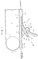
- Fig. 1 shows a part of a cigarette manufacturing machine including a device for trimming a shredded tobacco layer.
- the cigarette manufacturing machine is provided with an endless suction band 2, which is extended around a pair of band rollers 4.
- the suction band 2 travels at a constant speed in the direction indicated by an arrow A in Fig. 1 within a perpendicular plane. It is to be noted that only one of the band rollers 4 is shown in Fig. 1.
- the suction band 2 is disposed in a suction chamber 6.
- the suction chamber 6 generates an air flow flowing upward from under the suction band 2.
- a chimney (not shown) directly under the suction band 2.
- Shredded tobacco supplied into the chimney is blown up with air by sucking force of the suction chamber 6 and sucked onto the lower surface of the suction band 2 in the form of a layer.
- a shredded tobacco layer T L0 is formed on the portion of the suction band 2 which has passed through the chimney.
- the shredded tobacco layer T L0 is transported with the suction band 2, and then at the position of the band roller 4, taken off the suction band 2 by a shoe (a scraper) not shown and supplied on to paper in a wrapping section of the cigarette manufacturing machine.
- the trimming device 8 Under the suction band 2 is provided a trimming device 8 in the vicinity of one of the band rollers 4.
- the trimming device 8 has a pair of trimming disks 10 disposed on the left and right sides of the suction band 2 relative to the traveling direction of the suction band 2.
- the Trimming disks 10 are made of metal and disposed on the same horizontal plane. In Fig. 1, only an axis of a rotary shaft on which one of the trimming disks 10 is mounted is shown.
- the pair of trimming disks 10 are disposed on both sides of the suction band 2, and the peripheral edge portions of the trimming disks 10 are close to each other under the suction band 2, with a perpendicular plane including a center line of the suction band 2 sandwiched between the peripheral edge portions of the trimming disks 10.
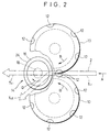
- the pair of trimming disks 10 are rotated in opposite directions. The directions of their rotations are indicated by arrows B in Fig. 2. It is to be noted that after coming close to each other, the peripheral edge portions of the trimming disks 10 move in the same direction with the transportation direction A of the aforementioned shredded tobacco layer T L0 .
- the pair of the trimming disks 10 have a plurality of pockets 12 at their peripheral portions, respectively (Fig. 1).
- the pockets 12 are disposed equally spaced apart from one another in the peripheral direction of each trimming disk 10. It is so provided that while the pair of trimming disks 10 are rotating, each pocket 12 of one of the trimming disks 10 periodically meets a corresponding pocket 12 of the other trimming disk 10 under the suction band 2.
- the trimming device further comprises a peeler disk 14 made of metal.
- the peeler disk 14 is rotatably provided directly under the pair of trimming disks 10. More specifically, the peeler disk 14 is disposed oblique to a horizontal plane, and an angle ⁇ formed by the peeler disk 14 and the trimming disks 10 is set to 15 ° ⁇ 45°, for example. It is to be noted the peeler disk 14 is so inclined that the upper portion of the peeler disk 14 is located at the upstream side relative to the transportation direction A of the shredded tobacco layer T L0 , while the lower portion thereof is at the downstream side. As seen in Fig. 1, the peeler disk 14 is trapezoidal in cross section and has a taper surface 16 on the periphery thereof.
- the taper surface 16 tapers toward the lower surface of the trimming disk 10. It is so arranged that the taper surface 16 is in line contact with the lower surfaces of the pair of trimming disks 10 at its upper portion. Therefore, as the peeler disk 14 rotates, the taper surface 16 moves keeping contact with the lower surfaces of the pair of trimming disks 10 in the area where the peripheral edge portions of the pair of the trimming disks 10 are close to each other.
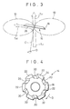
- the taper surface 16 moves in the direction intersecting the transportation direction A of the shredded tobacco layer T L0 . That is, as seen in Fig. 3, the axis of rotation C of the peeler disk 14 intersects the perpendicular plane including a transportation axis of the shredded tobacco layer T L at a predetermined angle.
- the peeler disk 14 is mounted on one end of a rotary shaft 18, while the other end of the rotary shaft 18 is connected to a power transmission system (not shown).
- a power transmission system (not shown).
- torque is supplied from the power transmission system to the rotary shaft 18, thereby to rotate the peeler disk 14 in the direction D.
- the power transmission system supplies torque also to the pair of band rollers 4 of the suction band 2 and the pair of trimming disks 10.
- Fig. 4 shows the peeler disk 14 in detail.
- the taper surface 16 of the peeler disk 14 is not a smooth continuous surface, but is formed with a plurality of transverse recesses 20.
- the transverse recesses 20 are disposed equally spaced apart from one another in the peripheral direction of the peeler disk 14, so that the taper surface 16 has a plurality of land portions 22.
- the trimming disks 10 have respectively six pockets 12, the taper surface 16 is formed with six transverse recesses 20 and six land portions 22.
- the transverse recesses 20 have bottom surface arranged on a same circular plane.
- each transverse recess 20 and the land portion 22 of the taper surface 16 pass the area where the peripheral edge portions of the pair of trimming disks 10 are close to each other, alternately and periodically. At that time, each transverse recess 20 periodically meets a corresponding pair of pockets 12 formed to the pair of trimming disks 10, respectively.
- the pair of trimming disks 10 can rotate without their pockets 12 interfering with the peeler disk 14. More specifically, in order to prevent the interference with the pockets 12, each transverse recess 20 is formed, as seen in Fig.
- each transverse recess 20 has a predetermined width in the peripheral direction of the peeler disk 14, and a depth equal to the distance between the upper surface of the trimming disk 10 and the lower surface of the pocket 12. The aforementioned oblique formation of each transverse recess 20 allows the transverse recess 20 to have a minimum width.
- the peripheral edge at the side of the large-diameter end face of the peeler disk 14 is formed as a peeling blade 24 continuously extending in the peripheral direction of the peeler disk 14. More specifically, the peeling blade 24 includes the edges of the land portions 22 and the edges defining the open ends of the transverse recesses 20. Therefore, the distance between the axis of the peeler disk 14 and the peeling blade 24 varies periodically in the peripheral direction of the peeler disk 14.
- the aforementioned pair of trimming disks 10 and the peeler disk 4 are supported in the manner that they can be moved in connection with each other in the perpendicular direction, or instead, the suction band 2 is so provided that a portion thereof located over the pair of trimming disks 10 can be raised and lowered.
- the distance between the suction band 2 and the pair of trimming disks10 is adjustable.
- the pair of trimming disks 10 and the peeler disk 14 are rotating.
- the peeler disk 14 rotates with its peeling blade 24 kept in contact with the lower surfaces of the peripheral edge portions of the trimming disks 10.
- the peripheral edge portions of the pair of trimming disks 10 cut into the shredded tobacco layer T L0 and divide the shredded tobacco layer T L0 into upper and lower portions.
- the peeling blade 24 of the peeler disk 14 which rotates keeping contact with the lower surfaces of the peripheral edge portions of the trimming disks 10 (including the lower surfaces of the pockets 12), scrapes the lower portion of the shredded tobacco layer T L0 off the lower surfaces of the trimming disks 10.
- the surplus portion of the shredded tobacco layer T L0 is removed from the shredded tobacco layer T L0 in the form of a layer, like peel is peeled off.
- the peeling blade 24 thereof is disposed oblique to the transportation direction of the shredded tobacco layer T L0 , the peeling blade 24 can easily cut into the shredded tobacco layer T L0 , and the surplus shredded tobacco is smoothly scraped off.
- the surplus shredded tobacco T LE is thereafter collected by collecting means (not shown) and reused to form a shredded tobacco layer T L0 .
- the shredded tobacco layer remaining on the lower surface of the suction band 2, that is, the trimmed shredded-tobacco layer T L1 is adjusted in its thickness correctly to the distance between the trimming disks 10 and the suction band 2.
- a pair of pockets 12 meet each other periodically in the shredded tobacco layer T L0 as mentioned above, so that thickened portions T LH having a thickness increased by an amount corresponding to the content of the pair of pockets 12 are periodically formed to the trimmed shredded-tobacco layer T L1 (Fig. 1).
- the thickened portion T LH are formed spaced apart from each other by a distance corresponding to twice a length of a cigarette, for example.
- the shredded tobacco layer T L1 is thereafter supplied from the suction band 2 to the wrapping section of the cigarette manufacturing machine as mentioned above.
- the shredded tobacco layer T L1 supplied to the wrapping section is wrapped in the paper (not shown) as known, whereby a tobacco rod is formed continuously.
- the formed tobacco rod is supplied from the wrapping section to a cutting section of the cigarette manufacturing machine, where the tobacco rod is cut at the center of each portion corresponding to the aforementioned thickened portion, thereby to be separated into double-cigarettes.
- the shredded tobacco layer T L0 is trimmed in the manner that the surplus shredded tobacco T LE is removed from the shredded tobacco layer T L0 like peel is peeled off. Therefore, the surplus shredded tobacco T LE will not be subjected to a large load. Further, since the surplus shredded tobacco T LE flows guided by the large-diameter end face 26 of the peeler disk 14, the surplus shredded tobacco T LE will not be subjected to a large impact. Furthermore, since the surplus shredded tobacco T LE is discharged downward from the periphery of the peeler disk 14, the surplus shredded tobacco T LE can be collected easily. Thus, the surplus shredded tobacco T LE can be well protected from fragmentation so that the rate of reuse of the surplus shredded tobacco T LE is enhanced, while the transportation speed of the shredded tobacco layer is allowed to be increased. Therefore, the production efficiency of tobacco rod can be enhanced.
- the present invention is not limited to the above described embodiment, but various modifications can be made thereto.
- the axis of rotation of the peeler disk 14 may extend within the perpendicular plane including the axis of the suction band 2.
- the peeling blade 24 of the peeler disk 14 moves in the direction orthogonal to the transportation direction A of the shredded tobacco layer T L1 and scrapes the surplus shredded tobacco off the lower surface of the trimming disks 10.
Landscapes
- Manufacturing Of Cigar And Cigarette Tobacco (AREA)
Claims (4)
- Dispositif pour ébarber une couche de tabac déchiqueté formée dans une machine à fabriquer les cigarettes comprenant un disque d'ébarbage (10) disposé de manière rotative au voisinage d'une bande d'aspiration (2) qui forme et transporte la couche (TLo) de tabac déchiqueté, ledit disque d'ébarbage (10) coupant continuellement à l'intérieur de la couche (TLo) de tabac déchiqueté pendant la rotation du disque d'ébarbage (10), divisant ainsi la couche (TLo) de tabac déchiqueté en une portion de couche nécessaire et une portion en excès, et des moyens d'enlèvement pour enlever la portion de couche en excès de la couche (TLo) de tabac déchiqueté en coopération avec ledit disque d'ébarbage (10),
selon lequel lesdits moyens d'enlèvement comprennent un disque d'épluchage rotatif (14), ledit disque d'épluchage (14) ayant une lame d'épluchage (24) formée sur un bord périphérique dudit disque d'épluchage (14) selon une direction périphérique du disque et disposée de manière à se déplacer en restant en contact avec une surface inférieure du disque d'ébarbage (10),
caractérisé en ce que lesdits moyens d'enlèvement comprennent une face terminale plane (26) pour guider la portion en excès enlevée. - Dispositif selon la revendication 1, caractérisé en ce que ledit disque d'épluchage (14) comprend également une surface biseautée (16) formée sur une périphérie dudit disque d'épluchage (14) et disposée de manière à être en contact linéaire avec la surface inférieure dudit disque d'ébarbage (10), un bord périphérique d'un côté de grand diamètre de ladite surface biseautée (16) étant formé de manière à constituer ladite lame d'épluchage (24).
- Dispositif selon la revendication 2, caractérisé en ce que ladite lame d'épluchage (24) passe à travers la couche (TLo) de tabac déchiqueté pendant qu'elle se déplace dans une direction croisant obliquement une direction de transport de la couche (TLo) de tabac déchiqueté.
- Dispositif selon la revendication 3, caractérisé en ce que ledit disque d'épluchage (14) a une pluralité de dépressions transversales (20) sur ladite surface biseautée (16), et en ce que lesdites dépressions transversales (20) sont disposées à égale distance l'une de l'autre dans la direction périphérique dudit disque d'épluchage (14).
Applications Claiming Priority (3)
| Application Number | Priority Date | Filing Date | Title |
|---|---|---|---|
| JP13506896 | 1996-05-29 | ||
| JP135068/96 | 1996-05-29 | ||
| JP13506896 | 1996-05-29 |
Publications (2)
| Publication Number | Publication Date |
|---|---|
| EP0809943A1 EP0809943A1 (fr) | 1997-12-03 |
| EP0809943B1 true EP0809943B1 (fr) | 2001-08-01 |
Family
ID=15143117
Family Applications (2)
| Application Number | Title | Priority Date | Filing Date |
|---|---|---|---|
| EP97108600A Expired - Lifetime EP0809944B1 (fr) | 1996-05-29 | 1997-05-28 | Dispositif d'ébarbage du tabac pour une machine à fabriquer les cigarettes |
| EP97108594A Expired - Lifetime EP0809943B1 (fr) | 1996-05-29 | 1997-05-28 | Dispositif d'ébarbage du tabac pour une machine à fabriquer les cigarettes |
Family Applications Before (1)
| Application Number | Title | Priority Date | Filing Date |
|---|---|---|---|
| EP97108600A Expired - Lifetime EP0809944B1 (fr) | 1996-05-29 | 1997-05-28 | Dispositif d'ébarbage du tabac pour une machine à fabriquer les cigarettes |
Country Status (3)
| Country | Link |
|---|---|
| US (2) | US5813412A (fr) |
| EP (2) | EP0809944B1 (fr) |
| DE (2) | DE69706362T2 (fr) |
Cited By (1)
| Publication number | Priority date | Publication date | Assignee | Title |
|---|---|---|---|---|
| CN107485050A (zh) * | 2016-06-13 | 2017-12-19 | 上海烟草集团有限责任公司 | 胶囊滤棒成型机组的次品检测及剔除系统及其使用方法 |
Families Citing this family (5)
| Publication number | Priority date | Publication date | Assignee | Title |
|---|---|---|---|---|
| DE29620975U1 (de) * | 1996-12-03 | 1997-02-13 | Fabriques de Tabac Réunies S.A., Neuenburg/Neuchâtel | Vorrichtung zum Vor-Egalisieren eines Tabakstromes |
| US7219449B1 (en) | 1999-05-03 | 2007-05-22 | Promdx Technology, Inc. | Adaptively controlled footwear |
| US6360751B1 (en) | 1999-12-01 | 2002-03-26 | R. J. Reynolds Tobacco Company | Asymmetrical trimmer disk apparatus |
| DE10132760A1 (de) * | 2001-07-10 | 2003-01-30 | Hauni Maschinenbau Ag | Vorrichtung zur Vorbereitung eines Faserstranges der tabakverarbeitenden Industrie |
| EP1405573B1 (fr) * | 2002-09-30 | 2008-08-20 | Decouflé s.a.r.l. | Egalisateur pour machine de tige de cigarette |
Family Cites Families (8)
| Publication number | Priority date | Publication date | Assignee | Title |
|---|---|---|---|---|
| GB1314825A (en) * | 1969-08-01 | 1973-04-26 | Molins Machine Co Ltd | Cigarette making machines |
| DE2440980A1 (de) * | 1974-08-27 | 1976-03-18 | Hauni Werke Koerber & Co Kg | Verfahren und vorrichtung zum bilden eines an vorbestimmten stellen verdichteten tabakstranges |
| IT1081036B (it) * | 1977-07-25 | 1985-05-16 | Amf Sasib | Dispositivo rasatore perfezionato per la rasatura del cordone di trinciato in macchine continue confezionatrici di sigarette |
| US4485826A (en) * | 1980-03-07 | 1984-12-04 | Hauni-Werke Korber & Co. Kg | Apparatus for making fillers for rod-shaped smokers' products having dense ends |
| US4651755A (en) * | 1983-11-12 | 1987-03-24 | Hauni-Werke Korber & Co. Kg. | Apparatus for trimming a stream of smokable material |
| IT1179328B (it) * | 1984-05-04 | 1987-09-16 | Gd Spa | Macchina confezionatrice di sigarette del tipo a doppio baco |
| DE4202198A1 (de) * | 1992-01-28 | 1993-07-29 | Hauni Werke Koerber & Co Kg | Vorrichtung zum abnehmen von ueberschuessigem material, insbesondere tabak, von einem materialstrom |
| DE4333046A1 (de) * | 1993-09-29 | 1995-03-30 | Hauni Werke Koerber & Co Kg | Vorrichtung zum Abnehmen von überschüssigem Tabak von einem Tabakstrang |
-
1997
- 1997-05-28 EP EP97108600A patent/EP0809944B1/fr not_active Expired - Lifetime
- 1997-05-28 EP EP97108594A patent/EP0809943B1/fr not_active Expired - Lifetime
- 1997-05-28 DE DE69706362T patent/DE69706362T2/de not_active Expired - Lifetime
- 1997-05-28 DE DE69705895T patent/DE69705895T2/de not_active Expired - Fee Related
- 1997-05-29 US US08/864,912 patent/US5813412A/en not_active Expired - Fee Related
- 1997-05-29 US US08/865,190 patent/US5769096A/en not_active Expired - Lifetime
Cited By (2)
| Publication number | Priority date | Publication date | Assignee | Title |
|---|---|---|---|---|
| CN107485050A (zh) * | 2016-06-13 | 2017-12-19 | 上海烟草集团有限责任公司 | 胶囊滤棒成型机组的次品检测及剔除系统及其使用方法 |
| CN107485050B (zh) * | 2016-06-13 | 2020-05-12 | 上海烟草集团有限责任公司 | 胶囊滤棒成型机组的次品检测及剔除系统及其使用方法 |
Also Published As
| Publication number | Publication date |
|---|---|
| EP0809944A1 (fr) | 1997-12-03 |
| US5813412A (en) | 1998-09-29 |
| EP0809944B1 (fr) | 2001-08-29 |
| EP0809943A1 (fr) | 1997-12-03 |
| US5769096A (en) | 1998-06-23 |
| DE69705895T2 (de) | 2002-04-11 |
| DE69706362T2 (de) | 2002-05-29 |
| DE69706362D1 (de) | 2001-10-04 |
| DE69705895D1 (de) | 2001-09-06 |
Similar Documents
| Publication | Publication Date | Title |
|---|---|---|
| US6360751B1 (en) | Asymmetrical trimmer disk apparatus | |
| CA1208118A (fr) | Machine a decouper des materiaux en feuille | |
| EP0809943B1 (fr) | Dispositif d'ébarbage du tabac pour une machine à fabriquer les cigarettes | |
| JP2938496B2 (ja) | 前方荷積み型損傷路面切削装置 | |
| JPH0571221B2 (fr) | ||
| EP0796662A3 (fr) | Méthode et appareil pour l'application d'un matériau fluide sur un substrat en mouvement | |
| JPS60118178A (ja) | たばこ流から過剰のたばこを取去るための装置 | |
| JP3800452B2 (ja) | シガレット製造機の刻みたばこ層トリミング装置 | |
| US6009879A (en) | Tobacco trimming and pre-equalizing device | |
| JPH0857759A (ja) | バリ取り装置 | |
| JPH0559009B2 (fr) | ||
| JP3609176B2 (ja) | 前処理機構を具えた畦形成機 | |
| JP3578589B2 (ja) | シガレット製造機の刻みたばこ層トリミング装置 | |
| JPH08182489A (ja) | 玉葱皮剥機 | |
| EP0836808B1 (fr) | Dispositif d'alimentation de tabac coupé pour la formation d'un boudin dans une machine de fabrication de cigarettes | |
| JP2005160317A (ja) | 排藁切断装置 | |
| JPH0448671Y2 (fr) | ||
| JPS60242912A (ja) | バリ除去方法 | |
| EP2853163A1 (fr) | Dispositif de formation d'une tige de tabac | |
| JPH09122712A (ja) | 連続圧延における研削ノロの連続処理方法 | |
| JP2001030192A (ja) | スリッタ装置 | |
| CN108638351A (zh) | 一种金石切割刀具系统、刀具冷却方法及单臂式切割机 | |
| JP3600852B2 (ja) | 帯状体の切断装置 | |
| JPS5917162Y2 (ja) | コンバインにおける横切り式の排藁切截装置 | |
| JPS6040831Y2 (ja) | エンジン防塵装置 |
Legal Events
| Date | Code | Title | Description |
|---|---|---|---|
| PUAI | Public reference made under article 153(3) epc to a published international application that has entered the european phase |
Free format text: ORIGINAL CODE: 0009012 |
|
| 17P | Request for examination filed |
Effective date: 19970618 |
|
| AK | Designated contracting states |
Kind code of ref document: A1 Designated state(s): DE GB IT |
|
| 17Q | First examination report despatched |
Effective date: 19991227 |
|
| GRAG | Despatch of communication of intention to grant |
Free format text: ORIGINAL CODE: EPIDOS AGRA |
|
| GRAG | Despatch of communication of intention to grant |
Free format text: ORIGINAL CODE: EPIDOS AGRA |
|
| GRAG | Despatch of communication of intention to grant |
Free format text: ORIGINAL CODE: EPIDOS AGRA |
|
| GRAH | Despatch of communication of intention to grant a patent |
Free format text: ORIGINAL CODE: EPIDOS IGRA |
|
| GRAH | Despatch of communication of intention to grant a patent |
Free format text: ORIGINAL CODE: EPIDOS IGRA |
|
| GRAA | (expected) grant |
Free format text: ORIGINAL CODE: 0009210 |
|
| AK | Designated contracting states |
Kind code of ref document: B1 Designated state(s): DE GB IT |
|
| REF | Corresponds to: |
Ref document number: 69705895 Country of ref document: DE Date of ref document: 20010906 |
|
| REG | Reference to a national code |
Ref country code: GB Ref legal event code: IF02 |
|
| PLBE | No opposition filed within time limit |
Free format text: ORIGINAL CODE: 0009261 |
|
| STAA | Information on the status of an ep patent application or granted ep patent |
Free format text: STATUS: NO OPPOSITION FILED WITHIN TIME LIMIT |
|
| 26N | No opposition filed | ||
| PGFP | Annual fee paid to national office [announced via postgrant information from national office to epo] |
Ref country code: DE Payment date: 20070531 Year of fee payment: 11 |
|
| PGFP | Annual fee paid to national office [announced via postgrant information from national office to epo] |
Ref country code: GB Payment date: 20070523 Year of fee payment: 11 |
|
| PGFP | Annual fee paid to national office [announced via postgrant information from national office to epo] |
Ref country code: IT Payment date: 20070528 Year of fee payment: 11 |
|
| GBPC | Gb: european patent ceased through non-payment of renewal fee |
Effective date: 20080528 |
|
| PG25 | Lapsed in a contracting state [announced via postgrant information from national office to epo] |
Ref country code: DE Free format text: LAPSE BECAUSE OF NON-PAYMENT OF DUE FEES Effective date: 20081202 |
|
| PG25 | Lapsed in a contracting state [announced via postgrant information from national office to epo] |
Ref country code: GB Free format text: LAPSE BECAUSE OF NON-PAYMENT OF DUE FEES Effective date: 20080528 |
|
| PG25 | Lapsed in a contracting state [announced via postgrant information from national office to epo] |
Ref country code: IT Free format text: LAPSE BECAUSE OF NON-PAYMENT OF DUE FEES Effective date: 20080528 |