EP0809766B1 - Dispositif de manoeuvre pour une boite de vitesses - Google Patents
Dispositif de manoeuvre pour une boite de vitesses Download PDFInfo
- Publication number
- EP0809766B1 EP0809766B1 EP95942161A EP95942161A EP0809766B1 EP 0809766 B1 EP0809766 B1 EP 0809766B1 EP 95942161 A EP95942161 A EP 95942161A EP 95942161 A EP95942161 A EP 95942161A EP 0809766 B1 EP0809766 B1 EP 0809766B1
- Authority
- EP
- European Patent Office
- Prior art keywords
- shift
- gear
- rotor
- members
- shifting device
- Prior art date
- Legal status (The legal status is an assumption and is not a legal conclusion. Google has not performed a legal analysis and makes no representation as to the accuracy of the status listed.)
- Expired - Lifetime
Links
Images
Classifications
-
- F—MECHANICAL ENGINEERING; LIGHTING; HEATING; WEAPONS; BLASTING
- F16—ENGINEERING ELEMENTS AND UNITS; GENERAL MEASURES FOR PRODUCING AND MAINTAINING EFFECTIVE FUNCTIONING OF MACHINES OR INSTALLATIONS; THERMAL INSULATION IN GENERAL
- F16H—GEARING
- F16H63/00—Control outputs from the control unit to change-speed- or reversing-gearings for conveying rotary motion or to other devices than the final output mechanism
- F16H63/02—Final output mechanisms therefor; Actuating means for the final output mechanisms
- F16H63/08—Multiple final output mechanisms being moved by a single common final actuating mechanism
- F16H63/16—Multiple final output mechanisms being moved by a single common final actuating mechanism the final output mechanisms being successively actuated by progressive movement of the final actuating mechanism
- F16H63/18—Multiple final output mechanisms being moved by a single common final actuating mechanism the final output mechanisms being successively actuated by progressive movement of the final actuating mechanism the final actuating mechanism comprising cams
-
- F—MECHANICAL ENGINEERING; LIGHTING; HEATING; WEAPONS; BLASTING
- F16—ENGINEERING ELEMENTS AND UNITS; GENERAL MEASURES FOR PRODUCING AND MAINTAINING EFFECTIVE FUNCTIONING OF MACHINES OR INSTALLATIONS; THERMAL INSULATION IN GENERAL
- F16H—GEARING
- F16H63/00—Control outputs from the control unit to change-speed- or reversing-gearings for conveying rotary motion or to other devices than the final output mechanism
- F16H63/02—Final output mechanisms therefor; Actuating means for the final output mechanisms
- F16H63/08—Multiple final output mechanisms being moved by a single common final actuating mechanism
- F16H63/20—Multiple final output mechanisms being moved by a single common final actuating mechanism with preselection and subsequent movement of each final output mechanism by movement of the final actuating mechanism in two different ways, e.g. guided by a shift gate
- F16H63/22—Multiple final output mechanisms being moved by a single common final actuating mechanism with preselection and subsequent movement of each final output mechanism by movement of the final actuating mechanism in two different ways, e.g. guided by a shift gate the final output mechanisms being simultaneously moved by the final actuating mechanism
-
- Y—GENERAL TAGGING OF NEW TECHNOLOGICAL DEVELOPMENTS; GENERAL TAGGING OF CROSS-SECTIONAL TECHNOLOGIES SPANNING OVER SEVERAL SECTIONS OF THE IPC; TECHNICAL SUBJECTS COVERED BY FORMER USPC CROSS-REFERENCE ART COLLECTIONS [XRACs] AND DIGESTS
- Y10—TECHNICAL SUBJECTS COVERED BY FORMER USPC
- Y10T—TECHNICAL SUBJECTS COVERED BY FORMER US CLASSIFICATION
- Y10T74/00—Machine element or mechanism
- Y10T74/19—Gearing
- Y10T74/19219—Interchangeably locked
- Y10T74/19284—Meshing assisters
-
- Y—GENERAL TAGGING OF NEW TECHNOLOGICAL DEVELOPMENTS; GENERAL TAGGING OF CROSS-SECTIONAL TECHNOLOGIES SPANNING OVER SEVERAL SECTIONS OF THE IPC; TECHNICAL SUBJECTS COVERED BY FORMER USPC CROSS-REFERENCE ART COLLECTIONS [XRACs] AND DIGESTS
- Y10—TECHNICAL SUBJECTS COVERED BY FORMER USPC
- Y10T—TECHNICAL SUBJECTS COVERED BY FORMER US CLASSIFICATION
- Y10T74/00—Machine element or mechanism
- Y10T74/20—Control lever and linkage systems
- Y10T74/20012—Multiple controlled elements
- Y10T74/20018—Transmission control
- Y10T74/20085—Restriction of shift, gear selection, or gear engagement
- Y10T74/20104—Shift element interlock
- Y10T74/20116—Resiliently biased interlock
Definitions
- the invention relates to a switching device for a manual transmission the genus of the main claim.
- a switching device in which the Switching elements (synchronizing clutches) of a manual transmission Shift forks are moved, which in turn is moved by a rotary Shift drum to be moved.
- a guide arm of the shift fork in a guide path of the shift drum moves.
- the rotational movement of the Shift drum converted into an axial shift of the shift fork.
- the invention is based on the object, a shift operation to train for a manual transmission in which at least one for switching Two shift elements (synchronizing clutches) at the same time have to be moved.
- the switching process should be carried out safely are, which occur due to component and manufacturing tolerances Path differences when actuating the individual switching elements should be balanced.
- the switching device can be particularly simple and with little Manufacture component costs if the at least two separate rotor elements are guided on a common shaft and are moved by it.
- Balancing the different ways of operating the two simultaneously actuating switching elements is made possible in a particularly simple manner, if one of the two rotor elements is rotatably but axially displaceable, on the Switching shaft is arranged and that arranged between the rotor elements Compensating element is a spring element.
- the individual switching operation carried out with it ends be carried out when the second individual switching operation has already been carried out.
- the Remaining distance of the switching element (synchronizing clutch) for the Actuation process is required can be from the axially movable switching element be tracked.
- Tolerance compensation in both directions is particularly advantageous possible if the axially displaceable rotor element from each other oppositely acting spring elements is acted upon by the two spring elements are held in a prestressed neutral position against the action of a spring element in either of the two axial directions is movable.
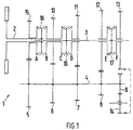
- the manual transmission 1 shown schematically in FIG. 1 has a hollow shaft trained input shaft 2, an axially parallel and partially output shaft 3 guided in the hollow shaft 2 and one axially parallel to both guided intermediate shaft 4.
- the idler gear 13 meshes via an intermediate wheel 14 which, among other things, for actuating the Serves reverse gear, with the fixed gear 9.
- Another idler gear 15 is mounted on the input shaft 2 and meshes with the fixed gear 5.
- synchronizing clutches 16 and 17 On the Output shaft 3 are two synchronizing clutches 16 and 17 rotatably mounted, of which the synchronizer clutch 16 with the idler gear 10 (Single shift C) and the idler gear 11 (single shift D) cooperates.
- the synchronizing clutch 17 acts with the idler gear 12 (Single shift E) and the idler gear 13 (single shift F) together.
- a third synchronizing clutch 18 is rotationally fixed on the input shaft 2 stored and acts on the one hand with the idler gear 15 (single shift A) and on the other hand, together with the idler gear 10 (single gear shift B).
- the synchronizing clutches 16 to 18 are non-rotatable but also axial slidably mounted on the input shaft 2 and the output shaft 3. By axial displacement of the synchronizer clutches are via the corresponding individual switching operations, the assigned idler gears non-rotatably connected to the shaft.
- To engage the first gear for example the actuation of the synchronizing clutch 18 and the Synchronizing clutch 17 required.
- the power flow through the manual transmission 1 results in a clear manner directly from the representation according to FIG. 1. On the detailed representation of the entire circuit diagrams are not discussed in detail, since this is not is essential to the invention.
- the synchronizing clutches 16 to 18 are - as already mentioned - non-rotatable. but axially displaceable, mounted on the associated shafts 2, 3.
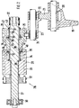
- the individual switching operations are carried out in a manner known per se axial displacement of interacting with the synchronizer clutches Shift forks 19, of which only one in FIG. 2 for the sake of clarity only is shown.
- This shift fork 19 is on a shift rod 20th attached via a shift finger 21 which in a guide groove 22 one Intermediate member 23 is guided, is axially displaceable.
- the intermediate link 23 is formed sleeve-shaped and mounted on a guide rod 24 and axially movable on this.
- the intermediate link 23 is via a guide pin 25 connected to the switching device 26.
- the switching device 26 consists essentially of a switching shaft 27 and two rotor elements 28 and 29.
- the selector shaft 27 has two bearings at the end 30, 31 in the gearbox of the gearbox, not shown stored. Through a well-known stepper, of which here only the driver part 32 connected to the shift shaft 27 in a rotationally fixed manner is shown the shift shaft is gradually rotated. Instead of twisting by one mechanical stepping mechanism can also twist the selector shaft done by electric motor.
- the first rotor element 28 is on the control shaft 27 attached. This has two circumferential on its outer circumference Guideways 33 and 34, either directly with a shift finger 21 or indirectly via an intermediate member 23, each with a shift fork 19 work together.
- Synchronizing clutch 18 is actuated while the guide track 34 with the Synchronizing clutch 16 interacts.
- the second rotor element 29 is rotatably but axially displaceably mounted on the control shaft 27. On his An outer circumferential guideway 35 is formed, in which the Guide pin 25 of the intermediate member 23 is guided. Between the first Rotor element 28 and the second rotor element 29 is a trapped Arranged spring element 36, the axial extent of which by a Ring element 37 with circumferential shoulders 38 is limited.
- the spring element 36 lies with the interposition of one of the two shoulders 38 on the first Rotor element 28 on.
- the spring element is on the opposite side 36 with the interposition of a locking ring 39 on the one hand on the shoulder 38 and on the other hand on a circumferential projection 40 of the second Rotor element. Due to the axial extension of the circumferential projection 40 on the second rotor element 29 is its axial displacement in the direction limited to the first rotor element 28 by the rotor element 29 with its inner end face 41 comes to rest on the ring member 37.
- Compensating element 42 attached, which also consists of a spring element 36, a ring element 37 with shoulders 38 and a locking ring 39.
- the spring element 36 is interposed by a shoulder 38 of the Ring element 37 on the one hand inserted into the control shaft 27 Circlip 43 on.
- the spring element is on the opposite side 36 with the interposition of the locking ring 39 on the one hand circumferential shoulder 44 of the second rotor element 29.
- the spring element 36 with the interposition of this retaining ring 39 on the Shoulder 38 of the locking ring.
- the second rotor element 29 facing shoulder 38 of the ring member 37 can be in a circumferential Immerse recess 45 of rotor element 29.
- the axial extension this recess 45 delimits the analogous to the circumferential projection 40 Displacement of the rotor element 29 after the rotor element comes to rest comes to the right ring element 37.
- the axially movable rotor element 29 By clamping the axially movable rotor element 29 is a spring-centered center position specified. By designing the spring elements as trapped springs is the central position of the axially movable rotor element 29 easily adjustable without any different spring characteristics or Spring preloads must be taken into account. By the axial Mobility of the rotor element 29 is a compensation of the different Actuation paths possible with individual switching operations taking place at the same time. Is the example of the previously described first course with the Guide track 33 interacting single shift A first completed, the individual switching process E can safely due to and for known pulling effect of the synchronizing clutch to the end become.
- the guideways should allow the individual Rotor elements are assigned that with every switching operation simultaneous actuation of two switching elements, both rotor elements or one the guideways arranged on it is effective.
Landscapes
- Engineering & Computer Science (AREA)
- General Engineering & Computer Science (AREA)
- Mechanical Engineering (AREA)
- Gear-Shifting Mechanisms (AREA)
- Structure Of Transmissions (AREA)
Claims (7)
- Dispositif de changement de vitesse pour l'actionnement d'éléments de commutation (16, 17, 18) d'une boíte de vitesses comportantcaractérisé par les autres caractéristiques suivantes:au moins deux éléments de commutation (18, 17 ou 18, 16), qui sont associés à deux arbres de transmission coaxiaux entre eux et qui peuvent coulisser axialement le long de ces arbres pour le changement de rapports de transmission, un rapport de transmission au moins étant enclenché ou supprimé par actionnement simultané des deux éléments de commutation (18, 17 ou 18, 16), et comportantun rotor de changement de vitesse (28, 29) rotatif, qui présente au moins deux voies de commutation (33 à 35), qui coopèrent avec des moyens de transmission (19 à 25) pour la conversion du mouvement de rotation du rotor de changement de vitesse en un mouvement de translation des deux déléments de changement de vitesse (18, 17 ou 18, 16),le rotor de changement de vitesse est constitué de deux éléments de rotor (28, 29) séparés, tournants et coulissant axialement l'un par rapport à l'autre, sur lesquels sont formées les deux voies de changement de vitesse ou plus, etun élément de compensation (36 à 39) est disposé entre les deux éléments de rotor (28 et 29).
- Dispositif de changement de vitesse selon la revendication 1, caractérisé en ce que les deux éléments de rotor sont disposés sur un arbre de changement de vitesse (27) commun, et en ce qu'un élément de rotor est relié fixement sur l'arbre de changement de vitesse.
- Dispositif de changement de vitesse selon la revendication 1 ou 2, caractérisé en ce que les deux éléments de rotor sont reliés solidairement en rotation entre eux, et en ce que l'élément de compensation contient un élément à ressort (36).
- Dispositif de changement de vitesse selon l'une des revendications précédentes, caractérisé en ce que l'élément de rotor (29) coulissant axialement est sollicité axialement par des éléments à ressort (36) agissant en sens opposé.
- Dispositif de changement de vitesse selon l'une des revendications précédentes, caractérisé en ce qu'au moins l'un des éléments à ressort (36) est conformé en ressort de compression, dont l'extension axiale est limitée par des moyens de limitation (32).
- Dispositif de changement de vitesse selon l'une des revendications précédentes, caractérisé en ce que le coulissement axial de l'élément de rotor (29) coulissant est limité par des butées (40, 45).
- Dispositif de changement de vitesse selon l'une des revendications précédentes, caractérisé en ce que les deux éléments de rotor (28, 29) sont en forme de douilles qui se recouvrent au moins partiellement dans leur extension axiale.
Applications Claiming Priority (3)
| Application Number | Priority Date | Filing Date | Title |
|---|---|---|---|
| DE19505323 | 1995-02-17 | ||
| DE19505323A DE19505323C1 (de) | 1995-02-17 | 1995-02-17 | Schaltvorrichtung für ein Schaltgetriebe |
| PCT/EP1995/004956 WO1996025613A1 (fr) | 1995-02-17 | 1995-12-14 | Dispositif de man×uvre pour une boite de vitesses |
Publications (2)
| Publication Number | Publication Date |
|---|---|
| EP0809766A1 EP0809766A1 (fr) | 1997-12-03 |
| EP0809766B1 true EP0809766B1 (fr) | 1999-03-10 |
Family
ID=7754198
Family Applications (1)
| Application Number | Title | Priority Date | Filing Date |
|---|---|---|---|
| EP95942161A Expired - Lifetime EP0809766B1 (fr) | 1995-02-17 | 1995-12-14 | Dispositif de manoeuvre pour une boite de vitesses |
Country Status (9)
| Country | Link |
|---|---|
| US (1) | US5921136A (fr) |
| EP (1) | EP0809766B1 (fr) |
| JP (1) | JPH11500210A (fr) |
| KR (1) | KR100370904B1 (fr) |
| CN (1) | CN1181129A (fr) |
| AU (1) | AU698035B2 (fr) |
| DE (2) | DE19505323C1 (fr) |
| ES (1) | ES2128796T3 (fr) |
| WO (1) | WO1996025613A1 (fr) |
Families Citing this family (11)
| Publication number | Priority date | Publication date | Assignee | Title |
|---|---|---|---|---|
| DE19540522C1 (de) * | 1995-10-31 | 1997-02-20 | Porsche Ag | Schaltvorrichtung für ein Schaltgetriebe zur Vermeidung des unbeabsichtigten Einlegens des Rückwärtsganges |
| DE19725512A1 (de) * | 1997-06-17 | 1998-12-24 | Zahnradfabrik Friedrichshafen | Synchronisiertes Stufengetriebe |
| DE10049245B4 (de) * | 2000-09-28 | 2010-03-25 | Schaeffler Kg | Schaltmechanismus für ein Wechselgetriebe |
| DE10253471A1 (de) * | 2002-11-16 | 2004-08-26 | Zf Friedrichshafen Ag | Schaltvorrichtung für ein Getriebe |
| DE10361356B4 (de) * | 2003-12-17 | 2006-02-16 | Getrag Getriebe- Und Zahnradfabrik Hermann Hagenmeyer Gmbh & Cie Kg | Schaltwalze mit axial zur Schaltwalzenachse beweglicher Einlegenutflanke und Schaltverfahren |
| CN100338377C (zh) * | 2004-12-31 | 2007-09-19 | 东风汽车公司 | 机械式自动变速箱拨档器执行机构 |
| DE102007040040A1 (de) | 2007-08-24 | 2009-02-26 | Zf Friedrichshafen Ag | Schaltelement umfassend zumindest drei Schaltstellungen zum Schalten von zwei Übersetzungsstufen |
| DE102009027533A1 (de) * | 2009-07-08 | 2011-01-20 | Zf Friedrichshafen Ag | Schaltvorrichtung eines Kraftfahrzeug-Schaltgetriebes |
| DE102012020426A1 (de) * | 2012-10-18 | 2014-04-24 | Volkswagen Aktiengesellschaft | Schaltvorrichtung für ein Doppelkupplungsgetriebe eines Kraftfahrzeugs bzw. Doppelkupplungsgetriebe mit einer derartigen Schaltvorrichtung |
| JP2016114199A (ja) * | 2014-12-17 | 2016-06-23 | 株式会社 神崎高級工機製作所 | ドラム型変速機構 |
| JP2016109221A (ja) * | 2014-12-08 | 2016-06-20 | 株式会社 神崎高級工機製作所 | ドラム型変速機構 |
Family Cites Families (9)
| Publication number | Priority date | Publication date | Assignee | Title |
|---|---|---|---|---|
| US1500878A (en) * | 1922-04-06 | 1924-07-08 | John F Kruchten | Power transmission |
| US2416154A (en) * | 1943-06-23 | 1947-02-18 | Wright Aeronautical Corp | Transmission |
| US2507640A (en) * | 1947-05-16 | 1950-05-16 | Macdonald James Stewart | Gear system |
| US2593416A (en) * | 1949-07-07 | 1952-04-22 | Sperry Corp | Automatic reversing mechanism |
| DE937576C (de) * | 1953-04-18 | 1956-01-12 | Duerkoppwerke Ag | Schaltvorrichtung fuer Zahnraederwechselgetriebe |
| DE1405913A1 (de) * | 1961-06-15 | 1968-12-12 | Daimler Benz Ag | Schaltvorrichtung fuer Wechselgetriebe von Fahrzeugen,insbesondere Kraftfahrzeugen |
| IT1250522B (it) * | 1991-12-11 | 1995-04-08 | Fiat Auto Spa | Dispositivo di comando per un cambio di velocita' per autoveicoli. |
| DE4205671A1 (de) * | 1992-02-25 | 1993-08-26 | Porsche Ag | Gangschaltgetriebe eines kraftfahrzeugs |
| DE4313564C1 (de) * | 1993-04-26 | 1994-06-23 | Daimler Benz Ag | Schaltvorrichtung für ein Zahnräderwechselgetriebe eines Kraftfahrzeuges |
-
1995
- 1995-02-17 DE DE19505323A patent/DE19505323C1/de not_active Expired - Fee Related
- 1995-12-14 KR KR1019970705694A patent/KR100370904B1/ko not_active Expired - Fee Related
- 1995-12-14 US US08/894,405 patent/US5921136A/en not_active Expired - Fee Related
- 1995-12-14 WO PCT/EP1995/004956 patent/WO1996025613A1/fr not_active Ceased
- 1995-12-14 DE DE59505340T patent/DE59505340D1/de not_active Expired - Fee Related
- 1995-12-14 JP JP8524598A patent/JPH11500210A/ja not_active Ceased
- 1995-12-14 ES ES95942161T patent/ES2128796T3/es not_active Expired - Lifetime
- 1995-12-14 EP EP95942161A patent/EP0809766B1/fr not_active Expired - Lifetime
- 1995-12-14 AU AU43451/96A patent/AU698035B2/en not_active Ceased
- 1995-12-14 CN CN95197814A patent/CN1181129A/zh active Pending
Also Published As
| Publication number | Publication date |
|---|---|
| CN1181129A (zh) | 1998-05-06 |
| JPH11500210A (ja) | 1999-01-06 |
| EP0809766A1 (fr) | 1997-12-03 |
| AU698035B2 (en) | 1998-10-22 |
| ES2128796T3 (es) | 1999-05-16 |
| KR19980702297A (ko) | 1998-07-15 |
| US5921136A (en) | 1999-07-13 |
| AU4345196A (en) | 1996-09-04 |
| KR100370904B1 (ko) | 2003-03-26 |
| DE19505323C1 (de) | 1996-04-04 |
| WO1996025613A1 (fr) | 1996-08-22 |
| DE59505340D1 (de) | 1999-04-15 |
Similar Documents
| Publication | Publication Date | Title |
|---|---|---|
| DE69022767T2 (de) | Schaltmechanismus mit einer einzigen Schaltstange. | |
| DE19610104C2 (de) | Schaltvorrichtung für ein Zahnräderwechselgetriebe sowie Verfahren zum Steuern dafür | |
| EP0128319B1 (fr) | Boîte à vitesses avec marche arrière synchronisée | |
| EP1616116B1 (fr) | Boite de vitesses multi-etagee pour moteur a combustion interne | |
| DE2633730A1 (de) | Kraftuebertragung aus einem hauptschaltgetriebe in reihe mit einem zusatzgetriebe fuer wenigstens zwei stufen | |
| EP0809766B1 (fr) | Dispositif de manoeuvre pour une boite de vitesses | |
| DE19635866C2 (de) | Schaltvorrichtung für ein Zahnräderwechselgetriebe | |
| DE2935590C2 (de) | Schaltvorrichtung für ein Fünfganggetriebe | |
| DE1904663A1 (de) | Handgeschaltetes Getriebe fuer Kraftfahrzeuge mit zwei Antriebsbereichen | |
| DE2653035C3 (de) | Schaltvorrichtung für ein Kraftfahrzeugwechselgetriebe | |
| DE4109942A1 (de) | Schaltgestaenge mit ein manuell schaltbares getriebe | |
| EP1841990A1 (fr) | Actionneur de transmission de vehicule destine a actionner une transmission de vehicule | |
| DE3520274A1 (de) | Vorrichtung zum waehlen einer leistungsuebertragungsanordnung eines vierradgetriebenen kraftfahrzeugs | |
| WO2012062536A1 (fr) | Transmission à groupes pour des véhicules automobiles | |
| EP0771975A1 (fr) | Changement de vitesse pour boîte de vitesses | |
| EP0727599B1 (fr) | Dispositif de changement de vitesse pour transmission | |
| EP1711727B1 (fr) | Systeme de changement de vitesses | |
| DE3842818C1 (en) | Selector device for a motor-vehicle gearbox | |
| DE102018206392A1 (de) | Schalteinrichtung zur durchführung von gangwechseln in einem fahrzeuggetriebe | |
| DE3333423A1 (de) | Mechanische schalteinrichtung | |
| DE4332440A1 (de) | Gangwahlvorrichtung für ein Handschaltgetriebe | |
| DE102013223870A1 (de) | Vorrichtung und Verfahren zum Wählen und Schalten | |
| DE19737305C1 (de) | Schaltvorrichtung für ein Zahnräderwechselgetriebe | |
| DE4441967A1 (de) | Schaltvorrichtung für mehrgängiges Wechselgetriebe | |
| DE675985C (de) | Zahnraederwechselgetriebe, insbesondere fuer Kraftfahrzeuge |
Legal Events
| Date | Code | Title | Description |
|---|---|---|---|
| PUAI | Public reference made under article 153(3) epc to a published international application that has entered the european phase |
Free format text: ORIGINAL CODE: 0009012 |
|
| 17P | Request for examination filed |
Effective date: 19970813 |
|
| AK | Designated contracting states |
Kind code of ref document: A1 Designated state(s): DE ES FR GB IT SE |
|
| GRAG | Despatch of communication of intention to grant |
Free format text: ORIGINAL CODE: EPIDOS AGRA |
|
| GRAG | Despatch of communication of intention to grant |
Free format text: ORIGINAL CODE: EPIDOS AGRA |
|
| GRAH | Despatch of communication of intention to grant a patent |
Free format text: ORIGINAL CODE: EPIDOS IGRA |
|
| 17Q | First examination report despatched |
Effective date: 19980715 |
|
| ITF | It: translation for a ep patent filed | ||
| GRAH | Despatch of communication of intention to grant a patent |
Free format text: ORIGINAL CODE: EPIDOS IGRA |
|
| GRAA | (expected) grant |
Free format text: ORIGINAL CODE: 0009210 |
|
| AK | Designated contracting states |
Kind code of ref document: B1 Designated state(s): DE ES FR GB IT SE |
|
| GBT | Gb: translation of ep patent filed (gb section 77(6)(a)/1977) |
Effective date: 19990315 |
|
| REF | Corresponds to: |
Ref document number: 59505340 Country of ref document: DE Date of ref document: 19990415 |
|
| ET | Fr: translation filed | ||
| REG | Reference to a national code |
Ref country code: ES Ref legal event code: FG2A Ref document number: 2128796 Country of ref document: ES Kind code of ref document: T3 |
|
| PGFP | Annual fee paid to national office [announced via postgrant information from national office to epo] |
Ref country code: SE Payment date: 19991213 Year of fee payment: 5 |
|
| PGFP | Annual fee paid to national office [announced via postgrant information from national office to epo] |
Ref country code: ES Payment date: 19991228 Year of fee payment: 5 |
|
| PLBE | No opposition filed within time limit |
Free format text: ORIGINAL CODE: 0009261 |
|
| STAA | Information on the status of an ep patent application or granted ep patent |
Free format text: STATUS: NO OPPOSITION FILED WITHIN TIME LIMIT |
|
| 26N | No opposition filed | ||
| PGFP | Annual fee paid to national office [announced via postgrant information from national office to epo] |
Ref country code: GB Payment date: 20001213 Year of fee payment: 6 |
|
| PG25 | Lapsed in a contracting state [announced via postgrant information from national office to epo] |
Ref country code: SE Free format text: LAPSE BECAUSE OF NON-PAYMENT OF DUE FEES Effective date: 20001215 |
|
| EUG | Se: european patent has lapsed |
Ref document number: 95942161.1 |
|
| PG25 | Lapsed in a contracting state [announced via postgrant information from national office to epo] |
Ref country code: GB Free format text: LAPSE BECAUSE OF NON-PAYMENT OF DUE FEES Effective date: 20011214 |
|
| PG25 | Lapsed in a contracting state [announced via postgrant information from national office to epo] |
Ref country code: ES Free format text: LAPSE BECAUSE OF NON-PAYMENT OF DUE FEES Effective date: 20011215 |
|
| REG | Reference to a national code |
Ref country code: GB Ref legal event code: IF02 |
|
| GBPC | Gb: european patent ceased through non-payment of renewal fee |
Effective date: 20011214 |
|
| PGFP | Annual fee paid to national office [announced via postgrant information from national office to epo] |
Ref country code: FR Payment date: 20021230 Year of fee payment: 8 |
|
| PGFP | Annual fee paid to national office [announced via postgrant information from national office to epo] |
Ref country code: DE Payment date: 20030213 Year of fee payment: 8 |
|
| REG | Reference to a national code |
Ref country code: ES Ref legal event code: FD2A Effective date: 20020112 |
|
| PG25 | Lapsed in a contracting state [announced via postgrant information from national office to epo] |
Ref country code: DE Free format text: LAPSE BECAUSE OF NON-PAYMENT OF DUE FEES Effective date: 20040701 |
|
| PG25 | Lapsed in a contracting state [announced via postgrant information from national office to epo] |
Ref country code: FR Free format text: LAPSE BECAUSE OF NON-PAYMENT OF DUE FEES Effective date: 20040831 |
|
| REG | Reference to a national code |
Ref country code: FR Ref legal event code: ST |
|
| PG25 | Lapsed in a contracting state [announced via postgrant information from national office to epo] |
Ref country code: IT Free format text: LAPSE BECAUSE OF NON-PAYMENT OF DUE FEES Effective date: 20051214 |