EP0809400B1 - Appareil de production de signaux vidéo à compatibilité descendante et avec une résolution verticale augmentée - Google Patents
Appareil de production de signaux vidéo à compatibilité descendante et avec une résolution verticale augmentée Download PDFInfo
- Publication number
- EP0809400B1 EP0809400B1 EP19970113843 EP97113843A EP0809400B1 EP 0809400 B1 EP0809400 B1 EP 0809400B1 EP 19970113843 EP19970113843 EP 19970113843 EP 97113843 A EP97113843 A EP 97113843A EP 0809400 B1 EP0809400 B1 EP 0809400B1
- Authority
- EP
- European Patent Office
- Prior art keywords
- video signal
- interlaced
- definition
- frame
- progressive
- Prior art date
- Legal status (The legal status is an assumption and is not a legal conclusion. Google has not performed a legal analysis and makes no representation as to the accuracy of the status listed.)
- Expired - Lifetime
Links
Images


Classifications
-
- H—ELECTRICITY
- H04—ELECTRIC COMMUNICATION TECHNIQUE
- H04N—PICTORIAL COMMUNICATION, e.g. TELEVISION
- H04N7/00—Television systems
- H04N7/01—Conversion of standards, e.g. involving analogue television standards or digital television standards processed at pixel level
- H04N7/0125—Conversion of standards, e.g. involving analogue television standards or digital television standards processed at pixel level one of the standards being a high definition standard
-
- G—PHYSICS
- G11—INFORMATION STORAGE
- G11B—INFORMATION STORAGE BASED ON RELATIVE MOVEMENT BETWEEN RECORD CARRIER AND TRANSDUCER
- G11B27/00—Editing; Indexing; Addressing; Timing or synchronising; Monitoring; Measuring tape travel
- G11B27/02—Editing, e.g. varying the order of information signals recorded on, or reproduced from, record carriers
- G11B27/031—Electronic editing of digitised analogue information signals, e.g. audio or video signals
- G11B27/032—Electronic editing of digitised analogue information signals, e.g. audio or video signals on tapes
-
- H—ELECTRICITY
- H04—ELECTRIC COMMUNICATION TECHNIQUE
- H04N—PICTORIAL COMMUNICATION, e.g. TELEVISION
- H04N19/00—Methods or arrangements for coding, decoding, compressing or decompressing digital video signals
- H04N19/40—Methods or arrangements for coding, decoding, compressing or decompressing digital video signals using video transcoding, i.e. partial or full decoding of a coded input stream followed by re-encoding of the decoded output stream
-
- H—ELECTRICITY
- H04—ELECTRIC COMMUNICATION TECHNIQUE
- H04N—PICTORIAL COMMUNICATION, e.g. TELEVISION
- H04N19/00—Methods or arrangements for coding, decoding, compressing or decompressing digital video signals
- H04N19/85—Methods or arrangements for coding, decoding, compressing or decompressing digital video signals using pre-processing or post-processing specially adapted for video compression
-
- H—ELECTRICITY
- H04—ELECTRIC COMMUNICATION TECHNIQUE
- H04N—PICTORIAL COMMUNICATION, e.g. TELEVISION
- H04N5/00—Details of television systems
- H04N5/76—Television signal recording
- H04N5/91—Television signal processing therefor
- H04N5/92—Transformation of the television signal for recording, e.g. modulation, frequency changing; Inverse transformation for playback
- H04N5/9201—Transformation of the television signal for recording, e.g. modulation, frequency changing; Inverse transformation for playback involving the multiplexing of an additional signal and the video signal
- H04N5/9206—Transformation of the television signal for recording, e.g. modulation, frequency changing; Inverse transformation for playback involving the multiplexing of an additional signal and the video signal the additional signal being a character code signal
-
- H—ELECTRICITY
- H04—ELECTRIC COMMUNICATION TECHNIQUE
- H04N—PICTORIAL COMMUNICATION, e.g. TELEVISION
- H04N7/00—Television systems
- H04N7/01—Conversion of standards, e.g. involving analogue television standards or digital television standards processed at pixel level
- H04N7/0112—Conversion of standards, e.g. involving analogue television standards or digital television standards processed at pixel level one of the standards corresponding to a cinematograph film standard
-
- H—ELECTRICITY
- H04—ELECTRIC COMMUNICATION TECHNIQUE
- H04N—PICTORIAL COMMUNICATION, e.g. TELEVISION
- H04N7/00—Television systems
- H04N7/01—Conversion of standards, e.g. involving analogue television standards or digital television standards processed at pixel level
- H04N7/0117—Conversion of standards, e.g. involving analogue television standards or digital television standards processed at pixel level involving conversion of the spatial resolution of the incoming video signal
- H04N7/012—Conversion between an interlaced and a progressive signal
-
- G—PHYSICS
- G11—INFORMATION STORAGE
- G11B—INFORMATION STORAGE BASED ON RELATIVE MOVEMENT BETWEEN RECORD CARRIER AND TRANSDUCER
- G11B2220/00—Record carriers by type
- G11B2220/20—Disc-shaped record carriers
-
- G—PHYSICS
- G11—INFORMATION STORAGE
- G11B—INFORMATION STORAGE BASED ON RELATIVE MOVEMENT BETWEEN RECORD CARRIER AND TRANSDUCER
- G11B2220/00—Record carriers by type
- G11B2220/90—Tape-like record carriers
-
- H—ELECTRICITY
- H04—ELECTRIC COMMUNICATION TECHNIQUE
- H04N—PICTORIAL COMMUNICATION, e.g. TELEVISION
- H04N5/00—Details of television systems
- H04N5/76—Television signal recording
- H04N5/765—Interface circuits between an apparatus for recording and another apparatus
- H04N5/775—Interface circuits between an apparatus for recording and another apparatus between a recording apparatus and a television receiver
-
- H—ELECTRICITY
- H04—ELECTRIC COMMUNICATION TECHNIQUE
- H04N—PICTORIAL COMMUNICATION, e.g. TELEVISION
- H04N5/00—Details of television systems
- H04N5/76—Television signal recording
- H04N5/91—Television signal processing therefor
Definitions
- the present invention relates to an apparatus for deriving, from a motion picture fixed in a motion picture film, the motion picture including plural frames, an increased-definition interlaced video signal representing the motion picture for recording on a non-volatile recording medium a standard-definition video signal based on the increased-definition interlaced video signal and having an increased vertical resolution.
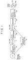
- FIG. 1 is a block diagram of a telecine system for transferring a motion picture film to a consumer recording medium, such as a video cassette or a video disk.
- the high-definition (HD) telecine apparatus 61 is provided internally with a high-definition image sensor, not shown, on which an image of each frame of the motion picture film is formed, and which is generates an interlaced high-definition video signal in which each frame has 1125 horizontal scanning lines, has an aspect ratio of 16:9.
- horizontal scanning lines will from now on be called "lines”.
- the interlaced high-definition video signal has an interlace ratio of 2:1, i.e., each frame of the video signal consists of two overlapping fields, offset from one another by one line.
- an interlaced video signal will be understood to refer to an interlaced video signal with an interlace ratio of 2:1.
- the motion picture film 1 reproduced for example by the HD telecine apparatus 61
- it is transported at a rate that provides a frame rate of 24 Hz.
- the image sensor in the HD telecine apparatus 61 produces an interlaced high-definition video signal with a field rate of 60 Hz. Therefore, ten fields, i.e., five frames, of the interlaced high-definition video signal must be derived from each four frames of the motion picture film.
- the HD telecine apparatus 61 performs 2-3 pulldown to derive an interlaced high-definition video signal with a field rate of 60 Hz from the motion picture film 1.
- ten fields, i.e., five frames, of the high-definition video signal are derived from four frames of the motion picture film 1.
- a different number of fields of the high-definition video signal is derived from alternate frames of the motion picture film.
- Two fields of the interlaced high-definition video signal i.e., the first and second fields of the high-definition video signal, are derived from the first frame of the motion picture film 1.
- three fields of the interlaced high-definition video signal i.e., the third, fourth and fifth fields of the high-definition video signal are derived from the second frame of the motion picture film 1. This process is then repeated.
- the interlaced high-definition video signal from the telecine apparatus 61 is fed into the high-definition video recorder (HD-VTR) 3 where it is recorded on a recording medium, not shown, such as a video tape.
- a recording medium not shown, such as a video tape.
- the interlaced high-definition video signal is reproduced by the HD-VTR 3, and is fed to the down-converter 62.
- the down-converter 62 comprises the field memories 81 and 82, and the filter 83.
- the down-converter 62 reduces the number of lines and the number of pixels to convert the input interlaced high-definition video signal into a video signal of the type used in normal television broadcasting, with 525 lines, an aspect ratio of 4:3, and an interlace ratio 2:1. Such a signal will from now on be referred to as "an interlaced standard-definition video signal.”
- the field memory 81 of the down-converter 62 temporarily stores each frame of the input interlaced high-definition video signal.
- the interlaced high-definition video signal is read from the field memory 81 in timed read cycles and fed to the filter 83.
- the filter 83 which is, for example, a 3 ⁇ 3 two-dimensional filter, thins out the lines and pixels of the interlaced high-definition video signal by filtering to convert the input interlaced high-definition video signal into an interlaced standard-definition video signal.
- Each frame of the interlaced standard-definition video signal provided by the filter 83 is stored temporarily in the field memory 82.
- the fields of the interlaced standard-definition video signals are sequentially read out of the field memory 82 in the down converter 4 and are fed to the standard-definition video recorder (SD-VTR) 5, shown in Figure 1, which records them on a recording medium, not shown, such as a video tape.
- SD-VTR standard-definition video recorder
- the motion picture film 1 is converted into an interlaced standard-definition video signal that can be reproduced on a regular, standard-definition television set, and the interlaced standard-definition video signal is recorded by the SD-VTR 5.
- the interlaced standard-definition video signal is reproduced by the SD-VTR 5, and is fed into the encoder 70.
- the encoder 70 converts the interlaced standard-definition video signal into a composite video signal, such as an NTSC-format composite video signal, or a PAL-format composite video signal, which is fed to the duplicating apparatus 63.
- the duplicating apparatus 63 records the composite video signal on the consumer-format video cassette 72 or the video disk 82.
- the motion picture film 1 is converted into an interlaced standard-definition video signal with 525 lines, an aspect ratio 4:3, and an interlace ratio of 2:1 by the standard-definition (SD) telecine apparatus 9.
- the SD telecine apparatus 9 includes in internal image sensor, not shown, which converts the motion picture film into an interlaced standard-definition video signal using 2-3 pulldown, and records the resulting interlaced standard-definition video signal on the SD-VTR 5.
- the interlaced standard-definition video signal recorded on, for example, the video disk 8 is reproduced by the video disk player 71 capable of reproducing video disks whereon an interlaced standard-definition video signal is recorded.
- Pictures represented by the reproduced interlaced standard-definition video signal are displayed on the display 55.
- the motion picture film 1 is converted by the HD telecine apparatus 61 or the SD telecine apparatus 9 into an interlaced standard-definition video signal.
- the arrangement shown may not provide an optimum vertical resolution.
- the effective vertical resolution of the image is Kc times the number of effective lines.
- Kc is normally called the Kell factor, but is called the camera factor in the paper, and is less than unity.
- the effective vertical resolution of a picture displayed by interlaced scanning is ⁇ times the number of lines.
- the factor ⁇ is called the interlace factor in the paper, and, again, is less than unity. Consequently, the vertical resolution of the picture displayed on the display 55 ( Figure 3) is Kc ⁇ ⁇ times the number of lines.
- both Kc and ⁇ are in the range of about 0.6 to about 0.8, so the vertical resolution of the picture displayed on the display 55 ( Figure 3) is in the range of about 0.4 to 0.6 times the number of lines.
- interline flicker When an interlaced standard-definition video signal is derived from an image having points spanning more than one line using a large camera factor Kc, points in the image that appear in, for example, the odd field disappear when the even field is displayed. This causes the points to appear to move between alternate fields, which results in an annoying flicker called interline flicker.
- a camera factor Kc in the range of about 0.6 to about 0.8 is preferable. This causes the point to appear in both fields, but reduces the vertical resolution.
- EDTV extended-definition television
- EDTV is intended to display a high resolution picture, without exhibiting visible flicker.
- EDTV is also intended to maintain downward compatibility with interlaced standard-definition video signals, i.e., NTSC video signals in the United States and Japan.
- interlaced standard-definition video signals i.e., NTSC video signals in the United States and Japan.
- NTSC interlaced standard-definition video signals
- a system for providing a progressive-scan video display signals from a received video signal derived from a film having successive image frames by producing odd and even video fields from each film frame, with the video fields being produced at a greater rate than the film frame rate and in a repetitive sequentially varying relationship to the film frames is known from US-A-4 881 125. Further, there is known from WO-A-92 09172 a video system in which a processed or transmitted video signal can be derived from a camera source or from a film source. The video signal has a data location which indicates whether the signal is originally greened from an optical image by a camera source or a Teledyne.
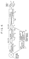
- FIG. 4 is a block diagram of a telecine system employing an image processing apparatus embodying the present invention.
- the high-definition (HD) telecine apparatus 2 is provided internally with a high-definition image sensor, not shown, on which an image of each frame of the motion picture film is formed, and which generates a high-definition video signal representing each frame of the motion picture film.
- the HD telecine apparatus 2 scans the image of each frame of the motion picture film 1 to generate from each frame of the motion picture film a frame of an interlaced high-definition video signal with 1125 lines and an aspect ratio of 16:9.
- the interlaced high-definition video signal has an interlace ratio of 2:1, i.e., each frame of the video signal is represented by two overlapping fields offset from one another by one line.
- interlaced video signal has an interlace ratio of 2:1.
- the HD telecine apparatus 2 derives each frame of an interlaced high-definition video signal from one frame of the motion picture film 1 using 2-2 pulldown, in which two fields (one frame) of the interlaced high-definition video signal are derived from each frame of the motion picture film 1.
- the high-definition video recorder (HD-VTR) 3 temporarily records the 48 fields per second (48-field) interlaced high-definition video signal from the HD telecine apparatus 2 on a recording medium, not shown, such as a video tape.
- the HD-VTR 3 reproduces the interlaced high-definition video signal from the recording medium, and feeds the resulting reproduced high-definition video signal VI1 to the down-converter 4.
- Figure 5A shows the down-converter 4, which is an embodiment of the image converting apparatus according to the present invention.
- the down converter 4 converts the 48-field interlaced high-definition signal VI1 from the HD-VTR 3 into a 24 frames per second (24-frame) progressive (non-interlaced) high-definition signal VI2 before the down conversion process. After down conversion, the down converter 4 converts the 24-frame progressive standard definition video signal VO1 to the interlaced standard-definition signal VO2.
- the down-converter 4 includes the memory unit 21 which converts the 48-field interlaced high-definition video signal VI1 from the HD-VTR 3 into the 24-frame progressive high-definition video signal VI2.
- the down-converter 4 also includes the filter 24 which filters the 24-frame progressive high-definition video signal VI2 to convert the 24-frame progressive high-definition video signal VI1 into the 24-frame progressive standard-definition video signal VO1.
- the down-converter 4 includes the memory unit 25, which converts the 24-frame progressive standard-definition video signal VO1 into the interlaced standard-definition signal VO2.
- the memory unit 21 includes the memory banks 22a and 22b, and the switches 23a and 23b.
- the switch 23a switches between the inputs of the memory banks 22a and 22b at the same rate as, and in synchronism with, the field rate of the 48-field high-definition video signal VI1. This connects the fields of the video signal VI1 alternately to the memory banks 22a and 22b. Consequently, alternate fields of the video signal VI1 are stored in the memory banks 22a and 22b.
- the memory bank 22a temporarily stores the odd fields of the video signal VI1
- the memory bank 22b temporarily stores the even fields of the video signal VI1.
- the switch 23b switches between the outputs of the memory banks 22a and 22b at the same rate as, and in synchronism with, the line rate of the 24-frame progressive high-definition video signal VI2 fed to the filter 24. This connects the memory banks 22a and 22b alternately to the filter 24, so that the odd lines of the 24-frame progressive high-definition video signal VI2 originate in the memory bank 22a, and the even lines of the 24-frame progressive high-definition video signal VI2 originate in the memory bank 22b.
- the memory unit 21 converts each frame (two fields) of the 48-field interlaced high-definition video signal VI1 from the HD-VTR 3 into a frame of the 24-frame progressive high-definition video signal VI2, which it feeds to the filter 24.
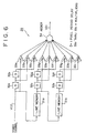
- the filter 24 is, for example, a two-dimensional 3 ⁇ 3 filter having the configuration shown in Figure 6.
- the 24-frame progressive high-definition video signal VI2 is fed from the memory unit 21 into the delay circuit (D) 32a, the multiplier 33a and the line memory 31a.
- the delay circuit 32a delays the video signal VI2 by one pixel period, which is the time corresponding to one pixel of the high-definition video signal, and feeds the resulting delayed video signal to the delay circuit 32b and the multiplier 33b.
- the delay circuit 32b delays the delayed video signal from the delay circuit 32a by one pixel period, and feeds the additionally-delayed video signal to the multiplier 33c.
- the multipliers 33a through 33c multiply the video signal VI2, the video signal from the delay circuit 32a, and the video signal from the delay circuit 32b by the weighting factors a 11 , a 12 and a 13 , respectively.
- the respective output signals of the multipliers 33a through 33c are fed into the summing circuit 34.
- the line memory 31a delays the high-definition video signal VI2 from the memory unit 21 by one line period, which is the time corresponding to one line of the high-definition video signal VI2, and feeds the one-line delayed video signal to the delay circuit 32c, the multiplier 33d, and the line memory 31b.
- the delay circuit 32c delays the one-line delayed video signal from the line memory 31a by one pixel period, and feeds the resulting delayed video signal to the delay circuit 32d, and the multiplier 33e.
- the delay circuit 32d delays the video signal from the delay circuit 32c by an additional one pixel period, and feeds the additionally-delayed video signal to the multiplier 33f.
- the multipliers 33d through 33f multiply the one-line delayed video signal from the line memory 31a, the video signal from the delay circuit 32c, and the video signal from the delay circuit 32d by the weighting factors a 21 , a 22 , and a 23 , respectively.
- the output signals from the multipliers 33d through 33f are fed to the summing circuit 34.
- the line memory 31b delays the high-definition video signal from the line memory 31a by an additional line period, and feeds the two-line period delayed video signal to the delay circuit 32e and the multiplier 33g.
- the delay circuit 32e delays the two-line delayed high-definition video signal from the line memory 31b by one pixel period, and feeds the resulting delayed video signal to the delay circuit 32f and the multiplier 33h.
- the delay circuit 32f delays the video signal from the delay circuit 32e by an additional one pixel period, and feeds the additionally-delayed video signal to the multiplier 33i.
- the multipliers 33g through 33i multiply the two-line delayed video signal from the line memory 31b, the video signal from the delay circuit 32e, and the video signal from the delay circuit 32f by the weighting factors a 31 , a 32 , and a 33 , respectively.
- the output signals from the multipliers 33g through 33i are fed into the summing circuit 34.
- the summing circuit 34 generates the output signal VO1 by adding together the outputs of the multipliers 33a through 33i.
- the filter 24 thins out the lines and the pixels of each frame of the 24-frame progressive high-definition video signal VI2 received from the memory unit 21. In this way, the 24-frame progressive high-definition video signal VI2 is converted into a 24-frame progressive standard-definition video signal VO1 having 525 lines and an aspect ratio of 4:3.
- the 24-frame progressive standard-definition video signal VO1 may be fed directly to the duplicating apparatus 6 for copying onto the consumer recording medium.
- the 24-frame progressive standard-definition video signal is fed from the filter 24 to the memory unit 25 ( Figure 5A).
- the memory unit 25 comprises the memory banks 26a and 26b, and the switches 27a and 27b.
- the switch 27a is synchronized to the line rate of the 24-frame progressive standard-definition video signal and connects the output of the filter 24 alternately to the memory banks 26a and 26b during each line of the signal.
- odd lines (even lines) of the progressive standard-definition video signal are fed to the memory bank 26a, and even lines of the progressive standard-definition video signal are fed to the memory bank 26b.
- the memory bank 26a sequentially stores the odd lines of the 24-frame progressive standard-definition video signal received from the filter 24 via the switch 27a.
- the memory bank 26b sequentially stores the even lines of the 24-frame progressive standard-definition video signal received from the filter 24 via the switch 27a. Consequently, odd fields consisting of odd lines and even fields consisting of even lines of a 48-field interlaced standard-definition video signal are stored in the memory bank 26a and the memory bank 26b, respectively.
- the switch 27b may be caused to operate at the field rate of a 48-field interlaced standard definition video signal to connect the memory banks 26a and 26b alternately to the standard definition video recorder (SD-VTR) 5.
- SD-VTR standard definition video recorder
- the switch 27b operates at the field rate of a 60 field per second (60-field) interlaced standard definition video signal to connect the memory banks 26a and 26b alternately to the standard definition video recorder (SD-VTR) 5.
- the switch 27b performs 3-2 pull-down to convert the fields of a 48-field interlaced standard-definition video signal stored in the memory banks 26a and 26 to the 60-field interlaced standard-definition video signal VO2.
- the switch 27b feeds the odd fields stored in the memory bank 26a and the even fields stored in the memory bank 26b in the alternating sequence to be described next to the SD-VTR 5.
- the switch 27b performs 3:2 pull down as follows.
- the switch 27b first feeds a first field (an odd field) from the memory bank 26a, the second field (an even field) from the memory bank 26b, the third field (an odd field) from the memory bank 26a and the fourth field (an even field) from the memory bank 26b to the SD-VTR 5.
- the switch 27b then returns to the memory bank 26a, which still contains the third field.
- the switch 27b then feeds the third field (an odd field) from the memory bank 26a to the SD-VTR 5 for a second time.
- the switch 27b then switches to the memory bank 26b, and feeds the sixth field (an even field) to the SD-VTR 5.
- the switch 26b returns to the memory bank 26a, the contents of which have now changed to the fifth field, and feeds the fifth field (an odd field) to the SD-VTR 5.
- the switch 27b then feeds the eighth field (an even field) from the memory bank 26b, and the seventh field from the memory bank 26a to the SD-VTR 5.
- the switch 27b After feeding the seventh field from the memory bank 26a, the switch 27b returns to the memory bank 26b, which still contains the eighth field.
- the switch 27b then feeds the eighth field from the memory bank 26b to the SD-VTR 5 for a second time.
- the switch 27b then returns to the memory bank 26a and the sequence then repeats.
- ten fields of the 60-field interlaced standard-definition video signal VO2 are derived from every eight fields of the 48-field interlaced standard-definition video signal stored in the memory banks 26a and 26b.
- FIG. 5A The state of the video signal as it passes through the down converter 4 (Figure 5A) is illustrated in Figure 5B.
- the switches 23a and 23b and the switches 27a and 27b are realized using memory controllers controlling the write addresses and the read addresses of the respective memory banks 22a and 22b, and 26a and 26b.
- the memory unit 25 converts the 24-frame progressive standard-definition video signal into the 60-field interlaced standard-definition video signal VO2, and feeds the 60-field interlaced standard-definition video signal to the SD-VTR 5.
- the SD-VTR 5 ( Figure 4) records the 60-field interlaced standard-definition video signal VO2 from the down-converter 4 on a recording medium, such as a video tape.
- the vertical resolution of the 48-field interlaced high-definition video signal provided by the telecine apparatus 2 is reduced by the product of the number of lines, i.e., 1125, and the camera factor Kc.
- the camera factor Kc 0.6, i.e., the smallest value in the above-mentioned range of the camera factor, the vertical resolution is still greater than the number of effective lines in a 60-field interlaced standard-definition video signal, which is usually about 480 lines in the NTSC system.
- the down-convener 4 converts the 48-field interlaced high-definition video signal VI1 having a high vertical resolution into the 24-frame progressive high-definition video signal VI2, and converts the 24-frame progressive high-definition video signal VI2 into the 24-frame interlaced standard-definition video signal VO1
- the vertical resolution of the 60-field interlaced standard-definition video signal VO2 from the down-converter 4 is substantially equal to the number of effective lines in the 60-field interlaced standard-definition video signal VO2.
- the signal provided by the down converter 4 will therefore be referred to as the increased vertical resolution (IVR) 60-field interlaced standard-definition video signal VO2.
- the IVR 60-field interlaced standard-definition video signal VO2 can be recorded by the SD-VTR 5, a conventional VTR.
- the IVR 60-field interlaced standard-definition video signal VO2 recorded by the SD-VTR 5 is reproduced by the SD-VTR 5, and fed to the encoder 70.
- the encoder 70 converts the IVR 60-field interlaced standard-definition video signal VO2 reproduced by the SD-VTR 5 into an IVR composite video signal, such as an IVR NTSC composite video signal or an IVR PAL composite video signal, and feeds the resulting IVR composite video signal to the duplicating apparatus 6.
- the duplicating apparatus 6 makes copies of the IVR composite video signal on a consumer recording medium, such as the video cassette 7 or the video disk 8. Alternatively, the duplicating apparatus 6 can make copies of the IVR composite video signal on industrial or professional recording media.
- the duplicating system 6 can be a distribution system, such as a broadcast, cable, telephone, or ISDN distribution system, through which the signal from the SD-VTR 5 is distributed to the end user.
- a distribution system such as a broadcast, cable, telephone, or ISDN distribution system
- consumer recording medium will be understood also to include industrial and professional recording media, and such distribution media as broadcast, cable, telephone, or ISDN.
- the IVR composite video signal recorded on the consumer video medium such as the video cassette 7 or the video disk 8 is an interlaced video signal and has a high vertical resolution
- interline flicker occurs when the IVR composite video signal is displayed in the interlaced scanning mode of a standard TV broadcasting system. Consequently, the resulting pictures are perceived as having a poor picture quality.
- the duplicating apparatus 6 is adapted to record scanning mode information on the end-user format medium in addition to the IVR composite video signal.
- the scanning mode information indicates that an IVR composite video signal is recorded on the consumer recording medium, and that the IVR composite video signal should be displayed using progressive scanning.
- the scanning mode information can be recorded in the Table of Contents (TOC) of the consumer recording medium, such as the video cassette 7 or the video disk 8.
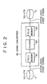
- FIG 8 is a block diagram of a reproducing and displaying system embodying the present invention for reproducing and displaying the IVR composite video signal recorded on, for example, the video disk 8 by the duplicating apparatus 6 shown in Figure 4.
- the IVR composite video signal is an 60-field interlaced standard-definition video signal with increased vertical resolution.
- the reproducing and displaying system comprises the disk reproducer 40 and the display unit 50.
- the disk reproducer 40 comprises the disk playback system 41, the video/audio decoder 42, the control circuit 43, and the user interface 44.
- the disk reproducer 40 reproduces the information recorded on the disk 8 by the duplicating apparatus 6 shown in Figure 4.
- the disk reproducer 40 is also capable of reproducing a conventionally-recorded disk, such as disk 72 recorded by the conventional duplicating apparatus 63 shown in Figure 1.
- the control circuit 43 When the disk reproducer 40 reproduces the information recorded on the disk 8, the control circuit 43 first causes the disk playback system 41 to read the Table of Contents (TOC) information recorded on the disk 8.
- the disk playback system 41 reproduces the information recorded on the disk 8, and feeds an RF signal to the video/audio decoder 42.
- the control circuit 43 causes the video/audio decoder 42 to decode the RF signal to provide a video signal and audio signal.
- the video signal produced by the video/audio decoder 42 appears at the video terminal 45a, and the audio signal is fed to the audio output terminal 45c for connecting to a suitable amplifier and loudspeaker (not shown).
- the control circuit 43 detects the scanning mode information included in the TOC information reproduced from the disk 8. When the control circuit 43 finds scanning mode information in the TOC information, indicating that the composite video signal recorded on the disk 8 is to be displayed using progressive scanning, the control circuit feeds a set scanning mode 0 signal to the scanning mode output terminal 45b to set the scanning mode of the display unit 50 to progressive scanning.
- control circuit 43 finds no scanning mode information in the TOC information, it determines that the video signal recorded on the disk 8 is to be displayed using interlaced scanning, and feeds a set scanning mode 1 signal to the scanning mode output terminal 45b to set the scanning mode of the display unit 50 to interlaced scanning.
- the user interface 44 includes a control panel, not shown, provided with, for example, a main switch, a playback button, a fast forward button, a rewind button, and the like.
- the user interface also includes indicators for showing the operational state of the disk reproducer 40, such as playback, fast forward, rewind, and the like.
- the user interface also displays the playing time of the information reproduced from the disk 8.
- the control circuit 43 controls the operation of the disk reproducer 40 in response to command signals entered by user operating the control panel.
- the control circuit 43 also provides information about the operational state of the disk reproducer 40, the playing time of the information recorded on the disk 8, which is known from the TOC information, and the like, to the user interface 44, for display to the user.
- the display unit 50 comprises the sync separator circuit 52, the scanning mode converting circuit 53, the video signal processing circuit 54, the display 55, for example, a CRT, and the scanning circuit 56.
- the display unit 50 also includes the video input terminal 51a, and the scanning mode input terminal 51b for connection to the video output terminal 45a and the scanning mode output terminal 45b, respectively, of the disk reproducer 40.
- the sync separator circuit 52 separates the synchronizing signals from the video signal fed from the disk reproducer 40 via the video output terminal 45a and the video terminal 51a.
- the sync separator circuit feeds the synchronizing signals to the scanning circuit 56, and feeds the remainder of the video signal to the scanning mode converting circuit 53.
- the scanning mode converting circuit 53 sets the scanning mode of the video signal from the sync separator circuit 52 in response to the scanning mode setting signal received from the disk reproducer 40 via the scanning mode output terminal 45b and the scanning mode input terminal 51b.
- the scanning mode converting circuit 53 receives the set scanning mode 1 signal from the disk reproducer 40, indicating that the video signal reproduced by the disk reproducer 40 from the disk 8 was recorded by the conventional duplicating apparatus shown in Figure 1, and should be displayed using interlaced scanning, the scanning mode converting.
- circuit 53 transfers the video signal received from the sync separator circuit 52 directly to the video signal processing circuit 54.
- the video signal processing circuit 54 processes the video signals from the scanning mode converting circuit 53 using a predetermined signal processing procedure, for example, NTSC decoding, and feeds the processed video signal to the display 55.
- the set scanning mode 1 signal from the disk reproducer 40 is also fed to the scanning circuit 56.
- the scanning circuit 56 provides scanning signals to drive the display 55 in interlaced scanning mode with a frame frequency of 30 Hz, i.e., the scanning circuit 56 provides scanning signal to drive the display 55 with a field rate of 60 Hz.
- the display 55 in the display unit 50 displays pictures in the same manner as that in which a conventional display unit displays pictures.
- the scanning mode converting circuit 53 When the scanning mode converting circuit 53 receives the set scanning mode 0 signal from the disk reproducer 40, indicating that the video signal recorded on the disk 8 is an increased vertical definition video signal recorded by the duplicating apparatus shown in Figure 4, and should be displayed using progressive scanning, the scanning mode converting circuit 53 sets the scanning mode for scanning the video signal from the sync separator circuit 52 to progressive scanning.
- the scanning mode converting circuit 53 converts the 60-field IVR composite video signal reproduced from the disk 8 into a 24-frame progressive standard-definition video signal.
- the configuration of the scanning mode converting circuit 53 is similar, for example, to the memory unit 21 shown in Figure 5A.
- the scanning mode converting circuit 53 detects and discards duplicate fields in the 60-field IVR interlaced standard-definition video signal from the sync separator 52.
- the scanning mode converting circuit 53 then interleaves the lines of the odd fields and the even fields of the resulting 48-field IVR interlaced standard-definition video signal so that the lines of the odd fields and the lines of the even lines are arranged alternately. This converts the 60-field IVR interlaced standard-definition video signal from the disk reproducer 40 into a 24-frame IVR progressive standard-definition video signal.
- the set scanning mode 0 signal from the disk reproducer 40 is also fed to the scanning circuit 56.
- the scanning circuit 56 In response to the set scanning mode 0 signal, the scanning circuit 56 generates scanning signals to drive the display 55 in the progressive scanning mode with a frame frequency of 24 Hz. This way, pictures can be displayed on the display 55 with a high vertical resolution and without interline flicker.
- the scanning circuit 56 can generate scanning signals to drive the display 55 in the progressive scanning mode with a frame frequency of 48 Hz, and each frame of the 24-frame IVR progressive standard-definition video signal can be displayed twice. Even less flicker will result if the scanning circuit generates scanning signals to drive the display 55 in the progressive scanning mode with a frame frequency of 72 Hz, and each frame of the 24-frame IVR progressive standard-definition video signal is displayed three times.
- the MPEG standard requires that the video signal be formatted according to the MPEG standard with a structure defined by the video_sequence shown in Figure 9A.
- the video_sequence includes a portion called extension_and_user_data(i) wherein extension_data and user_data are stored.
- Figure 9B shows the structure of the extension_and_user_data(i) portion.
- the presence of an extension_start_code in the extension_-and_user_data(i) portion indicates that the data following the extension_-start_code is extension_data(i).
- FIG. 9C shows the extension_ID table in which the different types of extension_data indicated by the possible values of the four-bit extension_ID code are shown.
- An extension_ID of 1000 indicates a picture_coding_extension, the structure of which is shown in Figure 9D.
- the picture_coding_extension includes a non_interlaced_frame flag.
- the non_interlaced_flag is in its 0 state indicates that a frame consisting of two fields is an image scanned by interlaced scanning, whereas flag in its 1 state indicates that a frame is an image scanned by progressive scanning. This flag provides information equivalent to "scanning information indicating the scanning mode of the image" in the present invention.
- FIG 10 shows a telecine system in an embodiment according to the present invention employing the MPEG system. Components corresponding to those in the telecine system shown in Figure 4 are indicated by the same reference numerals.
- the SD-VTR 5 feeds the reproduced 60-field IVR interlaced standard-definition video signal to the MPEG encoder 91.
- the MPEG encoder 91 encodes the video signal it receives according to the MPEG2 standard, and feeds the resulting MPEG-encoded video signal to the duplication apparatus 6. Since the video signal received by the MPEG video encoder 91 is intended for display by sequential scanning, the MPEG encoder sets the non_interlace_frame flag to its 1 state.
- the MPEG-encoded signal generated by the MPEG encoder 91 is interlaced similarly to a conventional MPEG-encoded signal, and the duplicating apparatus 6 makes copies of the MPEG-encoded signal from the MPEG encoder on the consumer video cassette 7 or video disk 8.
- the MPEG encoder 91 includes the signal indicating that the signal recorded on the video disk or video cassette should be displayed using sequential scanning, i.e., the non_interlaced_frame flag, in the picture_coding_extension of the video_sequence including the video signal.
- the signal indicating that the signal recorded on the video cassette or the video disk should be displayed using sequential scanning is recorded on the video cassette 7 or video disk 8 as part of the MPEG-encoded signal recorded thereon.
- Figure 11 is a block diagram of a reproducing-and-displaying system in a preferred embodiment according to the present invention for reproducing the video signal recorded on, for example, the video disk 8 by the duplicating apparatus 6 shown in Figure 10, and for displaying the reproduced video signal.
- the configuration of the reproducing-and-displaying system shown in Figure 11 is substantially the same as that of the reproducing-and-displaying system shown in Figure 8, except that the former is provided with a MPEG video/audio decoder 46 instead of the video/audio decoder 42.
- Components corresponding to those in the reproducing-and-displaying system shown in Figure 8 are indicated by the same reference numerals.
- the control circuit 43 causes the disk playback system 41 to read table of contents (TOC) information from the video disk 8, and receives the TOC data.
- TOC table of contents
- the disk playback system 41 reproduces the MPEG-encoded signal recorded on the video disk 8 and feeds an RF signal to the MPEG video/audio decoder 46.
- the control circuit 43 causes the video/audio decoder 46 to decode the RF signal received from the disk playback system 41 to derive therefrom a video signal and an audio signal.
- the video signal produced by the MPEG video/audio decoder 46 is fed to the video output terminal 45a, and the audio signal is fed to the audio output terminal 45c for connection to a suitable amplifier and loudspeaker, not shown.
- the MPEG video/audio decoder 46 extracts the non_interlaced_frame flag from the picture_coding_extension of the video_sequence of the MPEG-encoded signal decoded from the RF signal, and transfers the flag to the control circuit 43.
- the non_interlaced_frame flag in its 1 state indicates to the control circuit 43 that the video signal derived from the MPEG-encoded signal reproduced from the video disk 8 is an increased vertical resolution (IVR) video signal, and is to be displayed using progressive scanning. Consequently, the control circuit 43 feeds the set scanning mode 0 signal to the scanning mode output terminal 45b to set the display unit 50 to sequential scanning.
- the non_interlaced_frame flag in its 0 state indicates to the control circuit 43 that the video signal derived from the MPEG-encoded signal reproduced from the disk 8 is a conventional video signal, and is to be displayed using interlaced scanning. Consequently, the control circuit 43 feeds the set scanning mode 1 signal to the scanning mode output terminal 45b to set the display unit 50 to interlaced scanning.
- the operation of the display unit 50 is identical with that of the display unit 50 described above with reference to Figure 8, and hence will not be described again here.
- Figure 12 shows a reproducing-and-displaying system in which the scanning mode converting circuit 47 is included in the disk reproducer 40 instead of being included in the display unit 50, as the scanning mode converting circuit is in the reproducing-and-displaying system shown in Figure 11.
- the scanning mode converting circuit 47 provides a video signal having a scanning mode set according to the set scanning mode signal received from the control circuit 43.
- the decoded video signal with its scanning mode set as just described is fed to the display unit 50 via the video output terminal 45a and the video input terminal 51a.
- the display unit 50 displays the video signal from the disk reproducer 40 in response to scanning signals supplied by the scanning circuit 56.
- the scanning mode of the scanning circuit is specified by the set scanning mode signal also received from the disk reproducer 40 via the set scanning mode output terminal 46b and the set scanning mode input terminal 51b.
- the scanning mode converting circuit 47 operates in the same way as the scanning mode converting circuit 53 described above with reference to Figure 8, and so will not be described again here.
- the scanning circuit 56 in the display unit 50 operates in response to the set scanning mode signal in the same way as described above with reference to Figure 8, so will not be described again here.
- the MPEG video/audio decoder and the scanning mode converting circuit are relocated to the display unit, and operate in response to the RF signal from the disk playback system in the disk reproducing unit.
- a video tape reproducer (not shown) reproducing the consumer video cassette 7 may be substituted for the disk reproducer 40 reproducing the consumer video disk 8.
- the IVR interlaced standard-definition video signal may originate from a broadcast, cable, or telephone video distribution system, and the circuitry described above may distributed between the converter box 40 and the display unit 50. Alternatively, all of the circuits shown in Figure 13 may be located in the display unit 50, which would then be a television receiver or monitor.
- the selector 48 operates in response to the control circuit 43, to select the channel or program chosen by the user using the user interface. When the signal on the selected channel is determined to be a signal encoded according to the MPEG standard, the MPEG-encoded signal is passed to the MPEG decoder 46.
- the scanning mode in which the video signal is to be displayed is determined by scanning mode information included in the video signal, or recorded on the consumer recording medium, such as the video cassette 7 or the video disk 8
- downward compatibility with interlaced standard-definition video signals can be obtained, and pictures having a high vertical resolution can be displayed with a high picture quality without interline flicker.
- the HD telecine apparatus 2, the HD-VTR 3 and the down-converter 4 may be replaced by the standard-definition (SD) telecine apparatus 11 having an image sensor (not shown) capable of converting the frames of the motion picture film 1 into a standard-definition video signal.
- SD standard-definition
- the SD telecine apparatus 11 provides a progressive standard-definition video signal with 525 lines and an aspect ratio 4:3.
- the scanning mode converting circuit 12 then converts the progressive standard-definition video signal into an interlaced standard-definition video signal for recording on the SD-VTR 5.
- the scanning mode converting circuit 12 would be similar to the down-converter 4 shown in Figure 5A, but would lack the filter 24.
Landscapes
- Engineering & Computer Science (AREA)
- Multimedia (AREA)
- Signal Processing (AREA)
- Computer Graphics (AREA)
- Television Systems (AREA)
- Television Signal Processing For Recording (AREA)
Claims (9)
- Dispositif pour obtenir, à partir d'une image de film fixée dans un film cinématographique (1), l'image de film comprenant plusieurs images, un signal vidéo entrelacé à définition améliorée (VI1) représentant l'image de film pour enregistrer, sur un support d'enregistrement non volatile, un signal vidéo à définition standard basé sur le signal vidéo entrelacé à définition améliorée (VO2) et présentant une résolution verticale améliorée, le dispositif comprenant :des moyens d'obtention (2) pour obtenir un signal vidéo à haute définition entrelacé (VI1) en balayant le film cinématographique (1), le signal vidéo à haute définition entrelacé (VI1) comprenant plusieurs images, chacune des images du signal vidéo à haute définition entrelacé (VI1) étant obtenue à partir d'une seule et unique image parmi les images du film cinématographique (1),des moyens pour convertir (21) le signal vidéo à haute définition entrelacé (VI1) en un signal vidéo à haute définition progressif (VI2) comprenant plusieurs images, chaque image comprenant un certain nombre de pixels,des moyens pour réduire (24) le nombre de pixels dans chaque image du signal vidéo à haute définition progressif (VI2) afin d'obtenir une image d'un signal vidéo progressif à définition améliorée (VO1) comportant un nombre de lignes égal à celui d'un signal vidéo entrelacé à définition standard classique ; etdes moyens pour convertir (25) le signal vidéo progressif à définition améliorée (VO1) en le signal vidéo à définition standard entrelacé (VO2) pour enregistrer, sur le support d'enregistrement non volatile (7, 8), ledit signal vidéo à définition standard entrelacé basé sur une définition améliorée (VO2) comportant un nombre de lignes égal et une résolution verticale supérieure à ceux du signal vidéo entrelacé à définition standard classique.
- Dispositif selon la revendication 1, dans lequel le dispositif comprend :des moyens de génération de signal d'indicateur pour générer un signal d'indicateur indiquant le mode de balayage indiquant que le signal vidéo doit être affiché en utilisant un mode de balayage progressif ; etdes moyens d'enregistrement (6) pour enregistrer le signal vidéo entrelacé à définition améliorée représentant l'image de film en même temps que le signal d'indicateur sur le support d'enregistrement non volatile (7, 8), dans lequel :ledit support d'enregistrement (7, 8) comprend une table de contenu ; etlesdits moyens d'enregistrement (6) servent à enregistrer ledit signal d'indicateur dans la table de contenu.
- Dispositif selon les revendications 1 ou 2, dans lequel le dispositif comprend :des moyens (91) pour coder le signal vidéo afin de fournir un signal codé MPEG comprenant un indicateur non_interlace_frame dans un état indiquant une image non entrelacée.
- Dispositif selon l'une quelconque des revendications 1 à 3, dans lequel le dispositif comprend :un appareil de télécinéma (11) générant un signal vidéo progressif ; etdes moyens pour convertir (12) le signal vidéo progressif en un signal vidéo entrelacé pour fournir le signal vidéo.
- Dispositif selon 1a revendication 4, dans lequel :le signal vidéo progressif comprend plusieurs images, chaque image comprenant des lignes impaires entrelacées avec des lignes paires ;le signal vidéo entrelacé comprend plusieurs images, chaque image comprenant une trame impaire et une trame paire, chaque trame comprenant plusieurs lignes ; etles moyens pour convertir (12) le signal vidéo progressif en le signal vidéo entrelacé comprennent :une première mémoire de trames impaires (22a) et une première mémoire de trames paires (22b),des moyens pour amener (23a) les lignes impaires de chaque image du signal vidéo progressif dans la première mémoire de trames impaires (22a) et pour amener les lignes paires de chaque image du signal vidéo progressif dans la première mémoire de trames paires (22b), etdes moyens pour lire (23b) la trame impaire de chaque image du signal vidéo entrelacé dans la première mémoire de trames impaires (22a) et pour lire la trame paire de l'image du signal vidéo entrelacé dans la première mémoire de trames paires (22b).
- Dispositif selon l'une quelconque des revendications 1 à 5, dans lequel :chaque image du signal vidéo à haute définition entrelacé (VI1) comprend une trame impaire et une trame paire, chaque trame comprenant plusieurs lignes ; etchaque image du signal vidéo progressif (VI2) comprend des lignes impaires entrelacées avec des lignes paires ;les moyens pour convertir (21) le signal vidéo à haute définition entrelacé (VI1) en le signal vidéo à haute définition progressif (VI2) comprennent :une première mémoire de trames impaires (22a) et une première mémoire de trames paires (23a),des moyens pour amener (23a) la trame impaire de chaque image du signal vidéo à haute définition entrelacé (VI1) dans la première mémoire de trames impaires (22a) et pour amener la trame paire de chaque image du signal vidéo à haute définition entrelacé (VI1) dans la première mémoire de trames paires (22b), etdes moyens pour lire alternativement (23b) les lignes impaires de chaque image du signal vidéo à haute définition progressif (VI2) dans la première mémoire de trames impaires (22a) et les lignes paires de l'image du signal vidéo à haute définition progressif (VI2) dans la première mémoire de trames paires (22b).
- Dispositif selon l'une quelconque des revendications 1 à 6, dans lequel :chaque image du signal vidéo à définition standard progressif (VO1) comprend des lignes impaires entrelacées avec des lignes paires ;le signal vidéo à définition standard entrelacé (VO2) comprend plusieurs images, chaque image comprenant une trame impaire et une trame paire, chaque trame comprenant plusieurs lignes ; etles moyens pour convertir (25) le signal vidéo à définition standard progressif (VO1) en le signal vidéo à définition standard entrelacé (VO2) comprennent :une deuxième mémoire de trames impaires (26a) et une deuxième mémoire de trames paires (26b),des moyens pour amener (27a) les lignes impaires de chaque image du signal vidéo à définition standard progressif (VO1) dans la deuxième mémoire de trames impaires (26a) et pour amener les lignes paires de chaque image du signal vidéo à définition standard progressif (VO1) dans la deuxième mémoire de trames paires (26b), etdes moyens pour lire (27b) l'une de la trame impaire et de la trame paire de chaque image du signal vidéo à définition standard entrelacé (VO2) dans la deuxième mémoire de trames impaires (26a) et pour lire l'autre de la trame impaire et de la trame paire de l'image du signal vidéo à définition standard entrelacé (VO2) dans la deuxième mémoire de trames paires (26b).
- Dispositif selon l'une quelconque des revendications 1 à 7, dans lequel :le dispositif génère un signal vidéo à haute définition entrelacé avec une fréquence de trame de 48 Hz ;le signal vidéo a une fréquence de trame de 60 Hz ; etles moyens pour convertir le signal vidéo à définition standard progressif (VO1) en le signal vidéo à définition standard entrelacé (VO2) comprennent des moyens pour effectuer un ajustement 24 images 2:3 afin de réaliser la conversion de fréquence de trame.
- Dispositif selon l'une quelconque des revendications 1 à 8, dans lequel les moyens pour réduire (24) le nombre de pixels dans chaque image du signal vidéo à haute définition progressif (VI2) comprennent un filtre 3 x 3.
Applications Claiming Priority (4)
| Application Number | Priority Date | Filing Date | Title |
|---|---|---|---|
| JP31630292 | 1992-10-30 | ||
| JP316302/92 | 1992-10-30 | ||
| JP31630292A JPH06153069A (ja) | 1992-10-30 | 1992-10-30 | 画像の変換装置、複製装置、再生装置、および表示装置 |
| EP19930117503 EP0595323B1 (fr) | 1992-10-30 | 1993-10-28 | Méthode et dispositif de dérivation d'un signal vidéo entrelacé à résolution standard à partir d'un signal vidéo entrelacé à haute définition |
Related Parent Applications (2)
| Application Number | Title | Priority Date | Filing Date |
|---|---|---|---|
| EP19930117503 Division EP0595323B1 (fr) | 1992-10-30 | 1993-10-28 | Méthode et dispositif de dérivation d'un signal vidéo entrelacé à résolution standard à partir d'un signal vidéo entrelacé à haute définition |
| EP93117503.8 Division | 1993-10-28 |
Publications (3)
| Publication Number | Publication Date |
|---|---|
| EP0809400A2 EP0809400A2 (fr) | 1997-11-26 |
| EP0809400A3 EP0809400A3 (fr) | 1999-01-27 |
| EP0809400B1 true EP0809400B1 (fr) | 2002-09-04 |
Family
ID=18075614
Family Applications (3)
| Application Number | Title | Priority Date | Filing Date |
|---|---|---|---|
| EP19930117503 Expired - Lifetime EP0595323B1 (fr) | 1992-10-30 | 1993-10-28 | Méthode et dispositif de dérivation d'un signal vidéo entrelacé à résolution standard à partir d'un signal vidéo entrelacé à haute définition |
| EP19970113842 Expired - Lifetime EP0809399B1 (fr) | 1992-10-30 | 1993-10-28 | Dispositif pour la reproduction de signaux vidéo à compatibilité descendante avec une résolution verticale augmentée |
| EP19970113843 Expired - Lifetime EP0809400B1 (fr) | 1992-10-30 | 1993-10-28 | Appareil de production de signaux vidéo à compatibilité descendante et avec une résolution verticale augmentée |
Family Applications Before (2)
| Application Number | Title | Priority Date | Filing Date |
|---|---|---|---|
| EP19930117503 Expired - Lifetime EP0595323B1 (fr) | 1992-10-30 | 1993-10-28 | Méthode et dispositif de dérivation d'un signal vidéo entrelacé à résolution standard à partir d'un signal vidéo entrelacé à haute définition |
| EP19970113842 Expired - Lifetime EP0809399B1 (fr) | 1992-10-30 | 1993-10-28 | Dispositif pour la reproduction de signaux vidéo à compatibilité descendante avec une résolution verticale augmentée |
Country Status (5)
| Country | Link |
|---|---|
| US (3) | US5485280A (fr) |
| EP (3) | EP0595323B1 (fr) |
| JP (1) | JPH06153069A (fr) |
| AU (1) | AU672238B2 (fr) |
| DE (3) | DE69332088D1 (fr) |
Families Citing this family (72)
| Publication number | Priority date | Publication date | Assignee | Title |
|---|---|---|---|---|
| EP0997039A4 (fr) | 1993-04-21 | 2000-05-03 | Kinya Washino | Systeme de production audio/video multiformat avec conversion de la frequence de trames |
| DE69427054T2 (de) * | 1993-07-01 | 2001-08-02 | Matsushita Electric Ind Co Ltd | Aufzeichnungs- und Wiedergabegerät für Videosignale mit Kennung |
| US6434319B1 (en) * | 1994-01-19 | 2002-08-13 | Thomson Licensing S.A. | Digital video tape recorder for digital HDTV |
| DE69522504T2 (de) * | 1994-06-14 | 2002-05-08 | Matsushita Electric Ind Co Ltd | Videosignalaufnahmegerät und Videosignalaufnahme- und wiergabegerät |
| US5984512A (en) * | 1994-07-29 | 1999-11-16 | Discovision Associates | Method for storing video information |
| EP0710033A3 (fr) * | 1994-10-28 | 1999-06-09 | Matsushita Electric Industrial Co., Ltd. | Décodeur vidéo MPEG avec une mémoire à large bande |
| GB9504307D0 (en) * | 1995-03-03 | 1995-04-19 | Philips Electronics Uk Ltd | Video image processing |
| JP3608582B2 (ja) * | 1995-07-07 | 2005-01-12 | ソニー株式会社 | 画像符号化装置および方法、画像復号装置および方法 |
| JP3771954B2 (ja) * | 1995-08-04 | 2006-05-10 | ソニー株式会社 | 画像表示制御装置および方法 |
| TW303569B (fr) * | 1995-09-29 | 1997-04-21 | Matsushita Electric Ind Co Ltd | |
| EP0847199B1 (fr) * | 1995-09-29 | 1999-04-28 | Matsushita Electric Industrial Co., Ltd. | Procede, disque et dispositif servant a coder une connexion transparente de donnees video converties en telecinema |
| US5757435A (en) * | 1995-12-08 | 1998-05-26 | C-Cube Microsystems, Inc. | MPEG-2 inverse telecine circuit |
| US20010043310A1 (en) * | 1996-02-07 | 2001-11-22 | Goodhill Dean K. | Switchable format film projection system |
| US5841512A (en) * | 1996-02-27 | 1998-11-24 | Goodhill; Dean Kenneth | Methods of previewing and editing motion pictures |
| US5745213A (en) * | 1996-05-08 | 1998-04-28 | Goodhill; Dean K. | Method of making enhanced resolution motion picture release-print film |
| US5818530A (en) * | 1996-06-19 | 1998-10-06 | Thomson Consumer Electronics, Inc. | MPEG compatible decoder including a dual stage data reduction network |
| US6222589B1 (en) * | 1996-08-08 | 2001-04-24 | Yves C. Faroudja | Displaying video on high-resolution computer-type monitors substantially without motion discontinuities |
| JPH1079915A (ja) * | 1996-09-02 | 1998-03-24 | Mitsubishi Electric Corp | 記録再生装置 |
| JP3164292B2 (ja) * | 1996-10-11 | 2001-05-08 | 日本ビクター株式会社 | 動画像符号化装置、動画像復号化装置および動画像符号記録方法 |
| US6526216B1 (en) * | 1997-04-03 | 2003-02-25 | Matsushita Electric Industrial Co., Ltd. | Video production system of progress television mode and recording and reproducing device therefor |
| US6441813B1 (en) * | 1997-05-16 | 2002-08-27 | Kabushiki Kaisha Toshiba | Computer system, and video decoder used in the system |
| US6069664A (en) * | 1997-06-04 | 2000-05-30 | Matsushita Electric Industrial Co., Ltd. | Method and apparatus for converting a digital interlaced video signal from a film scanner to a digital progressive video signal |
| JP4208098B2 (ja) * | 1997-07-15 | 2009-01-14 | パナソニック株式会社 | プログレッシブ画像信号送出装置、及びプログレッシブ画像信号受信装置 |
| DE19742183A1 (de) * | 1997-09-24 | 1999-03-25 | Siemens Ag | Vorrichtung und Verfahren zur Formatanpassung von Fernseh- und/oder Videobildern |
| US6108041A (en) * | 1997-10-10 | 2000-08-22 | Faroudja Laboratories, Inc. | High-definition television signal processing for transmitting and receiving a television signal in a manner compatible with the present system |
| US6014182A (en) * | 1997-10-10 | 2000-01-11 | Faroudja Laboratories, Inc. | Film source video detection |
| US6873368B1 (en) | 1997-12-23 | 2005-03-29 | Thomson Licensing Sa. | Low noise encoding and decoding method |
| KR100591211B1 (ko) * | 1997-12-23 | 2006-06-19 | 톰슨 라이센싱 | 저잡음 엔코딩 및 디코딩 방법 |
| WO1999034597A1 (fr) * | 1997-12-31 | 1999-07-08 | Sarnoff Corporation | CONVERSION DE FREQUENCE DE TRAME ET DE FORMAT POUR AFFICHAGE D'UNE SOURCE VIDEO DE 24 Hz |
| US6124893A (en) * | 1998-04-29 | 2000-09-26 | Stapleton; John J. | Versatile video transformation device |
| DE69934839T2 (de) * | 1998-06-04 | 2007-05-16 | Matsushita Electric Industrial Co., Ltd., Kadoma | Videoproduktionssystem mit progressiver Abtastung und magnetisches Aufzeichnungs-/ Wiedergabegerät mit Zeilensprung. |
| US6356921B1 (en) | 1998-06-20 | 2002-03-12 | International Business Machines Corporation | Framework for progressive hierarchial and adaptive delivery rich media presentations and associated meta data |
| US6230162B1 (en) | 1998-06-20 | 2001-05-08 | International Business Machines Corporation | Progressive interleaved delivery of interactive descriptions and renderers for electronic publishing of merchandise |
| US6670996B2 (en) * | 1998-08-20 | 2003-12-30 | Intel Corporation | Apparatus and method for display of progressive and interland video content |
| JP3821415B2 (ja) * | 1998-09-30 | 2006-09-13 | 日本ビクター株式会社 | 動画像フォーマット変換装置及びその方法 |
| US6448980B1 (en) | 1998-10-09 | 2002-09-10 | International Business Machines Corporation | Personalizing rich media presentations based on user response to the presentation |
| US6229852B1 (en) | 1998-10-26 | 2001-05-08 | Sony Corporation | Reduced-memory video decoder for compressed high-definition video data |
| US6400895B1 (en) * | 1999-01-26 | 2002-06-04 | Ati International Srl | Method for optimizing MPEG-2 video playback consistency |
| EP1037459A3 (fr) * | 1999-03-16 | 2001-11-21 | Cintel International Limited | Télécinéma |
| US6437787B1 (en) | 1999-03-30 | 2002-08-20 | Sony Corporation | Display master control |
| US6658056B1 (en) * | 1999-03-30 | 2003-12-02 | Sony Corporation | Digital video decoding, buffering and frame-rate converting method and apparatus |
| US6418273B1 (en) | 1999-09-07 | 2002-07-09 | The Original San Francisco Toymakers | Video compact disc player |
| WO2001035654A2 (fr) * | 1999-11-10 | 2001-05-17 | Thomson Licensing S.A. | Fonction de fondu pour lecteur de dvd |
| EP1243141B1 (fr) | 1999-12-14 | 2011-10-19 | Scientific-Atlanta, LLC | Systeme et procede de decodage adaptatif d'un signal video avec coordination de l'attribution des ressources |
| US6940911B2 (en) * | 2000-03-14 | 2005-09-06 | Victor Company Of Japan, Ltd. | Variable picture rate coding/decoding method and apparatus |
| EP1278378A4 (fr) * | 2000-03-28 | 2005-11-30 | Matsushita Electric Ind Co Ltd | Appareil d'enregistrement, systeme special de restitution, support et objet d'information |
| EP1299796A1 (fr) * | 2000-06-29 | 2003-04-09 | Koninklijke Philips Electronics N.V. | Affichage a resolution amelioree |
| TW488163B (en) * | 2000-09-29 | 2002-05-21 | Welkin Technologies Inc | Converter for converting computer graphics signal into television video signal |
| WO2002039737A1 (fr) * | 2000-11-07 | 2002-05-16 | Matsushita Electric Industrial Co., Ltd. | Systeme de production d'un signal video avec dispositif d'enregistrement/reproduction de signal video integre |
| JP2002185980A (ja) * | 2000-12-12 | 2002-06-28 | Matsushita Electric Ind Co Ltd | マルチフォーマット記録再生装置 |
| JP3921680B2 (ja) * | 2001-01-24 | 2007-05-30 | ソニー株式会社 | 記録再生装置および方法、プログラム格納媒体、並びにプログラム |
| US7057627B2 (en) * | 2001-03-05 | 2006-06-06 | Broadcom Corporation | Video and graphics system with square graphics pixels |
| US7020197B2 (en) * | 2001-08-24 | 2006-03-28 | Sanyo Electric Co., Ltd. | Telecine converting method |
| JP3556624B2 (ja) * | 2001-08-17 | 2004-08-18 | 株式会社東芝 | 映像再生装置及び映像再生方法 |
| US20030093800A1 (en) * | 2001-09-12 | 2003-05-15 | Jason Demas | Command packets for personal video recorder |
| US6707984B2 (en) * | 2001-10-31 | 2004-03-16 | Thomson Licensing S.A. | Changing a playback speed for video presentation recorded in a modified film format |
| US7274857B2 (en) | 2001-12-31 | 2007-09-25 | Scientific-Atlanta, Inc. | Trick modes for compressed video streams |
| EP1487208A4 (fr) * | 2002-03-20 | 2010-03-17 | Panasonic Corp | Dispositif d'imagerie video, dispositif de conversion video, et dispositif d'edition video |
| JP2003289512A (ja) * | 2002-03-28 | 2003-10-10 | Matsushita Electric Ind Co Ltd | 映像信号処理装置 |
| JP4522860B2 (ja) | 2002-09-23 | 2010-08-11 | シリコン・イメージ,インコーポレーテッド | Mpeg−2彩度アップコンバートアーティファクトの検出と修理 |
| KR100376060B1 (en) * | 2002-10-25 | 2003-03-17 | Humax Co Ltd | Method and system for re-setting image size using inverse discrete cosine transform |
| KR100548440B1 (ko) * | 2002-12-31 | 2006-02-02 | 엘지전자 주식회사 | 영상장치의 영상신호 출력방법 및 영상신호 출력장치 |
| JP2004236066A (ja) * | 2003-01-31 | 2004-08-19 | Orion Denki Kk | 映像再生装置 |
| US7970056B2 (en) * | 2003-06-26 | 2011-06-28 | Lsi Corporation | Method and/or apparatus for decoding an intra-only MPEG-2 stream composed of two separate fields encoded as a special frame picture |
| JP2005026885A (ja) * | 2003-06-30 | 2005-01-27 | Toshiba Corp | テレビジョン受信装置及びその制御方法 |
| US7966642B2 (en) | 2003-09-15 | 2011-06-21 | Nair Ajith N | Resource-adaptive management of video storage |
| US20050106362A1 (en) * | 2003-11-13 | 2005-05-19 | Gene Kim | Energetic beam markable sheet |
| WO2005104543A1 (fr) * | 2004-04-20 | 2005-11-03 | Matsushita Electric Industrial Co., Ltd. | Processeur de données |
| US8600217B2 (en) | 2004-07-14 | 2013-12-03 | Arturo A. Rodriguez | System and method for improving quality of displayed picture during trick modes |
| JP4103864B2 (ja) * | 2004-07-27 | 2008-06-18 | ソニー株式会社 | 映像信号処理装置 |
| US8300696B2 (en) | 2008-07-25 | 2012-10-30 | Cisco Technology, Inc. | Transcoding for systems operating under plural video coding specifications |
| US9998750B2 (en) | 2013-03-15 | 2018-06-12 | Cisco Technology, Inc. | Systems and methods for guided conversion of video from a first to a second compression format |
Family Cites Families (12)
| Publication number | Priority date | Publication date | Assignee | Title |
|---|---|---|---|---|
| JPS5848279A (ja) * | 1981-09-14 | 1983-03-22 | Sony Corp | キユ−信号処理装置 |
| US4641188A (en) * | 1985-07-31 | 1987-02-03 | Rca Corporation | Progressive scan display system employing line and frame memories |
| JPH065476B2 (ja) * | 1986-10-02 | 1994-01-19 | 富士写真フイルム株式会社 | Crtデイスプレイ装置の制御装置 |
| US4881125A (en) * | 1988-10-14 | 1989-11-14 | General Instrument Corporation | Progressive scan display of video derived from film |
| JP2667900B2 (ja) * | 1989-03-01 | 1997-10-27 | 株式会社日立製作所 | 記録再生装置 |
| US4982280A (en) * | 1989-07-18 | 1991-01-01 | Yves C. Faroudja | Motion sequence pattern detector for video |
| US5049993A (en) * | 1990-10-03 | 1991-09-17 | Bell Communications Research, Inc. | Format conversion preprocessing method and circuit |
| GB2249899B (en) * | 1990-11-15 | 1994-10-05 | Sony Broadcast & Communication | Motion compensated interpolation of images |
| WO1992009172A2 (fr) * | 1990-11-16 | 1992-05-29 | Rank Cintel Limited | Systemes video |
| EP0498625B1 (fr) * | 1991-02-08 | 1995-12-20 | The Grass Valley Group, Inc. | Appareil à balayage progressif pour générer des effets spéciaux de télévision et procédé correspondant |
| US5170251A (en) * | 1991-05-16 | 1992-12-08 | Sony Corporation Of America | Method and apparatus for storing high definition video data for interlace or progressive access |
| JP3161614B2 (ja) * | 1991-11-30 | 2001-04-25 | ソニー株式会社 | 動画像復号化装置 |
-
1992
- 1992-10-30 JP JP31630292A patent/JPH06153069A/ja active Pending
-
1993
- 1993-10-27 AU AU50322/93A patent/AU672238B2/en not_active Ceased
- 1993-10-27 US US08/144,749 patent/US5485280A/en not_active Expired - Lifetime
- 1993-10-28 DE DE69332088T patent/DE69332088D1/de not_active Expired - Lifetime
- 1993-10-28 EP EP19930117503 patent/EP0595323B1/fr not_active Expired - Lifetime
- 1993-10-28 DE DE1993627701 patent/DE69327701T2/de not_active Expired - Fee Related
- 1993-10-28 EP EP19970113842 patent/EP0809399B1/fr not_active Expired - Lifetime
- 1993-10-28 DE DE69332277T patent/DE69332277D1/de not_active Expired - Lifetime
- 1993-10-28 EP EP19970113843 patent/EP0809400B1/fr not_active Expired - Lifetime
-
1994
- 1994-05-13 US US08/242,352 patent/US5594552A/en not_active Expired - Lifetime
-
1995
- 1995-06-02 US US08/459,496 patent/US5510902A/en not_active Expired - Lifetime
Also Published As
| Publication number | Publication date |
|---|---|
| EP0809399A2 (fr) | 1997-11-26 |
| DE69327701T2 (de) | 2000-06-21 |
| EP0595323B1 (fr) | 2000-01-26 |
| DE69327701D1 (de) | 2000-03-02 |
| US5485280A (en) | 1996-01-16 |
| US5510902A (en) | 1996-04-23 |
| DE69332088D1 (de) | 2002-08-08 |
| DE69332277D1 (de) | 2002-10-10 |
| AU5032293A (en) | 1994-05-12 |
| US5594552A (en) | 1997-01-14 |
| EP0809399A3 (fr) | 1999-02-03 |
| EP0809400A2 (fr) | 1997-11-26 |
| EP0809399B1 (fr) | 2002-07-03 |
| AU672238B2 (en) | 1996-09-26 |
| EP0809400A3 (fr) | 1999-01-27 |
| EP0595323A2 (fr) | 1994-05-04 |
| JPH06153069A (ja) | 1994-05-31 |
| EP0595323A3 (en) | 1994-09-07 |
Similar Documents
| Publication | Publication Date | Title |
|---|---|---|
| EP0809400B1 (fr) | Appareil de production de signaux vidéo à compatibilité descendante et avec une résolution verticale augmentée | |
| JP2779212B2 (ja) | ワイド画面/標準画面テレビジョン信号受信装置 | |
| US7536089B2 (en) | Image signal reproduction apparatus | |
| EP0860992B1 (fr) | Récepteur de télévision avec un convertisseur de balayage et procédé correspondant | |
| GB2263374A (en) | Television standards converter | |
| JP2005051389A (ja) | 映像信号変換装置 | |
| US20010016107A1 (en) | Video signal reproducing apparatus | |
| KR0145161B1 (ko) | 영상신호기록장치 및 재생장치 | |
| US6037990A (en) | Video signal processor for generating a progressive scanning format signal | |
| US5867629A (en) | Digital image data processing apparatus and method | |
| US6104865A (en) | Video signal recording and/or reproducing apparatus for recording and/or reproducing a signal obtained by converting a number of scanning lines of a video signal | |
| EP1259072B1 (fr) | Dispositif d'enregistrement/reproduction a support magnetique | |
| US20040062517A1 (en) | Multiformat recording/reproducing apparatus | |
| JP2529482B2 (ja) | ディジタルコンポ―ネントビデオ信号の処理装置 | |
| JP3161229B2 (ja) | 映像信号処理方法および映像信号処理装置 | |
| JP2002094949A (ja) | 映像情報再生装置及び再生方法 | |
| KR0141135B1 (ko) | 재생방식절환장치 및 방법 | |
| JPH02302188A (ja) | 標準/高品位テレビジョン受信装置 | |
| JP2000188718A (ja) | 映像信号再生装置 | |
| JPH05167982A (ja) | デジタルビデオカセットレコーダ | |
| JPH0822052B2 (ja) | Muse―ntsc方式変換器 | |
| JP2002112114A (ja) | 画像合成装置および画像合成方法 | |
| JPH0564159A (ja) | テレビジヨン方式変換器 | |
| JPH04361498A (ja) | テレビジョン方式変換器 | |
| JPH0846817A (ja) | 画像伝送装置 |
Legal Events
| Date | Code | Title | Description |
|---|---|---|---|
| PUAI | Public reference made under article 153(3) epc to a published international application that has entered the european phase |
Free format text: ORIGINAL CODE: 0009012 |
|
| AC | Divisional application: reference to earlier application |
Ref document number: 595323 Country of ref document: EP |
|
| AK | Designated contracting states |
Kind code of ref document: A2 Designated state(s): DE FR GB NL |
|
| PUAL | Search report despatched |
Free format text: ORIGINAL CODE: 0009013 |
|
| AK | Designated contracting states |
Kind code of ref document: A3 Designated state(s): DE FR GB NL |
|
| 17P | Request for examination filed |
Effective date: 19990528 |
|
| 17Q | First examination report despatched |
Effective date: 19990903 |
|
| RTI1 | Title (correction) |
Free format text: APPARATUS FOR PRODUCING DOWNWARDS COMPATIBLE VIDEO SIGNALS WITH INCREASED VERTICAL RESOLUTION |
|
| GRAG | Despatch of communication of intention to grant |
Free format text: ORIGINAL CODE: EPIDOS AGRA |
|
| GRAG | Despatch of communication of intention to grant |
Free format text: ORIGINAL CODE: EPIDOS AGRA |
|
| GRAH | Despatch of communication of intention to grant a patent |
Free format text: ORIGINAL CODE: EPIDOS IGRA |
|
| GRAH | Despatch of communication of intention to grant a patent |
Free format text: ORIGINAL CODE: EPIDOS IGRA |
|
| GRAA | (expected) grant |
Free format text: ORIGINAL CODE: 0009210 |
|
| AC | Divisional application: reference to earlier application |
Ref document number: 595323 Country of ref document: EP |
|
| AK | Designated contracting states |
Kind code of ref document: B1 Designated state(s): DE FR GB NL |
|
| PG25 | Lapsed in a contracting state [announced via postgrant information from national office to epo] |
Ref country code: FR Free format text: LAPSE BECAUSE OF FAILURE TO SUBMIT A TRANSLATION OF THE DESCRIPTION OR TO PAY THE FEE WITHIN THE PRESCRIBED TIME-LIMIT Effective date: 20020904 |
|
| REG | Reference to a national code |
Ref country code: GB Ref legal event code: FG4D |
|
| REF | Corresponds to: |
Ref document number: 69332277 Country of ref document: DE Date of ref document: 20021010 |
|
| PG25 | Lapsed in a contracting state [announced via postgrant information from national office to epo] |
Ref country code: GB Free format text: LAPSE BECAUSE OF NON-PAYMENT OF DUE FEES Effective date: 20021204 |
|
| PG25 | Lapsed in a contracting state [announced via postgrant information from national office to epo] |
Ref country code: DE Free format text: LAPSE BECAUSE OF FAILURE TO SUBMIT A TRANSLATION OF THE DESCRIPTION OR TO PAY THE FEE WITHIN THE PRESCRIBED TIME-LIMIT Effective date: 20021205 |
|
| PG25 | Lapsed in a contracting state [announced via postgrant information from national office to epo] |
Ref country code: NL Free format text: LAPSE BECAUSE OF NON-PAYMENT OF DUE FEES Effective date: 20030501 |
|
| EN | Fr: translation not filed | ||
| NLV4 | Nl: lapsed or anulled due to non-payment of the annual fee |
Effective date: 20030501 |
|
| PLBE | No opposition filed within time limit |
Free format text: ORIGINAL CODE: 0009261 |
|
| STAA | Information on the status of an ep patent application or granted ep patent |
Free format text: STATUS: NO OPPOSITION FILED WITHIN TIME LIMIT |
|
| GBPC | Gb: european patent ceased through non-payment of renewal fee | ||
| 26N | No opposition filed |
Effective date: 20030605 |