EP0809081A2 - Hybrid-Plattenwärmetauscher - Google Patents
Hybrid-Plattenwärmetauscher Download PDFInfo
- Publication number
- EP0809081A2 EP0809081A2 EP97250157A EP97250157A EP0809081A2 EP 0809081 A2 EP0809081 A2 EP 0809081A2 EP 97250157 A EP97250157 A EP 97250157A EP 97250157 A EP97250157 A EP 97250157A EP 0809081 A2 EP0809081 A2 EP 0809081A2
- Authority
- EP
- European Patent Office
- Prior art keywords
- plates
- plate
- heat exchanger
- comb
- exchanger according
- Prior art date
- Legal status (The legal status is an assumption and is not a legal conclusion. Google has not performed a legal analysis and makes no representation as to the accuracy of the status listed.)
- Granted
Links
- 238000003466 welding Methods 0.000 claims abstract 2
- 229910001220 stainless steel Inorganic materials 0.000 claims description 15
- 239000010935 stainless steel Substances 0.000 claims description 15
- 230000002787 reinforcement Effects 0.000 claims description 4
- 230000027455 binding Effects 0.000 claims description 2
- 238000009739 binding Methods 0.000 claims description 2
- 238000000034 method Methods 0.000 claims description 2
- 229910000831 Steel Inorganic materials 0.000 abstract 1
- 238000007789 sealing Methods 0.000 abstract 1
- 239000010959 steel Substances 0.000 abstract 1
- 229910000746 Structural steel Inorganic materials 0.000 description 4
- 239000000463 material Substances 0.000 description 4
- 238000005260 corrosion Methods 0.000 description 3
- 230000007797 corrosion Effects 0.000 description 3
- 230000015572 biosynthetic process Effects 0.000 description 1
- 238000005253 cladding Methods 0.000 description 1
- 239000000110 cooling liquid Substances 0.000 description 1
- 238000005553 drilling Methods 0.000 description 1
- 239000007787 solid Substances 0.000 description 1
Images


Classifications
-
- F—MECHANICAL ENGINEERING; LIGHTING; HEATING; WEAPONS; BLASTING
- F28—HEAT EXCHANGE IN GENERAL
- F28F—DETAILS OF HEAT-EXCHANGE AND HEAT-TRANSFER APPARATUS, OF GENERAL APPLICATION
- F28F9/00—Casings; Header boxes; Auxiliary supports for elements; Auxiliary members within casings
- F28F9/001—Casings in the form of plate-like arrangements; Frames enclosing a heat exchange core
-
- F—MECHANICAL ENGINEERING; LIGHTING; HEATING; WEAPONS; BLASTING
- F28—HEAT EXCHANGE IN GENERAL
- F28D—HEAT-EXCHANGE APPARATUS, NOT PROVIDED FOR IN ANOTHER SUBCLASS, IN WHICH THE HEAT-EXCHANGE MEDIA DO NOT COME INTO DIRECT CONTACT
- F28D9/00—Heat-exchange apparatus having stationary plate-like or laminated conduit assemblies for both heat-exchange media, the media being in contact with different sides of a conduit wall
- F28D9/0031—Heat-exchange apparatus having stationary plate-like or laminated conduit assemblies for both heat-exchange media, the media being in contact with different sides of a conduit wall the conduits for one heat-exchange medium being formed by paired plates touching each other
- F28D9/0037—Heat-exchange apparatus having stationary plate-like or laminated conduit assemblies for both heat-exchange media, the media being in contact with different sides of a conduit wall the conduits for one heat-exchange medium being formed by paired plates touching each other the conduits for the other heat-exchange medium also being formed by paired plates touching each other
-
- F—MECHANICAL ENGINEERING; LIGHTING; HEATING; WEAPONS; BLASTING
- F28—HEAT EXCHANGE IN GENERAL
- F28F—DETAILS OF HEAT-EXCHANGE AND HEAT-TRANSFER APPARATUS, OF GENERAL APPLICATION
- F28F9/00—Casings; Header boxes; Auxiliary supports for elements; Auxiliary members within casings
- F28F9/007—Auxiliary supports for elements
- F28F9/0075—Supports for plates or plate assemblies
-
- F—MECHANICAL ENGINEERING; LIGHTING; HEATING; WEAPONS; BLASTING
- F28—HEAT EXCHANGE IN GENERAL
- F28F—DETAILS OF HEAT-EXCHANGE AND HEAT-TRANSFER APPARATUS, OF GENERAL APPLICATION
- F28F2275/00—Fastening; Joining
- F28F2275/20—Fastening; Joining with threaded elements
- F28F2275/205—Fastening; Joining with threaded elements with of tie-rods
Definitions
- the invention relates to a plate heat exchanger, consisting of a plate pack with a plurality of embossed and / or corrugated plates with the formation of undulating and tubular channels, in which heat-transferring, flowing media can be passed past one another in cross-countercurrent, and the plate packs through pressure-holding plates and between them, in screw sleeves guided tie bolts are held together.
- Such plate heat exchangers are generally known and are used to pass two separate media with different temperatures past one another.
- the media for example a hot gas and a colder cooling liquid, are guided past one another in the so-called cross-counterflow.
- a heat transfer takes place between the corrugated sheets and the hollow walls. Since the flowing media are usually quite aggressive and corrosion of the plate packs they are made of stainless steel - but stainless steel is relatively expensive and extremely difficult to machine and process.
- the object of the present invention is to reduce the proportion of stainless steel in a plate heat exchanger of the type described at the outset, to facilitate processing and to ensure functional reliability.
- the object is achieved in that the corrugated channels and the tubular channels are separated from one another by comb plates, the comb plates are welded to the end plates via comb bindings, the plate packs are sealed on both sides with side plates, the side plates are held and supported by pressure-maintaining plates and the screw sleeves with the side plates are welded.
- the stainless steel parts serve only the actual corrosion protection, while the strength and stability tasks can be made by so-called black material, i.e. structural steel such as ST37, ST52 etc.
- the plate package consisting of thin-walled plates with a wall thickness of approx. 0.8 mm is welded to a unit with thin-walled side plates.
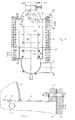
- the plate heat exchanger 10 shown in FIG. 1 consists of a plurality of plate packs 11, as indicated in FIG. 3.
- the plate packs 11 are held together by pressure holding plates 20, as shown in the lower parts of FIGS. 1 and 3.
- the plate packs 11 consist of embossed and / or corrugated plates which form corrugated channels 31 and tubular channels 32, as shown in detail in FIG. 5.
- the so-called shaft side which consists of corrugated and welded plates 34, extends transversely to the so-called pipe side, which consists of tubular plates 34.
- the wavy channels 31 are covered by a hood 14 and an end plate 15.
- the end plate 15 is held in rectangular flanges 13, which in turn with a Rectangular lid 12 are connected.
- the rectangular lid 12 is provided with a pipe-side connection 35.
- the rectangular cover 12 consists of normal structural steel and is provided on the inside with a thin cover lining 16 made of stainless steel.
- the hood 14 is provided with a connecting flange 19 on the shaft side.
- the shaft side in the area of the hood 14 is separated from the pipe side by a comb plate 17.
- the comb plate 17 is welded to the free end of the end plate 15 via a weld seam 18 in the region of a comb connection 33.
- the hood 14 is also welded to the face plate 15.
- the comb plate 17 is made of stainless steel and is made relatively thin compared to the end plate 15. It has only about a quarter of the thickness of the end plate 15.
- a negative pressure can occur in the hoods 14; therefore, as shown in FIG. 3, they are reinforced with inner support tubes 38.
- the support tubes 38 are connected in welds 39 to support tube reinforcement plates 37. With the support tube reinforcement plates 37, the support tubes 38 are held on the relatively thin side plates 22.
- the side plates 22 are made of stainless steel and, as FIG. 3 shows in their lower part, are held by the more solid pressure-holding plates 20, which consist of a normal structural steel.
- FIG. 5 further shows, screw sleeves 21 extending in front of the plate packs 11 are guided through the side plates 22.
- the screw sleeves 21 are welded at the ends with welds 26 to the relatively thin side plates 22.
- the side plates 22 are made of stainless steel and are practically only a cladding for the stronger pressure holding plates 20 arranged behind them, which are made of normal structural steel, so-called black material.
- Tension bolts 23 are guided through the screw sleeves 21 and hold the pressure holding plates 20 lying opposite one another via nuts 24 against the side plates 22 or the plate packs 11.
- the nuts 24 are supported via washers 25 in the bores 36 of the pressure holding plates 20.
- the bores 36 have a larger diameter than corresponds to the outer diameters of the screw sleeves 21 in order to keep the pressure holding plates 20 free of the weld seams 26 of the stainless steel side plates 22.
- lateral deflection plates 27 and 29 are provided between the plate packs 11 and the rectangular flanges 13.
- the first, somewhat larger baffle plates 27, as shown in FIG. 7, are connected at one end to the screw sleeves 21 via weld seams 30a.
- the other free ends are held freely in the area of the rectangular flange 13 in V-shaped deflection profiles 28.
- the deflection plates 27 are thus freely movable at one end and can deflect.
- baffle plates 29 are held at one end by the comb-shaped plate packs 11.
- the baffle plates 29 are connected to a weld 30 with the same screw sleeves 21 as the larger baffle plates 27 are connected.
Landscapes
- Engineering & Computer Science (AREA)
- Physics & Mathematics (AREA)
- Thermal Sciences (AREA)
- Mechanical Engineering (AREA)
- General Engineering & Computer Science (AREA)
- Heat-Exchange Devices With Radiators And Conduit Assemblies (AREA)
Abstract
Description
- Die Erfindung betrifft einen Plattenwärmetauscher, bestehend aus einem Plattenpaket mit einer Vielzahl unter Bildung wellenförmiger und rohrförmiger Kanäle geprägter und/oder gewellter Platten, in denen im Kreuzgegenstrom wärmezuübertragende, strömende Medien aneinander vorbeiführbar sind, und die Plattenpakete durch Druckhalteplatten und zwischen diesen querverlaufende, in Schraubhülsen geführte Zugankerschrauben zusammengehalten sind.
- Derartige Plattenwärmetauscher sind allgemein bekannt und dienen dazu, zwei voneinander getrennte Medien mit unterschiedlichen Temperaturen einander vorbei zu führen. Die Medien, beispielsweise ein heißes Gas und eine kältere Kühlflüssigkeit, werden dabei im sogenannten Kreuzgegenstrom aneinander vorbeigeführt. Zwischen den Wellblechen und den hohlen Wandungen findet dabei ein Wärmeübergang statt. Da die strömenden Medien üblicherweise recht aggressiv sind und eine Korrosion der Plattenpakete bewirken können, sind sie aus Edelstahl gefertigt - Edelstahl aber ist relativ teuer und äußerst schwierig zu ver- und bearbeiten.
- Aufgabe der vorliegenden Erfindung ist es, den Edelstahlanteil bei einem Plattenwärmetauscher der eingangs beschriebenen Art zu verringern, die Verarbeitung zu erleichtern und die Funktionssicherheit zu gewährleisten.
- Gelöst wird die Aufgabe dadurch, daß die wellenförmigen Kanäle und die rohrförmigen Kanäle durch Kammbleche voneinander getrennt sind, die Kammbleche über Kammeinbindungen mit den Stirnblechen verschweißt sind, die Plattenpakete beidseitig mit Seitenblechen abgedichtet sind, die Seitenbleche von Druckhalteplatten gehalten und abgestützt sind und die Schraubhülsen mit den Seitenblechen verschweißt sind.
- Durch diese Maßnahmen wird ein Plattenwärmetauscher geschaffen, bei dem die Edelstahlbauteile keine tragende Funktion mehr auszuüben haben. Die Edelstahlanteile dienen lediglich dem eigentlichen Korrosionsschutz, während die Festigkeits- und Stabilitätsaufgaben durch sogenanntes Schwarzmaterial, daß heißt Baustahl wie ST37, ST52 usw. gefertigt werden können. Das aus dünnwandigen Platten mit einer Wanddicke von ca. 0,8 mm bestehende Plattenpaket ist mit ebenfalls dünnwandigen Seitenblechen zu einer Einheit verschweißt.
- Da die Druckhalteplatten mit dieser Einheit nicht verschweißt sondern verschraubt sind, kann sie sich bei Wärmeeinwirkung frei ausdehnen. Dadurch können sehr hohe Temperaturdifferenzen sowohl zwischen den beiden aneinander vorbei geführten Medien als auch zwischen dem Medium und der Umgebung aufgenommen werden. Ein solcher Plattenwärmetauscher kann dadurch bei gleicher Funktionssicherheit und Korrosionsbeständigkeit auch für Medien mit sehr hohen Temperaturen und Temperaturdifferenzen eingesetzt werden.
- Weitere vorteilhafte Maßnahmen sind in den Unteransprüchen beschrieben. Die Erfindung ist in der beiliegenden Zeichnung dargestellt und wird nachfolgend näher beschrieben; es zeigt:
- Figur 1
- die Seitenansicht, teilweise ohne und teilweise mit Druckhalteplatten, eines erfindungsgemäßen Plattenwärmetauschers, mit durch eine Haube abgedeckter Seite der wellenförmigen Kanalmündungsseite, die mit einer Edelstahl-Kammblechabtren nung gegenüber der Rohrseite verschweißt ist, aus Schwarzmaterial besteht und mit innenseitigen Stützrohren versehen ist;
- Figur 2
- die Detaildarstellung der EdelstahlKammblechabdeckung gemäß dem Ausschnitt II in der Figur 1;
- Figur 3
- die Vorderansicht eines Plattenwärmetauschers nach der Figur 1, dargestellt teilweise ohne und teilweise mit Druckhalteplatten, mit zwischen den beidseitigen Druckhalteplatten angeordneten Plattenpaketen, die durch in Schraubhülsen verlaufenden Zugankerschrauben miteinander verbunden sind, und mit durch innere Stützrohre abgestützten wellenseitigen Hauben;
- Figur 4
- die Detaildarstellung eines inneren Stützrohres zur Abstützung der wellenseitigen Hauben eines Plattenwärmetauschers gemäß dem Ausschnitt IV in der Figur 3;
- Figur 5
- die Einzelheit "Z" in der Figur 3, mit Darstellung der Verbindung zwischen den dünnen Edelstahl-Seitenblechen und den Schraubhülsen, die von Druckhalteplatten aus Schwarzmaterial gehalten werden;
- Figur 6
- die Draufsicht auf einen Plattenwärmetauscher nach der Figur 1, teilweise geschnitten, mit an einer Schraubhülse verschweißten Umlenkblechen;
- Figur 7
- den Schnitt gemäß der Linie VII-VII in der Figur 6 in Draufsicht.
- Der in der Figur 1 dargestellte Plattenwärmetauscher 10 besteht aus einer Vielzahl von Plattenpaketen 11, wie sie in der Figur 3 angedeutet sind. Die Plattenpakete 11 werden von Druckhalteplatten 20 zusammengehalten, wie sie in den unteren Teilen der Figuren 1 und 3 dargestellt sind.
- Die Plattenpakete 11 bestehen aus geprägten und/oder gewellten Platten, die wellenförmige Kanäle 31 und rohrförmige Kanäle 32 bilden, wie sie in der Figur 5 im Detail dargestellt sind. Dabei verläuft die sog. Wellenseite, die aus wellenförmig geprägten und zusammengeschweißten Platten 34 besteht quer zu der sog. Rohrseite, die aus rohrförmig geprägten Platten 34 besteht.
- Die wellenförmigen Kanäle 31 sind durch eine Haube 14 und ein Stirnblech 15 abgedeckt. Das Stirnblech 15 ist in Rechteckflanschen 13 gehalten, die wiederum mit einem Rechteckdeckel 12 verbunden sind. Der Rechteckdeckel 12 ist mit einem rohrseitigen Anschluß 35 versehen. Der Rechteckdeckel 12 besteht aus normalem Baustahl und ist auf der Innenseite mit einer dünnen Deckelauskleidung 16 aus Edelstahl versehen. Die Haube 14 ist mit einem wellenseitigen Anschlußflansch 19 versehen.
- Wie die Figur 2 zeigt, ist die Wellenseite im Bereich der Haube 14 durch ein Kammblech 17 von der Rohrseite abgetrennt. Das Kammblech 17 ist über eine Schweißnaht 18 im Bereich einer Kammeinbindung 33 mit dem freien Ende des Stirnbleches 15 verschweißt. Die Haube 14 ist ebenfalls mit dem Stirnblech 15 verschweißt. Das Kammblech 17 besteht aus Edelstahl und ist relativ dünn gegenüber den Stirnblech 15 ausgeführt. Es weist nur etwa ein Viertel der Stärke des Stirnbleches 15 auf.
- In den Hauben 14 kann ein Unterdruck auftreten; sie sind deshalb, wie die Figur 3 zeigt, mit innen verlaufenden Stützrohren 38 verstärkt. Wie die Figur 4 im Detail zeigt, sind die Stützrohre 38 in Schweißungen 39 mit Stützrohrverstärkungsblechen 37 verbunden. Mit den Stützrohrverstärkungsblechen 37 sind die Stützrohre 38 an den relativ dünnen Seitenblechen 22 gehalten. Die Seitenbleche 22 bestehen aus Edelstahl und werden, wie die Figur 3 in ihrem unteren Teil zeigt, von den massiveren Druckhalteplatten 20 gehalten, die aus einem normalen Baustahl bestehen.
- Wie die Figur 5 weiter zeigt, sind vor den Plattenpaketen 11 verlaufende Schraubhülsen 21 durch die Seitenbleche 22 geführt. Die Schraubhülsen 21 sind endseitig mit Schweißnähten 26 mit den relativ dünnen Seitenblechen 22 verschweißt. Die Seitenbleche 22 bestehen aus Edelstahl und sind praktisch lediglich eine Plattierung für die dahinter angeordneten stärkeren Druckhalteplatten 20, die aus normalen Baustahl, sog. Schwarzmaterial, gefertigt sind.
- Durch die Schraubhülsen 21 sind Zugankerschrauben 23 geführt, die die einander gegenüberliegenden Druckhalteplatten 20 über Muttern 24 gegen die Seitenbleche 22 bzw. die Plattenpakete 11 halten. Die Muttern 24 stützen sich dabei über Ansatzscheiben 25 in den Bohrungen 36 der Druckhalteplatten 20 ab. Die Bohrungen 36 weisen einen größeren Durchmesser auf, als es den Außendurchmessern der Schraubhülsen 21 entspricht, um die Druckhalteplatten 20 von den Schweißnähten 26 der Edelstahlseitenbleche 22 frei zu halten.
- Wie die Figuren 6 und 7 zeigen, sind zwischen den Plattenpaketen 11 und den Rechteckflanschen 13 seitliche Umlenkbleche 27 und 29 vorgesehen. Die ersten, etwas größeren Umlenkbleche 27 sind, wie die Figur 7 zeigt, an einem Ende über Schweißnähte 30a mit den Schraubhülsen 21 verbunden. Die anderen freien Enden sind im Bereich des Rechteckflansches 13 frei in V-förmigen Umlenkprofilen 28 gehalten. Die Umlenkbleche 27 sind dadurch mit einem Ende frei beweglich und können einfedern.
- Die zweiten, etwas kleineren Umlenkbleche 29 sind an einem Ende von dem kammförmigen Plattenpaketen 11 gehalten. Auf der anderen Seite sind die Umlenkbleche 29 mit einer Schweißnaht 30 mit den gleichen Schraubhülsen 21 verbunden, wie auch die größeren Umlenkbleche 27 verbunden sind.
-
- 10
- Plattenwärmetauscher
- 11
- Plattenpaket
- 12
- Rechteckdeckel
- 13
- Rechteckflansch
- 14
- Haube
- 15
- Stirnblech
- 16
- Deckelauskleidung
- 17
- Kammblech
- 18
- Schweißnaht
- 19
- wellenseitiger Anschlußflansch
- 20
- Druckhalteplatte
- 21
- Schraubhülse
- 22
- Seitenblech
- 23
- Zugankerschraube
- 24
- Mutter
- 25
- Ansatzscheibe
- 26
- Schweißnaht
- 27
- Umlenkblech
- 28
- Umlenkprofil
- 29
- Umlenkblech
- 30, 30a
- Schweißnaht
- 31
- wellenförmiger Kanal
- 32
- rohrförmiger Kanal
- 33
- Kammeinbindung
- 34
- Platte
- 35
- rohrseitiger Anschluß
- 36
- Bohrung
- 37
- Stützrohrverstärkungsblech
- 38
- Stützrohr
- 39
- Schweißung
Claims (10)
- Plattenwärmetauscher (10), bestehend aus einem Plattenpaket (11) mit einer Vielzahl unter Bildung wellenförmiger und rohrförmiger Kanäle (31, 32) geprägter und/oder gewellter Platten (34), in denen im Kreuzgegenstrom wärmezuübertragende, strömende Medien aneinander vorbeiführbar sind, wobei die Plattenpakete (11) durch Druckhalteplatten (20) und zwischen diesen querverlaufende, in Schraubhülsen (21) geführte Zugankerschrauben (23) zusammengehalten sind, dadurch gekennzeichnet, daß die wellenförmigen Kanäle (31) und die rohrförmigen Kanäle (32) durch Kammbleche (17) voneinander getrennt sind, die Kammbleche (17) über Kammeinbindungen (33) mit den Stirnblechen (15) verschweißt sind, die Plattenpakete (11) beidseitig mit Seitenblechen (22) abgedichtet sind, die Seitenbleche (22) von Druckhalteplatten (20) gehalten und abgestützt sind und die Schraubhülsen (21) mit den Seitenblechen (22) verschweißt sind.
- Plattenwärmetauscher nach Anspruch 1, dadurch gekennzeichnet, daß die Kammbleche (17) und die Seitenbleche (22) aus Edelstahl bestehen.
- Plattenwärmetauscher nach den Ansprüchen 1 und 2, dadurch gekennzeichnet, daß die Edelstahl-Kammbleche (17) im Plasma-Schweißverfahren ausgeschnitten sind.
- Plattenwärmetauscher nach den Ansprüchen 1 bis 3, dadurch gekennzeichnet, daß die Druckhalteplatten (20) und die Seitenbleche (22) miteinander unverbunden sind.
- Plattenwärmetauscher nach den Ansprüchen 1 bis 4, dadurch gekennzeichnet, daß zwischen den Plattenpaketen (11) und dem gegenüberliegenden Rechteckflansch (12) Umlenkbleche (27, 29) vorgesehen sind.
- Plattenwärmertauscher nach den Ansprüchen 1 bis 5, dadurch gekennzeichnet, daß die Umlenkbleche (29) kammförmig ausgebildet und jeweils mit einer Schraubhülse (21) verschweißt sind.
- Plattenwärmetauscher nach den Ansprüchen 1 bis 6, dadurch gekennzeichnet, daß ein erstes Umlenkblech (27) an seinem einen freien Ende mit einer Schraubhülse (21) verschweißt und an seinem anderen freien Ende in einem V-förmigen Umlenkprofil (28) unverbunden gehalten ist.
- Plattenwärmetauscher nach den Ansprüchen 1 bis 7, dadurch gekennzeichnet, daß ein zweites Umlenkblech (29) an seinem einen freien Ende mit einer Schraubhülse (21) verschweißt und an seinem anderen freien Ende von dem kammförmigen Plattenpakete (11) gehalten ist.
- Plattenwärmetauscher nach einem der Ansprüche 1 bis 8, dadurch gekennzeichnet, daß die Kanäle (31, 32) mit jeweils einer gemeinsamen Haube (14) abgedeckt und in den Hauben (14) Stützrohre (38) vorgesehen sind.
- Plattenwärmetauscher nach Anspruch 9, dadurch gekennzeichnet, daß die in den Hauben (14) vorgesehenen Stützrohre (38) mit Stützrohrverstärkungsblechen (37) an den relativ dünnenwandigen Seitenblechen (22) gehalten sind.
Applications Claiming Priority (2)
| Application Number | Priority Date | Filing Date | Title |
|---|---|---|---|
| DE19620543A DE19620543C2 (de) | 1996-04-19 | 1996-05-22 | Hybrid-Plattenwärmetauscher |
| DE19620543 | 1996-05-22 |
Publications (3)
| Publication Number | Publication Date |
|---|---|
| EP0809081A2 true EP0809081A2 (de) | 1997-11-26 |
| EP0809081A3 EP0809081A3 (de) | 1999-03-10 |
| EP0809081B1 EP0809081B1 (de) | 2004-01-28 |
Family
ID=7794973
Family Applications (1)
| Application Number | Title | Priority Date | Filing Date |
|---|---|---|---|
| EP97250157A Expired - Lifetime EP0809081B1 (de) | 1996-05-22 | 1997-05-16 | Hybrid-Plattenwärmetauscher |
Country Status (2)
| Country | Link |
|---|---|
| EP (1) | EP0809081B1 (de) |
| AT (1) | ATE258673T1 (de) |
Cited By (1)
| Publication number | Priority date | Publication date | Assignee | Title |
|---|---|---|---|---|
| WO2009152830A1 (de) * | 2008-06-18 | 2009-12-23 | Gesmex Gmbh | Umrüstsatz für einen rohrbündelwärmetauscher |
Family Cites Families (5)
| Publication number | Priority date | Publication date | Assignee | Title |
|---|---|---|---|---|
| DE1751976A1 (de) * | 1968-08-27 | 1971-09-16 | Linde Ag | Plattenwaermeaustauscher |
| DE4031436A1 (de) * | 1990-10-04 | 1992-04-09 | Bavaria Anlagenbau Gmbh | Plattenwaermetauscher-modul |
| GB9104156D0 (en) * | 1991-02-27 | 1991-04-17 | Rolls Royce & Ass | Heat exchanger |
| FR2702978B1 (fr) * | 1993-03-26 | 1995-07-13 | Barriquand Echangeurs | Procédé d'assemblage de brides ou analogues de raccordement sur un faisceau d'échangeur et échangeur en faisant application. |
| DE4422283C1 (de) * | 1994-06-25 | 1995-09-28 | Balcke Duerr Ag | Verfahren zum Verschweißen von kammartigen Abdichtleisten an Plattenwärmetauschern |
-
1997
- 1997-05-16 EP EP97250157A patent/EP0809081B1/de not_active Expired - Lifetime
- 1997-05-16 AT AT97250157T patent/ATE258673T1/de not_active IP Right Cessation
Non-Patent Citations (1)
| Title |
|---|
| None |
Cited By (2)
| Publication number | Priority date | Publication date | Assignee | Title |
|---|---|---|---|---|
| WO2009152830A1 (de) * | 2008-06-18 | 2009-12-23 | Gesmex Gmbh | Umrüstsatz für einen rohrbündelwärmetauscher |
| US9080815B2 (en) | 2008-06-18 | 2015-07-14 | Gesmex Gmbh | Conversion set for a tube bundle heat exchanger |
Also Published As
| Publication number | Publication date |
|---|---|
| EP0809081A3 (de) | 1999-03-10 |
| ATE258673T1 (de) | 2004-02-15 |
| EP0809081B1 (de) | 2004-01-28 |
Similar Documents
| Publication | Publication Date | Title |
|---|---|---|
| EP0772018B1 (de) | Wärmeübertrager zum Kühlen von Abgas | |
| EP2304370B1 (de) | Umrüstsatz für einen rohrbündelwärmetauscher | |
| DE2810275A1 (de) | Waermetauscher | |
| DE4433165C1 (de) | Wärmetauscher in Plattenbauweise | |
| DE3840460C2 (de) | ||
| DE3028563A1 (de) | Abhitzekessel | |
| EP0134012B1 (de) | Profilrohr-Wärmetauscher | |
| EP1154218A1 (de) | Plattenwärmetauscher | |
| DE2846549A1 (de) | Waermeaustauscher mit rohrschlangen, die zwischen zwei tragwaenden angeordnet sind | |
| DE3701614C2 (de) | Rohrwärmetauscher | |
| DE19547928C2 (de) | Plattenwärmetauscher | |
| DE69508575T2 (de) | Plattenwärmetauscher | |
| DE3803947C2 (de) | ||
| DE2706090A1 (de) | Plattenaustauscher | |
| EP0809081A2 (de) | Hybrid-Plattenwärmetauscher | |
| EP1995545B1 (de) | Plattenapparat für Wärmeübertragungsvorgänge | |
| DE19620543C2 (de) | Hybrid-Plattenwärmetauscher | |
| DE3911257C2 (de) | Wärmetauscher | |
| EP0053248A2 (de) | Wärmeaustauscher | |
| DE3734523A1 (de) | Ladeluftkuehler | |
| DE19735630C2 (de) | Wärmetauscher und Verfahren zu seiner Herstellung | |
| DE2733892B2 (de) | Rohrverbindung zwischen sich kreuzenden Rohren eines Register-Heizkörpers aus Aluminium | |
| EP1154216A1 (de) | Dampfbeheitzter Flüssigkeitserwärmer | |
| DE2236293C3 (de) | Wärmetauscher zur Rückkühlung der Kühlflüssigkeit von Transformatoren und Drosseln | |
| DE9204430U1 (de) | Rohrbündelwärmeaustauscher mit zweiwegigem Durchfluß |
Legal Events
| Date | Code | Title | Description |
|---|---|---|---|
| PUAI | Public reference made under article 153(3) epc to a published international application that has entered the european phase |
Free format text: ORIGINAL CODE: 0009012 |
|
| AK | Designated contracting states |
Kind code of ref document: A2 Designated state(s): AT CH DE FR GB IT LI SE |
|
| PUAL | Search report despatched |
Free format text: ORIGINAL CODE: 0009013 |
|
| AK | Designated contracting states |
Kind code of ref document: A3 Designated state(s): AT CH DE FR GB IT LI SE |
|
| 17P | Request for examination filed |
Effective date: 19990408 |
|
| 17Q | First examination report despatched |
Effective date: 20010411 |
|
| GRAP | Despatch of communication of intention to grant a patent |
Free format text: ORIGINAL CODE: EPIDOSNIGR1 |
|
| RAP1 | Party data changed (applicant data changed or rights of an application transferred) |
Owner name: APV THERMOTECH GMBH |
|
| GRAS | Grant fee paid |
Free format text: ORIGINAL CODE: EPIDOSNIGR3 |
|
| GRAA | (expected) grant |
Free format text: ORIGINAL CODE: 0009210 |
|
| AK | Designated contracting states |
Kind code of ref document: B1 Designated state(s): AT CH DE FR GB IT LI SE |
|
| REG | Reference to a national code |
Ref country code: GB Ref legal event code: FG4D Free format text: NOT ENGLISH |
|
| REG | Reference to a national code |
Ref country code: CH Ref legal event code: EP |
|
| REF | Corresponds to: |
Ref document number: 59711246 Country of ref document: DE Date of ref document: 20040304 Kind code of ref document: P |
|
| REG | Reference to a national code |
Ref country code: CH Ref legal event code: NV Representative=s name: KELLER & PARTNER PATENTANWAELTE AG |
|
| REG | Reference to a national code |
Ref country code: SE Ref legal event code: TRGR |
|
| GBT | Gb: translation of ep patent filed (gb section 77(6)(a)/1977) |
Effective date: 20040419 |
|
| ET | Fr: translation filed | ||
| PLBE | No opposition filed within time limit |
Free format text: ORIGINAL CODE: 0009261 |
|
| STAA | Information on the status of an ep patent application or granted ep patent |
Free format text: STATUS: NO OPPOSITION FILED WITHIN TIME LIMIT |
|
| 26N | No opposition filed |
Effective date: 20041029 |
|
| PGFP | Annual fee paid to national office [announced via postgrant information from national office to epo] |
Ref country code: SE Payment date: 20090528 Year of fee payment: 13 Ref country code: IT Payment date: 20090527 Year of fee payment: 13 Ref country code: FR Payment date: 20090518 Year of fee payment: 13 Ref country code: DE Payment date: 20090528 Year of fee payment: 13 Ref country code: AT Payment date: 20090505 Year of fee payment: 13 |
|
| PGFP | Annual fee paid to national office [announced via postgrant information from national office to epo] |
Ref country code: CH Payment date: 20090526 Year of fee payment: 13 |
|
| PGFP | Annual fee paid to national office [announced via postgrant information from national office to epo] |
Ref country code: GB Payment date: 20090528 Year of fee payment: 13 |
|
| REG | Reference to a national code |
Ref country code: CH Ref legal event code: PL |
|
| GBPC | Gb: european patent ceased through non-payment of renewal fee |
Effective date: 20100516 |
|
| PG25 | Lapsed in a contracting state [announced via postgrant information from national office to epo] |
Ref country code: AT Free format text: LAPSE BECAUSE OF NON-PAYMENT OF DUE FEES Effective date: 20100516 |
|
| EUG | Se: european patent has lapsed | ||
| REG | Reference to a national code |
Ref country code: FR Ref legal event code: ST Effective date: 20110131 |
|
| PG25 | Lapsed in a contracting state [announced via postgrant information from national office to epo] |
Ref country code: LI Free format text: LAPSE BECAUSE OF NON-PAYMENT OF DUE FEES Effective date: 20100531 Ref country code: CH Free format text: LAPSE BECAUSE OF NON-PAYMENT OF DUE FEES Effective date: 20100531 |
|
| PG25 | Lapsed in a contracting state [announced via postgrant information from national office to epo] |
Ref country code: SE Free format text: LAPSE BECAUSE OF NON-PAYMENT OF DUE FEES Effective date: 20100517 Ref country code: IT Free format text: LAPSE BECAUSE OF NON-PAYMENT OF DUE FEES Effective date: 20100516 |
|
| PG25 | Lapsed in a contracting state [announced via postgrant information from national office to epo] |
Ref country code: DE Free format text: LAPSE BECAUSE OF NON-PAYMENT OF DUE FEES Effective date: 20101201 |
|
| PG25 | Lapsed in a contracting state [announced via postgrant information from national office to epo] |
Ref country code: FR Free format text: LAPSE BECAUSE OF NON-PAYMENT OF DUE FEES Effective date: 20100531 |
|
| PG25 | Lapsed in a contracting state [announced via postgrant information from national office to epo] |
Ref country code: GB Free format text: LAPSE BECAUSE OF NON-PAYMENT OF DUE FEES Effective date: 20100516 |