EP0809050B1 - Verfahren zur Herstellung einen Kolben für eine Brennkraftmaschine - Google Patents
Verfahren zur Herstellung einen Kolben für eine Brennkraftmaschine Download PDFInfo
- Publication number
- EP0809050B1 EP0809050B1 EP97108160A EP97108160A EP0809050B1 EP 0809050 B1 EP0809050 B1 EP 0809050B1 EP 97108160 A EP97108160 A EP 97108160A EP 97108160 A EP97108160 A EP 97108160A EP 0809050 B1 EP0809050 B1 EP 0809050B1
- Authority
- EP
- European Patent Office
- Prior art keywords
- piston
- alloy
- interface
- less
- forging
- Prior art date
- Legal status (The legal status is an assumption and is not a legal conclusion. Google has not performed a legal analysis and makes no representation as to the accuracy of the status listed.)
- Expired - Lifetime
Links
- 238000002485 combustion reaction Methods 0.000 title claims description 25
- 238000004519 manufacturing process Methods 0.000 title claims description 18
- 239000000956 alloy Substances 0.000 claims description 119
- 229910045601 alloy Inorganic materials 0.000 claims description 115
- 238000005242 forging Methods 0.000 claims description 48
- 238000000034 method Methods 0.000 claims description 48
- 238000005304 joining Methods 0.000 claims description 40
- 239000000843 powder Substances 0.000 claims description 32
- 229910052782 aluminium Inorganic materials 0.000 claims description 13
- 238000001125 extrusion Methods 0.000 claims description 5
- 238000003754 machining Methods 0.000 claims description 4
- 238000002844 melting Methods 0.000 claims description 3
- 230000008018 melting Effects 0.000 claims description 3
- 238000003825 pressing Methods 0.000 claims description 3
- 238000009497 press forging Methods 0.000 claims 2
- 238000005520 cutting process Methods 0.000 claims 1
- XEEYBQQBJWHFJM-UHFFFAOYSA-N Iron Chemical compound [Fe] XEEYBQQBJWHFJM-UHFFFAOYSA-N 0.000 description 33
- 239000000463 material Substances 0.000 description 29
- 239000010949 copper Substances 0.000 description 24
- 239000011777 magnesium Substances 0.000 description 24
- 239000000203 mixture Substances 0.000 description 24
- 239000000835 fiber Substances 0.000 description 21
- HBMJWWWQQXIZIP-UHFFFAOYSA-N silicon carbide Chemical compound [Si+]#[C-] HBMJWWWQQXIZIP-UHFFFAOYSA-N 0.000 description 19
- 229910010271 silicon carbide Inorganic materials 0.000 description 19
- 229910000838 Al alloy Inorganic materials 0.000 description 17
- XUIMIQQOPSSXEZ-UHFFFAOYSA-N Silicon Chemical compound [Si] XUIMIQQOPSSXEZ-UHFFFAOYSA-N 0.000 description 16
- 239000010703 silicon Substances 0.000 description 16
- 229910052710 silicon Inorganic materials 0.000 description 16
- 239000011651 chromium Substances 0.000 description 15
- 239000011572 manganese Substances 0.000 description 15
- PXHVJJICTQNCMI-UHFFFAOYSA-N nickel Substances [Ni] PXHVJJICTQNCMI-UHFFFAOYSA-N 0.000 description 15
- 238000005275 alloying Methods 0.000 description 14
- XAGFODPZIPBFFR-UHFFFAOYSA-N aluminium Chemical compound [Al] XAGFODPZIPBFFR-UHFFFAOYSA-N 0.000 description 11
- PNEYBMLMFCGWSK-UHFFFAOYSA-N aluminium oxide Inorganic materials [O-2].[O-2].[O-2].[Al+3].[Al+3] PNEYBMLMFCGWSK-UHFFFAOYSA-N 0.000 description 11
- 229910052593 corundum Inorganic materials 0.000 description 11
- 229910001845 yogo sapphire Inorganic materials 0.000 description 11
- 239000004411 aluminium Substances 0.000 description 10
- 229910052582 BN Inorganic materials 0.000 description 9
- PZNSFCLAULLKQX-UHFFFAOYSA-N Boron nitride Chemical compound N#B PZNSFCLAULLKQX-UHFFFAOYSA-N 0.000 description 9
- RYGMFSIKBFXOCR-UHFFFAOYSA-N Copper Chemical compound [Cu] RYGMFSIKBFXOCR-UHFFFAOYSA-N 0.000 description 9
- FYYHWMGAXLPEAU-UHFFFAOYSA-N Magnesium Chemical compound [Mg] FYYHWMGAXLPEAU-UHFFFAOYSA-N 0.000 description 9
- 229910052802 copper Inorganic materials 0.000 description 9
- 229910052742 iron Inorganic materials 0.000 description 9
- 229910052749 magnesium Inorganic materials 0.000 description 9
- PMHQVHHXPFUNSP-UHFFFAOYSA-M copper(1+);methylsulfanylmethane;bromide Chemical compound Br[Cu].CSC PMHQVHHXPFUNSP-UHFFFAOYSA-M 0.000 description 8
- 229910000735 Pm alloy Inorganic materials 0.000 description 6
- 229910052751 metal Inorganic materials 0.000 description 6
- 239000002184 metal Substances 0.000 description 6
- CWQXQMHSOZUFJS-UHFFFAOYSA-N molybdenum disulfide Chemical compound S=[Mo]=S CWQXQMHSOZUFJS-UHFFFAOYSA-N 0.000 description 6
- 229910052982 molybdenum disulfide Inorganic materials 0.000 description 6
- 229910018084 Al-Fe Inorganic materials 0.000 description 5
- 229910018192 Al—Fe Inorganic materials 0.000 description 5
- 229910052961 molybdenite Inorganic materials 0.000 description 5
- 230000002093 peripheral effect Effects 0.000 description 5
- 229910018125 Al-Si Inorganic materials 0.000 description 3
- 229910018520 Al—Si Inorganic materials 0.000 description 3
- 239000000919 ceramic Substances 0.000 description 3
- 239000003795 chemical substances by application Substances 0.000 description 3
- 238000005253 cladding Methods 0.000 description 3
- 150000001875 compounds Chemical class 0.000 description 3
- 238000009749 continuous casting Methods 0.000 description 3
- 239000011159 matrix material Substances 0.000 description 3
- 239000000047 product Substances 0.000 description 3
- 230000002000 scavenging effect Effects 0.000 description 3
- 239000000654 additive Substances 0.000 description 2
- 238000005266 casting Methods 0.000 description 2
- 230000006835 compression Effects 0.000 description 2
- 238000007906 compression Methods 0.000 description 2
- 238000001816 cooling Methods 0.000 description 2
- 230000007423 decrease Effects 0.000 description 2
- 230000003247 decreasing effect Effects 0.000 description 2
- 238000009826 distribution Methods 0.000 description 2
- 239000000446 fuel Substances 0.000 description 2
- 150000002739 metals Chemical class 0.000 description 2
- 239000012779 reinforcing material Substances 0.000 description 2
- OKTJSMMVPCPJKN-UHFFFAOYSA-N Carbon Chemical compound [C] OKTJSMMVPCPJKN-UHFFFAOYSA-N 0.000 description 1
- VYZAMTAEIAYCRO-UHFFFAOYSA-N Chromium Chemical compound [Cr] VYZAMTAEIAYCRO-UHFFFAOYSA-N 0.000 description 1
- PWHULOQIROXLJO-UHFFFAOYSA-N Manganese Chemical compound [Mn] PWHULOQIROXLJO-UHFFFAOYSA-N 0.000 description 1
- ZOKXTWBITQBERF-UHFFFAOYSA-N Molybdenum Chemical compound [Mo] ZOKXTWBITQBERF-UHFFFAOYSA-N 0.000 description 1
- 235000014676 Phragmites communis Nutrition 0.000 description 1
- QCWXUUIWCKQGHC-UHFFFAOYSA-N Zirconium Chemical compound [Zr] QCWXUUIWCKQGHC-UHFFFAOYSA-N 0.000 description 1
- 230000000996 additive effect Effects 0.000 description 1
- 230000015572 biosynthetic process Effects 0.000 description 1
- 229910052799 carbon Inorganic materials 0.000 description 1
- 229910052804 chromium Inorganic materials 0.000 description 1
- 239000013078 crystal Substances 0.000 description 1
- 230000001419 dependent effect Effects 0.000 description 1
- 230000002542 deteriorative effect Effects 0.000 description 1
- 238000006073 displacement reaction Methods 0.000 description 1
- 230000005496 eutectics Effects 0.000 description 1
- 238000011049 filling Methods 0.000 description 1
- 239000012467 final product Substances 0.000 description 1
- 238000001192 hot extrusion Methods 0.000 description 1
- 239000004615 ingredient Substances 0.000 description 1
- 230000001788 irregular Effects 0.000 description 1
- 239000000314 lubricant Substances 0.000 description 1
- 229910052748 manganese Inorganic materials 0.000 description 1
- 229910001092 metal group alloy Inorganic materials 0.000 description 1
- 238000002156 mixing Methods 0.000 description 1
- 229910052750 molybdenum Inorganic materials 0.000 description 1
- 239000011733 molybdenum Substances 0.000 description 1
- 229910052759 nickel Inorganic materials 0.000 description 1
- TWNQGVIAIRXVLR-UHFFFAOYSA-N oxo(oxoalumanyloxy)alumane Chemical compound O=[Al]O[Al]=O TWNQGVIAIRXVLR-UHFFFAOYSA-N 0.000 description 1
- 230000000704 physical effect Effects 0.000 description 1
- 238000007747 plating Methods 0.000 description 1
- 230000001376 precipitating effect Effects 0.000 description 1
- 230000000630 rising effect Effects 0.000 description 1
- 238000005245 sintering Methods 0.000 description 1
- 238000007711 solidification Methods 0.000 description 1
- 238000004381 surface treatment Methods 0.000 description 1
- 238000003466 welding Methods 0.000 description 1
- 229910052726 zirconium Inorganic materials 0.000 description 1
Images


Classifications
-
- B—PERFORMING OPERATIONS; TRANSPORTING
- B22—CASTING; POWDER METALLURGY
- B22F—WORKING METALLIC POWDER; MANUFACTURE OF ARTICLES FROM METALLIC POWDER; MAKING METALLIC POWDER; APPARATUS OR DEVICES SPECIALLY ADAPTED FOR METALLIC POWDER
- B22F7/00—Manufacture of composite layers, workpieces, or articles, comprising metallic powder, by sintering the powder, with or without compacting wherein at least one part is obtained by sintering or compression
- B22F7/008—Manufacture of composite layers, workpieces, or articles, comprising metallic powder, by sintering the powder, with or without compacting wherein at least one part is obtained by sintering or compression characterised by the composition
-
- F—MECHANICAL ENGINEERING; LIGHTING; HEATING; WEAPONS; BLASTING
- F02—COMBUSTION ENGINES; HOT-GAS OR COMBUSTION-PRODUCT ENGINE PLANTS
- F02B—INTERNAL-COMBUSTION PISTON ENGINES; COMBUSTION ENGINES IN GENERAL
- F02B61/00—Adaptations of engines for driving vehicles or for driving propellers; Combinations of engines with gearing
- F02B61/04—Adaptations of engines for driving vehicles or for driving propellers; Combinations of engines with gearing for driving propellers
- F02B61/045—Adaptations of engines for driving vehicles or for driving propellers; Combinations of engines with gearing for driving propellers for marine engines
-
- F—MECHANICAL ENGINEERING; LIGHTING; HEATING; WEAPONS; BLASTING
- F02—COMBUSTION ENGINES; HOT-GAS OR COMBUSTION-PRODUCT ENGINE PLANTS
- F02F—CYLINDERS, PISTONS OR CASINGS, FOR COMBUSTION ENGINES; ARRANGEMENTS OF SEALINGS IN COMBUSTION ENGINES
- F02F3/00—Pistons
- F02F3/0015—Multi-part pistons
- F02F3/003—Multi-part pistons the parts being connected by casting, brazing, welding or clamping
-
- F—MECHANICAL ENGINEERING; LIGHTING; HEATING; WEAPONS; BLASTING
- F16—ENGINEERING ELEMENTS AND UNITS; GENERAL MEASURES FOR PRODUCING AND MAINTAINING EFFECTIVE FUNCTIONING OF MACHINES OR INSTALLATIONS; THERMAL INSULATION IN GENERAL
- F16J—PISTONS; CYLINDERS; SEALINGS
- F16J9/00—Piston-rings, e.g. non-metallic piston-rings, seats therefor; Ring sealings of similar construction
- F16J9/12—Details
- F16J9/22—Rings for preventing wear of grooves or like seatings
-
- F—MECHANICAL ENGINEERING; LIGHTING; HEATING; WEAPONS; BLASTING
- F02—COMBUSTION ENGINES; HOT-GAS OR COMBUSTION-PRODUCT ENGINE PLANTS
- F02B—INTERNAL-COMBUSTION PISTON ENGINES; COMBUSTION ENGINES IN GENERAL
- F02B75/00—Other engines
- F02B75/02—Engines characterised by their cycles, e.g. six-stroke
- F02B2075/022—Engines characterised by their cycles, e.g. six-stroke having less than six strokes per cycle
- F02B2075/025—Engines characterised by their cycles, e.g. six-stroke having less than six strokes per cycle two
-
- F—MECHANICAL ENGINEERING; LIGHTING; HEATING; WEAPONS; BLASTING
- F02—COMBUSTION ENGINES; HOT-GAS OR COMBUSTION-PRODUCT ENGINE PLANTS
- F02B—INTERNAL-COMBUSTION PISTON ENGINES; COMBUSTION ENGINES IN GENERAL
- F02B75/00—Other engines
- F02B75/02—Engines characterised by their cycles, e.g. six-stroke
- F02B2075/022—Engines characterised by their cycles, e.g. six-stroke having less than six strokes per cycle
- F02B2075/027—Engines characterised by their cycles, e.g. six-stroke having less than six strokes per cycle four
-
- F—MECHANICAL ENGINEERING; LIGHTING; HEATING; WEAPONS; BLASTING
- F02—COMBUSTION ENGINES; HOT-GAS OR COMBUSTION-PRODUCT ENGINE PLANTS
- F02F—CYLINDERS, PISTONS OR CASINGS, FOR COMBUSTION ENGINES; ARRANGEMENTS OF SEALINGS IN COMBUSTION ENGINES
- F02F3/00—Pistons
- F02F3/0015—Multi-part pistons
- F02F3/003—Multi-part pistons the parts being connected by casting, brazing, welding or clamping
- F02F2003/0061—Multi-part pistons the parts being connected by casting, brazing, welding or clamping by welding
-
- F—MECHANICAL ENGINEERING; LIGHTING; HEATING; WEAPONS; BLASTING
- F02—COMBUSTION ENGINES; HOT-GAS OR COMBUSTION-PRODUCT ENGINE PLANTS
- F02F—CYLINDERS, PISTONS OR CASINGS, FOR COMBUSTION ENGINES; ARRANGEMENTS OF SEALINGS IN COMBUSTION ENGINES
- F02F2200/00—Manufacturing
- F02F2200/04—Forging of engine parts
-
- F—MECHANICAL ENGINEERING; LIGHTING; HEATING; WEAPONS; BLASTING
- F05—INDEXING SCHEMES RELATING TO ENGINES OR PUMPS IN VARIOUS SUBCLASSES OF CLASSES F01-F04
- F05C—INDEXING SCHEME RELATING TO MATERIALS, MATERIAL PROPERTIES OR MATERIAL CHARACTERISTICS FOR MACHINES, ENGINES OR PUMPS OTHER THAN NON-POSITIVE-DISPLACEMENT MACHINES OR ENGINES
- F05C2201/00—Metals
- F05C2201/02—Light metals
- F05C2201/021—Aluminium
-
- Y—GENERAL TAGGING OF NEW TECHNOLOGICAL DEVELOPMENTS; GENERAL TAGGING OF CROSS-SECTIONAL TECHNOLOGIES SPANNING OVER SEVERAL SECTIONS OF THE IPC; TECHNICAL SUBJECTS COVERED BY FORMER USPC CROSS-REFERENCE ART COLLECTIONS [XRACs] AND DIGESTS
- Y10—TECHNICAL SUBJECTS COVERED BY FORMER USPC
- Y10T—TECHNICAL SUBJECTS COVERED BY FORMER US CLASSIFICATION
- Y10T29/00—Metal working
- Y10T29/49—Method of mechanical manufacture
- Y10T29/49229—Prime mover or fluid pump making
- Y10T29/49249—Piston making
- Y10T29/49252—Multi-element piston making
-
- Y—GENERAL TAGGING OF NEW TECHNOLOGICAL DEVELOPMENTS; GENERAL TAGGING OF CROSS-SECTIONAL TECHNOLOGIES SPANNING OVER SEVERAL SECTIONS OF THE IPC; TECHNICAL SUBJECTS COVERED BY FORMER USPC CROSS-REFERENCE ART COLLECTIONS [XRACs] AND DIGESTS
- Y10—TECHNICAL SUBJECTS COVERED BY FORMER USPC
- Y10T—TECHNICAL SUBJECTS COVERED BY FORMER US CLASSIFICATION
- Y10T29/00—Metal working
- Y10T29/49—Method of mechanical manufacture
- Y10T29/49229—Prime mover or fluid pump making
- Y10T29/49249—Piston making
- Y10T29/49256—Piston making with assembly or composite article making
Definitions
- This invention relates to a method of making a piston for internal combustion engines according to the preamble of claim 1. Such a method is known from JP 01 180 927 A, JP 63 132 743 A or FR 1 226 350.
- An internal combustion engine piston in general is required to meet the following requirements.
- the piston is light-weight.
- the piston (i) has a thin-walled form (using a material of a high fatigue strength at high temperatures even with a thin wall and of a good forming property even with a thin wall), and (ii) is made of a material of a small density (a light material).
- the height of the top land, the portion above the piston ring, of the piston head is small. This is required for increasing compression ratio resulting in a higher performance and for smaller crevice volume resulting in reduced amount of unburned gas as an effective measure for reducing exhaust emissions.
- the head portion is made less likely to bend (the head portion is made thick-walled, and a material is used that retains a high Young's modulus even at a temperature of about 350 degrees C on the piston top surface).
- the piston for internal combustion engines is required to have high fatigue strength, proof strength, and hardness at high temperatures and to be made of a material that enables a thin-walled form and has good forming property.
- the first of them is to constitute the head and skirt portions with cladding materials of different physical properties (aluminium alloy and a compound layer made of aluminium alloy mixed with whiskers, short fibers, etc. (FRM)). Both materials are joined together by forging to form a single piston for internal combustion engines (Refer to the Japanese Laid-open Patent Application Sho-63-132743).
- the second is to make a two-layer body by powder-forming quenched powder aluminium matrices (powder metal) of a common composition with different ceramic powder mixing ratios.
- the two-layer body is then heat-pressed to form a pre-form.
- the pre-form is then heat-forged to form a piston for internal combustion engines, with the head portion containing a higher ratio of ceramic powder and the skirt portion containing a lower ratio of ceramic powder (Refer to the Japanese Laid-open Patent Application Hei-1-180927).
- the third is a piston for internal combustion engines, in which the head portion is made of forged powder metal or FRM, the skirt portion is made of an aluminium alloy casting, and both portions are welded together (Refer to the Japanese Laid-open Patent Application Hei-2-107749).
- a piston for an internal combustion engine as defined in the preamble of claim 1 is known from EP-A2-0 035 348.
- the piston known from this prior art document comprises a head portion made of compacted and sintered aluminum alloy powder which is shaped under heat and pressure and which is bonded to the skirt portion under heat and pressure.
- EP-A2-0 153 473 discloses a cast piston made of aluminum.
- the aluminum alloy may contain silicon.
- compressive strain induced by forging may cause the material forming the piston to crack.
- the FRM stress concentrations occur on interfaces between the matrix and the reinforcing materials of whiskers or short fibers, and therefore a sufficient fatigue strength cannot be provided at high temperatures.
- the cladding materials are used for forging. the processes become complicated and, as a result, the manufacturing cost increases.
- Another problem with the cladding material is that the material cannot be used locally, for example only in part of the head portion, in the ring groove portion where the piston ring is fit, or in the upper edge portion.
- the interface between the head portion and the skirt portion is enlarged.
- the joining strength at the interface between the head portion and the skirt portion may not be sufficient in particular if one of the portions has formed thereon an oxide layer which inhibits an intimate joint when bonding together the two portions under heat and pressure.
- the invention has been made in view of the disadvantages of the prior art described above with an object to provides a method of making an improved piston for internal combustion engines.
- the present invention provides a method as defined in claim 1.
- Preferred embodiments of the inventive method are set out in the dependent claims.
- the top length portion of the piston can be made thin-walled and light-weight
- the output can be increased by the increase in the compression ratio within the combustion chamber.
- Unbumed HC gas emissions are reduced by the decrease in crevice volume to serve as emission measures.
- the weight of the bearing area can be reduced and its durability be improved due to the reduction of inertial forces. Furthermore, by these measures engine vibrations can be reduced.
- FIG. 1 is a rough explanatory view of a two-cycle engine in which the internal combustion engine piston of the invention is used.
- the constitution and operation of the two-cycle engine 1 are as follows.
- a piston 3 moves up from the bottom dead center within a cylinder 2, a negative pressure is produced within a crankcase 4.
- Fuel from an injector 5 and air from an intake passage G form a mixture which is drawn through a reed valve 7 into the crankcase 4 and at the same time, a main scavenging port 8 and a sub-scavenging port 8 are covered with the piston 3.
- an exhaust port 9 is covered with the piston 3 and the mixture in the cylinder 2 is compressed.
- a spark is thrown off an ignition plug 10
- the mixture burns and produces pressure to push down the piston 3 within the cylinder.
- FIG. 2 is a rough explanatory view of a four-cycle engine in which the internal combustion engine piston of the invention is used.
- the constitution and operation of the four-cycle engine 20 are as follows.
- a piston 22 moves down from the top dead center within a cylinder 21, a negative pressure is produced in the cylinder 21.
- an intake valve 23 opens to draw a mixture of fuel from an injector 24 and air coming through an intake passage 25 into the cylinder 21.
- the intake and exhaust valves 23 and 26 are both closed and the mixture drawn into the cylinder 21 is compressed.
- the four-cycle engine 20 operating in the principle described above completes one combustion cycle as the piston 22 completes two reciprocations and a crankshaft 32 makes two turns in cooperation with a piston pin 29, a connecting rod 30, and a crank arm 31.
- the rotation of the crankshaft 32 for example of a motorcycle, is transmitted through the chain to the rear wheel.
- the amount of the mixture is increased or decreased by adjusting the opening of a throttle valve 33 interposed in the intake passage 25.
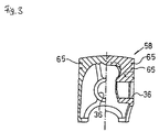
- FIG. 3 is a cross-sectional view of an example of an internal combustion engine piston 58 of the invention, with the left half showing a front view of a piston boss 36 below a piston ring groove 65 and the right half showing a side view of the piston boss 36.
- piston pin supporting strength is increased by increasing the piston wall thickness on the piston boss 36 side.
- the skirt portion (piston side portion) continued from the head portion to constitute the piston top surface is gradually thinned downward.
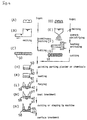
- FIG. 4 is an explanatory drawing to show the manufacturing process sequence for the internal combustion engine piston of FIG. 3. An example of the manufacturing method for the internal combustion engine piston of the invention will be described in reference to the drawings.
- an alloy ingot for the skirt portion comprising aluminium (Al), silicon (Si), copper (Cu), and magnesium (Mg) is prepared.
- the silicon is added for increasing resistance to wear and seizure required of the sliding surface of the piston skirt portion by precipitating hard initial or eutectic crystals in the metallic composition.
- the copper and magnesium are added for increasing alloy strength at high temperatures.
- the contents of additives are preferably; 5 - 25 % of silicon. 0.5 - 5 % of copper, and 0.5 - 1.5 % of magnesium. Outside such ranges, intended resistance to wear and seizure, and high temperature strength cannot be provided.
- those ingredients may be prepared in the form of separate ingots or powder and mixed and melted together.
- the ingot is melted and a block for the skirt portion is made by continuous casting or extrusion forming.
- the Al-Si-based alloy block formed in this way is lower in high temperature deformation resistance than the Al-Fe-based alloy block as will be described later (Proof strength of Al-Si-based alloy block at 400 degrees C is about 50 % of that of Al-Fe-based alloy block) and good forming property is provided for the thin wall portion.
- the block is cut to the size required for the skirt portion to form a piston alloy piece 50.
- an alloy ingot for the head portion comprising aluminium (Al), iron (Fe), and silicon (Si) is prepared.
- the iron is added for increasing fatigue strength at temperatures above 200 degrees C by dispersing metallic composition.
- the silicon is added for increasing resistance to wear and seizure as described above and further increasing ductility and lowering the melting point. Therefore, too much amount of silicon added causes excessive ductility and a lower strength. Also the lowered melting point results in a lower heat resistance. Therefore, it is necessary to add only minimum amount of silicon necessary for the forming property and wear resistance of the head portion to prevent the strength and heat resistance from lowering.
- the additive rate of iron in the head alloy is preferably 5 % or more, and that of silicon is 5 % or less.
- the ingot is melted, and quench-solidified at a cooling speed of 100 degrees C per second to make Al-Fe-based alloy powder.
- the powder is formed and solidified, and further hot-extruded.
- a quenched powder aluminium alloy block obtained in this way provides a uniform metallic composition free from parts which could cause stress concentrations while providing a high fatigue strength. This is because, unlike the cooling in the ordinary casting in which coarse iron composition is produced in the alloy and so the strength is low, formation of coarse iron composition is prevented by quench-solidification of the Al-Fe-based alloy powder and further by hot-extrusion forming of the alloy piece.
- a uniform metallic composition which is free from coarse iron composition which otherwise could cause stress concentration. and a larger amount of iron may be added to obtain an alloy having a higher fatigue strength.
- the ingot comprising aluminium, iron. and silicon
- aluminium ingot or powder, iron ingot or powder, and silicon ingot or powder may be separately prepared, mixed, and melted.
- the block is cut to the size of the head portion to form a powder metal alloy piece (PM alloy piece) 51.
- the alloy piece for the skirt portion (alloy piston piece) 50 and the alloy piece for the head portion (PM alloy piece) 51 obtained through the above process are stacked in the process (H) and applied with parting agent.
- the product is heated to improve the forming property.
- the process (L) the heated two layers of alloy are sandwiched with paired upper and lower dies and forged with a large pressing force to form an integral piston shape. At this time. both alloy pieces are joined as will be described later.
- the product is heat-treated to increase its strength.
- the product is finished as piston ring grooves 65 are formed and unnecessary portions are removed by machining. After that, surface treatment such as plating is applied as required on the side surface of the skirt portion for improving sliding characteristic and wear resistance.
- the finished piston 58 is constituted by joining two different materials together by forging, with the head portion 40 made of a quenched powder aluminium alloy (PM alloy) and the skirt portion 41 made of an alloy (piston alloy) comprising aluminium, silicon, copper, and magnesium.
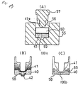
- Fig. 5 and 13 are for detailed explanation of the processes (K) - (N) of FIG. 4.
- FIG. 5(A) corresponds to the process (K) of FIG. 4.
- two stacked alloy layers with the PM alloy layer 51 for the head portion made of quenched powder aluminium alloy on the under side and the piston alloy layer 50 for the skirt portion made of the alloy comprising aluminium, silicon, copper, and magnesium on the under side, are place in a recess 56 of a preheated lower die 55 and pressed with a preheated upper die or punch 57 to forge-form in a piston shape.
- the symbol 100a indicates the interface between the two alloy layers before being forged, which is a flat surface in this embodiment.
- the two alloy layers are in contact with each other on the interface 100.
- Parting agent is applied on the cylindrical peripheral surface of the two alloy layers before forging.
- the shape of the punch 57 is determined to provide required thicknesses to the respective portions of the piston 58.
- a recess 59 is formed in the bottom center of the recess 56 of the lower die 55 to oppose a projection 57a of the punch 57.
- FIG. 5(B) corresponds to the process (L) of FIG. 4.
- the forged piston 58 has a projection 42 pushed out in the center of the head portion 40 corresponding to the recess 59 formed in the center of the lower die. 55.
- the periphery of the alloy layer 51 for the head portion rises while the thickness of the alloy layer 50 for the skirt portion below the projection 57a reduces and the periphery of the alloy layer 50 for the skirt portion rises farther.
- the interface 200 after forging presents a peripheral portion 200a rising higher beyond the pre-forging interface 100, a first dome portion 200b curving downward in a downwardly convex shape to a position lower than the pre-forging interface 100 along the projection 57a, and a second dome portion 200c curving farther downward in a downwardly convex shape in the center.
- the pre-forging flat interface 100 deforms into the post-forging interface 200. That is to say, since the area of the interface 100 is enlarged by the forging, not only the alloy layer 50 for the skirt portion but also the alloy layer 51 for the head portion extend largely on the interface. In this portion where the elongation is large, a large force is also exerted and oxide films are destroyed by forging.
- FIG. 5(C) corresponds to the process (N) of FIG. 4 in which various kinds of machining are carried out to for the piston.
- the projection 42 is machined off because the projection is not necessary after the hot forging. Piston ring grooves 65 are formed.
- the fiber flow formed in the process shown in FIG 5(B) remains.
- the position of the projection 42 is not limited in the center of the head portion 40.
- the shape of the projection 42 is not necessarily of an approximate truncated cone. Furthermore, two or more projections 42 may be provided.
- joining area is increased.
- the joining area may also be increased with a plural number of second domes 200c formed to correspond to the plural number of projections 42 to firmly join the alloy layer 51 for the head portion to the alloy layer 50 for the skirt portion.
- a recess may be formed on the top surface of the piston head.
- fiber flows are caused in the same manner as in the case of the projection described above to increase the joining strength.
- FIG. 6 shows examples of locations and shapes of the extruded projections described above.
- FIG. 6(A) shows an example in which a circularly extruded projection 42 is located in the center of the piston 58.
- the broken lines in the drawing show the positions of two main scavenging ports 60, 61, a sub-scavenging port 62, and an exhaust port 63 of a two-cycle engine.
- FIG. 6(B) shows an example in which the extruded projection 42 is displaced from the center of the piston 58 toward the exhaust port 63 to increase the strength on the exhaust side where temperature is high.
- a circularly extruded projection may be provided at a plural number of locations.
- FIG. 6(C) shows an example in which a circularly extruded projection 42 is disposed in the center and an annular projection 42' is disposed around the projection 42.
- FIG. 6(D) shows an example in which a curved, deformed, extruded projection 42" is disposed with a displacement from the center.
- FIG. 6(E) shows an example in which an annular projection 42' only is provided.
- a large number of stripes are radially formed around the extruded projections 42, 42', 42". These stripes represent fiber flows 64 radially extending from the extruded projections. As described before, these stripes are formed along the directions in which the textures move according to the slip of the alloy layers when they are forged and run generally at right angles to the contour of the extruded projection.
- the fiber flows are also formed on the interface between different materials.
- that the fiber flows are formed in at least one of the alloy layer 50 for the skirt portion and the alloy layer 51 for the head portion in the vicinity of the interface means that the elongation on the interface is large. Therefore, oxide films are destroyed on the interface, and the alloy layer 50 for the skirt portion and the alloy layer 51 for the head portion are firmly joined together by direct contact.
- the entire head portion including the piston ring groove is made of quenched powder aluminium alloy and the entire skirt portion is made of the alloy consisting of aluminium, silicon, copper, and magnesium.
- the constitution is not limited to the above but only part of the head portion may be constituted with the quenched powder aluminium alloy.
- FIG. 14(B) corresponds to the process (L) of FIG. 4.
- the forged piston 58 has a projection 42 pushed out in the center of the head portion 40 corresponding to the recess 59 formed in the center of the lower die 55.
- the interface 100a between the two alloy layers is deformed to be an interface 100b having a larger area.
- the deformation accompanied by the increase in the interface area causes relative slip between the two alloy layers on the head and skirt portion sides to destroy and remove oxide films on the interface, and is effective in providing a sufficient joining strength. In other words, if the central portion of the interface remains flat, the relative slip is less likely to occur and sufficient joining strength is not provided.
- the projection 42 is formed in the head center to cause relative slip by moving the forged materials up and down and to provide sufficient joining strength.
- fiber flows are caused to occur along the movement of the material textures at the time of forging in the vicinity of the projection 42 of the head portion 40 and a portion, corresponding to the projection 42, of the joining interface between the head and skirt portions.
- the fiber flows are caused by the relative slip between the two alloy layers of the head and skirt portions at the time of forging.
- the relative slip destroys the oxide films on the interface to provide sufficient joining strength.
- a fiber flow vertical to the top surface of the head portion 40 remains in the center surrounded with radial fiber flow lines.
- FIG. 13(C) corresponds to the process (N) of FIG. 4 in which various kinds of machining are carried out to for the piston.
- the projection 42 is machined off because the projection is not necessary after the hot forging. Piston ring grooves 65 are formed.
- the fiber flow formed in the process shown in FIG 5(B) remains.
- the position of the projection 42 is not limited in the center of the head portion 40.
- the shape of the projection 42 is not necessarily of an approximate truncated cone. Furthermore, two or more projections 42 may be provided.
- the finished piston 58 consists of the head portion entirely consisting of quenched powder aluminium alloy and the skirt portion entirely consisting of the alloy comprising aluminium, silicon, copper, and magnesium.
- the composition is not limited to the above but only part of the head portion may be made of quenched powder aluminium alloy.
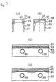
- FIG.7 is an explanatory drawing to show another composition distribution of quenched powder aluminium alloy for the piston head portion.
- FIG. 7(A) shows an example in which only the peripheral portion around the piston ring groove 65 of the head portion 40 is formed,with the quenched powder aluminium alloy (PM alloy).
- the peripheral portion of the head portion 40 where heat resistance is specially required is formed with the PM alloy having good heat resistance while other portions are formed with piston alloy having good forming property.
- ease of forge-forming is improved.
- the top land above the piston ring groove 65 may be made thinner. The thinner top land reduces the crevice volume and also the amount of unburned gas. and is effective as a measure for reducing exhaust emissions.
- FIG.7(C) is a peripherally extended view of the piston shown in FIG. 7(A).
- the quenched powder aluminium alloy layer 51 is formed in a uniform thickness over the periphery of the piston.
- FIG.7(B) shows an example in which the quenched powder aluminium alloy layer 51 is made thicker on the intake and exhaust sides while thinner on the piston pin boss sides.
- FIG. 7(D) is a peripherally extended view of the piston of (B).
- the thickness of the quenched powder aluminium alloy layer 51 is varied over the periphery so that its underside is generally wavy: at positions above the piston pin bosses 66, the thickness is reduced so that its underside is above the piston ring groove 65, while at positions above and between the piston pin bosses, the thickness is increased so that its underside is below the piston ring groove 65.
- the alloy layer 50 for the skirt portion and the alloy layer 51 for the head portion are firmly joined together through direct contact by arranging that the interface surface area is enlarged and the oxide films are destroyed after forging.
- fiber flows are formed along the elongation in the vicinity of the contact interface so as to increase strength against external forces working in the direction of bonding the fiber flows. That, is to say, when the piston is used in an actual engine and subjected to the gas pressure exerted on the head portion, the fiber flows radially extending toward the periphery support the pressure and transmit it to the piston pin bosses and protect the head portion.
- the following methods for enlarging the pre-forging contact interface area between the alloy layer 50 for the skirt portion and the alloy layer 51 for the head portion are farther the following methods for enlarging the pre-forging contact interface area between the alloy layer 50 for the skirt portion and the alloy layer 51 for the head portion.
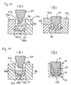
- FIG. 8 is a cross-sectional view to show another method of manufacturing the piston of the invention. Description of those symbols in FIG. 8 which are also used in FIG. 5 in common is omitted.
- On the underside of the alloy layer 51 for the head portion before forging is formed with a recess 51a.
- the projection 57a is moved down into the alloy layer 50 for the skirt portion until the recess 51a comes into contact with the lower die 55. This brings about the state shown in FIG. 8 (B) in which the central portion of the pre-forging interface 100 is deformed by forging to form the post-forging interface 200c.
- Other portions 200a, 200b of the post-forging interface are formed as described in reference to FIG. 5.
- the piston material before being processed has no extruded projection shown in FIG. 5 and so the processing is simple. If a pre-forging alloy layer 51 for the head portion is to be formed by sintering or the like, the recess 51a may be easily formed.
- FIG. 9 is a cross-sectional view to show still another method of manufacturing the piston of the invention. According to the method, the alloy layer 50 for the skirt portion and the alloy layer 51 for the head portion are firmly joined to the periphery of the piston.
- An annular recess 55a is formed on the bottom surface circumference of the recess 56 in the lower die 55.
- the periphery of the alloy layer 50 for the skirt portion rises. Along wit the rise, the periphery of the interface 100 also rises.
- the punch 57 is lowered farther, the rise of the periphery of the alloy layer 50 for the skirt portion is restricted or rather pushed back with the periphery 57b of the punch 57.
- the periphery of the alloy layer 51 for the head portion is pushed down through the alloy layer 50 for the skirt portion with the periphery 57b and forced into the recess 56.
- the interface periphery which has once risen lowers as shown in FIG. 9(B) to form a cone-like portion 200d. Since the interface periphery area also increases with forging, both alloy layers 50 and 51 are firmly joined together also on the cone-like portion 200d. Fiber flows are also formed in the alloy layers 50 and 51 in the vicinity of the interface 200. By the way, the extruded projection 51a is removed by a post-forging process.
- FIG. 10 is a cross-sectional view to show still another method of manufacturing the piston of the invention. This method is applicable to the piston 40 shown in FIG. 7 so that the alloy layer 50 for the skirt portion and the alloy layer 51 for the head portion are firmly joined to the periphery of the piston. Description of those symbols in FIG. 10 which are also used in FIG. 7(a) in common is omitted.
- the lower die 55 comprises a left die 55b and a right die 55c, respectively separable to left and right.
- a pre-forging alloy piece 51 for the head portion is of a hollow cylindrical shape.
- a projection 50a of the alloy piece 50 for the skirt portion fits into the hollow portion. Both alloy pieces come into contact with each other to form a planar interface 100a and a cylindrical interface 100b.
- a donut-shaped recess 55d is provided in the lower die 55 in the vicinity of the interface 100a. As shown in FIG. 10(B), both alloy materials 50 and 51 are squeezed out, and forced into the recess 55d to form a flange-like projection 90.
- the post-forging interface 200 enters the projection 90.
- the area of the interface 200 larger than the sum of the pre-forging areas of the interfaces 100a and 100b. Also, fiber flows are formed in both alloy materials 50 and 51 in the vicinity of the interface 200. The projection 90 is removed by a post-forging process.
- FIG. 11 is a cross-sectional view to show still another method of manufacturing the piston of the invention. This method is applicable to the piston 40 shown in FIG. 7 so that the alloy layer 50 for the skirt portion and the alloy layer 51 for the head portion are firmly joined to the periphery of the piston. Description of those symbols in FIG. 11 which are also used in FlGs. 5 and 10(a) in common is omitted.
- a donut-shaped recess 55a is formed in the peripheral portion of the bottom of the recess 56 of the lower die 55.
- both alloy materials 50 and 51 are squeezed out by forging and forced into the recess 55a to form a projection 91.
- the post-forging interface 200 enters the projection 91. That is to say, it is possible to make the area of the interface 200 larger than the sum of the pre-forging areas of the interfaces 100a and 100b. Also, fiber flows are formed in both alloy materials 50 and 51 in the vicinity of the interface 200.
- the projection 91 is removed by a post-forging process.
- FIG. 12 is a view of interface texture drawn in reference to a microscopic photograph of the joining interface of the piston of the invention.
- both alloy layers 50 and 51 are wavy on the interface S and extended into each other so that both textures are joined together.
- the wavy texture interface S formed on the joining interface in the piston by forge-joining of different materials according to the invention is formed by the elongation as well as relative slip when the different materials are press-joined with each other, and is confirmed by microscopic observation of the interface texture.
- the piston 58 of the above embodiment may be effectively used in engines operated at high speeds with high output in such vehicles as automobiles, motorcycles, snowmobiles, outboard motors, etc.
- composition of the alloys that can be used for the head portion and the skirt portion are as follows:
- alloys have been found advantageous for use as the alloy forming at least a portion of the skirt of the piston 20.
- These alloy embodiments are preferably manufactured by continuous casting or extrusion forming and then cut into the desired block, and may also be formed from powder metals, as described in more detail below.
- alloys contents which have been found suitable are as follows. These first three alloy embodiments are preferably manufactured by continuous casting or extrusion forming and then cut into the desired block.
- alloys are preferably made from powder metals:
Landscapes
- Engineering & Computer Science (AREA)
- General Engineering & Computer Science (AREA)
- Mechanical Engineering (AREA)
- Chemical & Material Sciences (AREA)
- Combustion & Propulsion (AREA)
- Composite Materials (AREA)
- Manufacturing & Machinery (AREA)
- Materials Engineering (AREA)
- Ocean & Marine Engineering (AREA)
- Pistons, Piston Rings, And Cylinders (AREA)
- Forging (AREA)
Claims (10)
- Verfahren zum Herstellen eines Kolbens (58) für einen Verbrennungsmotor, wobei der Kolben (58) einen Kopfabschnitt (40), der zu einer Brennkammer hin frei liegt, sowie einen Hemdabschnitt (41) umfasst, der in einem Zylinder gleitet, wobei es die folgenden Verfahrensschritte umfasst:Herstellen eines ersten Blocks aus einer ersten Legierung, die Al umfasst, zum Ausbilden des Kopfabschnitts (40);Herstellen eines zweiten Blocks aus einer zweiten Legierung, die Al umfasst, zum Ausbilden des Hemdabschnitts (41);Aufsetzen des zweiten Blocks auf den ersten Block, so dass die Blöcke an einer ersten Grenzfläche aneinander stoßen, die eine erste Fläche hat;Druckschmieden des ersten und des zweiten Blocks zu einem Kolben, um wenigstens einen Vorsprung (200b, 200c, 200f) an einer Verbindungs-Grenzfläche (100, 200) zwischen dem ersten und dem zweiten Block auszubilden und eine Grenzfläche auszubilden, die eine zweite Fläche hat, die größer ist als die erste Fläche, dadurch gekennzeichnet, dass damit auch wenigstens ein anderer Vorsprung (42, 51a, 90, 91) an einer Außenfläche des Kolbens (58) hergestellt wird.
- Verfahren nach Anspruch 1, wobei der erste und der zweite Block in einer Hauptvertiefung eines unteren Werkzeugs aufeinandergesetzt werden, und das des Weiteren den Schritt des Pressens eines oberen Werkzeugs in die Hauptvertiefung des unteren Werkzeugs und an die Blöcke umfasst.
- Verfahren nach Anspruch 2, wobei das untere Werkzeug eine Teilvertiefung aufweist, die sich von der Hauptvertiefung aus erstreckt, und das des Weiteren den Schritt des Verformens der ersten und/oder der zweiten Legierung in die Hauptvertiefung hinein zum Ausbilden eines Vorsprungs von dem Kolben einschließt.
- Verfahren nach einem der Ansprüche 1 bis 3, das des Weiteren den Schritt des Ausbildens des ersten Blocks aus einem Barren der ersten Legierung durch Schmelzen des Barrens, Härtungsverfestigen der geschmolzenen Legierung zu Pulver, Warm-Strangpressen des Pulvers zu einem Strangpressteil und Schneiden des Strangpressteils in Blöcke einer zweiten Legierung umfasst.
- Verfahren nach einem der Ansprüche 1 bis 4, das des Weiteren den Schritt des Spanens wenigstens einer Ringnut in den Kolben umfasst.
- Verfahren nach einem der Ansprüche 1 bis 5, das des Weiteren den Schritt des Wärmebehandelns des Kolbens nach dem Schmieden umfasst.
- Verfahren nach Anspruch 1, das die folgenden Schritte umfasst:Gewinnen eines verfestigten Teils der ersten Legierung;Gewinnen eines verfestigten Teils der zweiten Legierung; undDruckschmieden der Teile der ersten und der zweiten Legierung in eine Kolbenform, wobei der Schritt des Druckschmiedens des Weiteren den Schritt des Bewegens einer Fläche der ersten Legierung relativ zu einer Verbindungsfläche der zweiten Legierung umfasst.
- Verfahren nach Anspruch 7, wobei die Teile der ersten und der zweiten Legierung aufeinandergesetzt werden und an einer Grenzfläche aneinander stoßen, die eine erste Fläche hat, und beim Schmieden die erste sowie die zweite Legierung entlang einer Grenzfläche verbunden werden, die eine zweite Fläche hat, die größer ist als die erste Fläche.
- Verfahren nach Anspruch 7 oder 8, wobei während des Druckschmiedens eine Kornstruktur der ersten Legierung und eine Kornstruktur der zweiten Legierung wenigstens in dem Bereich, indem die erste und die zweite Legierung verbunden werden, in wenigstens einer Richtung verlängert werden.
- Verfahren nach einem der vorangehenden Ansprüche, das des Weiteren den Schritt des Entfernens des wenigstens einen anderen Vorsprungs (42, 50a, 90, 91) umfasst.
Applications Claiming Priority (6)
| Application Number | Priority Date | Filing Date | Title |
|---|---|---|---|
| JP12438696 | 1996-05-20 | ||
| JP12438696A JP3656970B2 (ja) | 1996-05-20 | 1996-05-20 | 内燃機関用ピストンおよびその製造方法 |
| JP124386/96 | 1996-05-20 | ||
| JP14270496 | 1996-06-05 | ||
| JP14270496 | 1996-06-05 | ||
| JP142704/96 | 1996-06-05 |
Publications (2)
| Publication Number | Publication Date |
|---|---|
| EP0809050A1 EP0809050A1 (de) | 1997-11-26 |
| EP0809050B1 true EP0809050B1 (de) | 2003-08-13 |
Family
ID=26461072
Family Applications (1)
| Application Number | Title | Priority Date | Filing Date |
|---|---|---|---|
| EP97108160A Expired - Lifetime EP0809050B1 (de) | 1996-05-20 | 1997-05-20 | Verfahren zur Herstellung einen Kolben für eine Brennkraftmaschine |
Country Status (3)
| Country | Link |
|---|---|
| US (2) | US5992015A (de) |
| EP (1) | EP0809050B1 (de) |
| DE (1) | DE69724035T2 (de) |
Cited By (1)
| Publication number | Priority date | Publication date | Assignee | Title |
|---|---|---|---|---|
| DE102007052499A1 (de) * | 2007-11-02 | 2009-05-07 | Mahle International Gmbh | Verfahren zur Herstellung eines Kolbens für einen Verbrennungsmotor sowie mit diesem Verfahren herstellbarer Kolben |
Families Citing this family (22)
| Publication number | Priority date | Publication date | Assignee | Title |
|---|---|---|---|---|
| EP0870919B1 (de) * | 1997-04-10 | 2003-03-05 | Yamaha Hatsudoki Kabushiki Kaisha | Brennkraftmaschinenkolben und Verfahren zu seiner Herstellung |
| JPH10288085A (ja) | 1997-04-10 | 1998-10-27 | Yamaha Motor Co Ltd | 内燃機関用ピストン |
| JPH1136030A (ja) * | 1997-07-17 | 1999-02-09 | Yamaha Motor Co Ltd | ピストン用アルミニウム合金及びピストン製造方法 |
| EP1127172A2 (de) * | 1997-12-19 | 2001-08-29 | Advanced Materials Lanxide, LLC | Metallmatrixverbundkörper dessen oberfläche erhöhte bearbeitbarkeit und verminderte abnutzung hat |
| US6266878B1 (en) * | 1999-02-02 | 2001-07-31 | Amcast Industrial Corporation | Process for producing variable displacement compressor pistons having hollow piston bodies and integral actuator rods |
| US6507999B1 (en) * | 1999-03-12 | 2003-01-21 | General Electric Company | Method of manufacturing internal combustion engine pistons |
| JP3928336B2 (ja) * | 1999-09-21 | 2007-06-13 | 株式会社豊田自動織機 | 圧縮機用ピストンの製造方法 |
| US6840155B2 (en) * | 2000-10-18 | 2005-01-11 | Federal-Mogul World Wide, Inc. | Multi-axially forged piston |
| US6487773B2 (en) * | 2001-03-23 | 2002-12-03 | Mahle Gmbh | Method of making one-piece piston |
| US6508162B2 (en) * | 2001-05-10 | 2003-01-21 | Federal-Mogul World Wide, Inc. | Dual alloy piston and method of manufacture |
| US6761852B2 (en) * | 2002-03-11 | 2004-07-13 | Advanced Materials Technologies Pte. Ltd. | Forming complex-shaped aluminum components |
| FR2842828B1 (fr) * | 2002-07-25 | 2005-04-29 | Snecma Moteurs | Piece mecanique, et procede de fabrication d'une telle piece mecanique |
| CN101694187A (zh) * | 2004-02-27 | 2010-04-14 | 雅马哈发动机株式会社 | 发动机部件及其制造方法 |
| DE102005003061B4 (de) * | 2005-01-22 | 2019-11-21 | Andreas Stihl Ag & Co. Kg | Kolben für einen Zweitaktmotor |
| DE602007000292D1 (de) * | 2006-07-13 | 2009-01-08 | Yamaha Motor Co Ltd | Geschmiedeter Kolben, Verbrennungsmotor, Transportvorrichtung und Verfahren zur Herstellung des geschmiedeten Kolbens |
| DE102006045729A1 (de) * | 2006-09-27 | 2008-04-03 | Mahle International Gmbh | Kolben für einen Verbrennungsmotor und Verfahren zu seiner Herstellung |
| DE102008058190A1 (de) * | 2008-11-20 | 2010-05-27 | Mahle International Gmbh | Zweiteiliger Kolben für einen Verbrennungsmotor |
| CN101966586B (zh) * | 2010-10-27 | 2012-02-01 | 河南科技大学 | 内燃机活塞毛坯制造方法 |
| DE102011078145A1 (de) * | 2011-06-27 | 2012-12-27 | Mahle International Gmbh | Schmiedeverfahren zur Herstellung eines Kolbens bzw. Kolbenschafts |
| DE102013219052A1 (de) * | 2013-09-23 | 2015-04-09 | Mahle International Gmbh | Kolben mit Kolbenringnut, insbesondere Kompressionsnut |
| US10711732B2 (en) | 2017-01-19 | 2020-07-14 | Industrial Parts Depot, Llc | Reduced height piston |
| CN111958191A (zh) * | 2020-09-02 | 2020-11-20 | 瑞安市创博机械有限公司 | 热涨式铝导辊加工生产工艺 |
Citations (5)
| Publication number | Priority date | Publication date | Assignee | Title |
|---|---|---|---|---|
| EP0035348A2 (de) * | 1980-02-27 | 1981-09-09 | The British Internal Combustion Engine Research Institute Limited | Gesinterte Formkörper aus Verbundwerkstoffen und ihre Herstellung |
| US4364159A (en) * | 1980-07-14 | 1982-12-21 | Trw Inc. | Method for manufacturing a forged piston with reinforced ring groove |
| JPS63132743A (ja) * | 1986-11-26 | 1988-06-04 | Suzuki Motor Co Ltd | ピストンの製造方法 |
| JPH01180927A (ja) * | 1988-01-13 | 1989-07-18 | Toyota Motor Corp | ピストン製造方法 |
| US4889557A (en) * | 1987-03-30 | 1989-12-26 | Toyota Jidosha Kabushiki Kaisha | Aluminium alloy having an excellent forgiability |
Family Cites Families (23)
| Publication number | Priority date | Publication date | Assignee | Title |
|---|---|---|---|---|
| US2074228A (en) * | 1935-03-25 | 1937-03-16 | Mahle Ernst | Light metal piston |
| DE4110023A1 (de) * | 1991-03-27 | 1992-10-01 | Ringsdorff Werke Gmbh | Stossdaempferkolben aus ungleichen, gefuegten teilen |
| US2795467A (en) * | 1953-07-03 | 1957-06-11 | Thompson Prod Inc | Aluminum-silicon alloy extruded pistons |
| US2707136A (en) * | 1954-02-17 | 1955-04-26 | Permold Co | Insert ring for pistons |
| FR1226350A (fr) * | 1958-06-09 | 1960-07-11 | Ind De L Aluminium Sa | Procédé de fabrication de corps composites formés d'aluminium et d'aluminium fritté |
| NL6505582A (de) * | 1965-04-30 | 1966-10-31 | ||
| CH499719A (de) * | 1968-11-06 | 1970-11-30 | Nova Werke Ferber & Wran | Verfahren zur Herstellung eines Kolbens für Verbrennungsmotoren und nach dem Verfahren hergestellter Kolben |
| AU536976B2 (en) * | 1980-09-10 | 1984-05-31 | Comalco Limited | Aluminium-silicon alloys |
| US4440069A (en) * | 1982-06-11 | 1984-04-03 | Standard Oil Corporation (Indiana) | Composite piston and process |
| DE3404903A1 (de) * | 1984-02-11 | 1985-08-14 | Mahle Gmbh, 7000 Stuttgart | Gegossener aluminiumkolben fuer verbrennungsmotoren mit oberflaechlich mechanisch verdichteten nabenbohrungen |
| DE3509103A1 (de) * | 1985-03-14 | 1986-09-18 | Kolbenschmidt AG, 7107 Neckarsulm | Kolben fuer brennkraftmaschinen |
| GB8622538D0 (en) * | 1986-09-18 | 1986-10-22 | Ae Plc | Pistons |
| JPS63126661A (ja) * | 1986-11-17 | 1988-05-30 | Suzuki Motor Co Ltd | ピストンの製造方法 |
| DE3719121A1 (de) * | 1987-06-06 | 1988-12-15 | Mahle Gmbh | Verfahren zur herstellung eines aluminiumkolbens mit faserverstaerkten bereichen fuer verbrennungsmotoren |
| GB8814916D0 (en) * | 1988-06-23 | 1988-07-27 | T & N Technology Ltd | Production of sealed cavity |
| DE3822031A1 (de) * | 1988-06-30 | 1990-01-04 | Kolbenschmidt Ag | Leichtmetallkolben fuer brennkraftmaschinen |
| JPH02107749A (ja) | 1988-10-17 | 1990-04-19 | Mitsui Petrochem Ind Ltd | 非晶質合金薄膜 |
| BR8805716A (pt) * | 1988-10-26 | 1990-06-12 | Metal Leve Sa | Processo de fabricacao de embolo articulado e embolo articulado |
| JPH02233858A (ja) * | 1989-03-07 | 1990-09-17 | Mazda Motor Corp | アルミニウム合金製鍛造ピストンの製造方法 |
| JPH0785818B2 (ja) * | 1990-01-26 | 1995-09-20 | いすゞ自動車株式会社 | 複合材製鍛造部品及びその製造方法 |
| BR9001916A (pt) * | 1990-04-20 | 1991-11-12 | Metal Leve Sa | Processo de obtencao de embolo refrigerado e embolo refrigerado |
| BR9004990A (pt) * | 1990-09-28 | 1992-03-31 | Metal Leve Sa | Processo de fabricacao de cabeca de embolo articulado e embolo articulado |
| JP3777206B2 (ja) * | 1995-09-18 | 2006-05-24 | 本田技研工業株式会社 | Al合金製構造部材の製造方法 |
-
1997
- 1997-05-20 EP EP97108160A patent/EP0809050B1/de not_active Expired - Lifetime
- 1997-05-20 DE DE69724035T patent/DE69724035T2/de not_active Expired - Fee Related
-
1998
- 1998-04-16 US US09/061,614 patent/US5992015A/en not_active Expired - Lifetime
-
1999
- 1999-10-26 US US09/428,056 patent/US6209446B1/en not_active Expired - Lifetime
Patent Citations (5)
| Publication number | Priority date | Publication date | Assignee | Title |
|---|---|---|---|---|
| EP0035348A2 (de) * | 1980-02-27 | 1981-09-09 | The British Internal Combustion Engine Research Institute Limited | Gesinterte Formkörper aus Verbundwerkstoffen und ihre Herstellung |
| US4364159A (en) * | 1980-07-14 | 1982-12-21 | Trw Inc. | Method for manufacturing a forged piston with reinforced ring groove |
| JPS63132743A (ja) * | 1986-11-26 | 1988-06-04 | Suzuki Motor Co Ltd | ピストンの製造方法 |
| US4889557A (en) * | 1987-03-30 | 1989-12-26 | Toyota Jidosha Kabushiki Kaisha | Aluminium alloy having an excellent forgiability |
| JPH01180927A (ja) * | 1988-01-13 | 1989-07-18 | Toyota Motor Corp | ピストン製造方法 |
Cited By (1)
| Publication number | Priority date | Publication date | Assignee | Title |
|---|---|---|---|---|
| DE102007052499A1 (de) * | 2007-11-02 | 2009-05-07 | Mahle International Gmbh | Verfahren zur Herstellung eines Kolbens für einen Verbrennungsmotor sowie mit diesem Verfahren herstellbarer Kolben |
Also Published As
| Publication number | Publication date |
|---|---|
| DE69724035D1 (de) | 2003-09-18 |
| US6209446B1 (en) | 2001-04-03 |
| US5992015A (en) | 1999-11-30 |
| DE69724035T2 (de) | 2004-02-19 |
| EP0809050A1 (de) | 1997-11-26 |
Similar Documents
| Publication | Publication Date | Title |
|---|---|---|
| EP0809050B1 (de) | Verfahren zur Herstellung einen Kolben für eine Brennkraftmaschine | |
| US4548126A (en) | Piston with local inorganic fiber reinforcement and method of making the same | |
| JPH09177604A (ja) | 内燃機関用鋳造金属ピストン | |
| MXPA03011124A (es) | Metodo de fabricacion de un piston para motor de explosion y piston asi obtenido. | |
| JP3705676B2 (ja) | 内燃機関用ピストンの製造方法 | |
| US5507258A (en) | Pistons for internal combustion engines | |
| US20080000444A1 (en) | Piston for an Internal Combustion Engine, Method for Producing Said Piston and Use of a Copper Alloy in the Production of a Piston | |
| JPH10288085A (ja) | 内燃機関用ピストン | |
| JPH1082345A (ja) | 内燃機関用ピストンおよびその製造方法 | |
| US5671710A (en) | Pistons for internal combustion engines and method of manufacturing same | |
| EP0870919B1 (de) | Brennkraftmaschinenkolben und Verfahren zu seiner Herstellung | |
| JP3897416B2 (ja) | 粉末アルミ合金製シリンダーライナ | |
| US20200070240A1 (en) | Light weight inserts for piston rings, methods of manufacturing thereof and articles comprising the same | |
| JP3656970B2 (ja) | 内燃機関用ピストンおよびその製造方法 | |
| JP3635473B2 (ja) | 内燃機関用ピストンおよびその製造方法 | |
| JP3635474B2 (ja) | 内燃機関用ピストン及びその製造方法 | |
| JPH10288086A (ja) | 内燃機関用ピストン | |
| JP2572889B2 (ja) | ディーゼルエンジン用ピストンの製造方法 | |
| JPH01230737A (ja) | 複合材料製部材及びその製造方法 | |
| JP2002130048A (ja) | 内燃機関用ピストン | |
| RU2239511C1 (ru) | Способ изготовления крупногабаритных поршней двигателей внутреннего сгорания | |
| JPH1144251A (ja) | 2サイクルエンジンのピストン | |
| JP2001107802A (ja) | 高温耐摩耗性および熱伝導性の優れた冷却空洞付きピストンリング複合耐摩環 | |
| JPH0121163Y2 (de) | ||
| JP3883656B2 (ja) | 耐摩環およびそれを装着したピストン |
Legal Events
| Date | Code | Title | Description |
|---|---|---|---|
| PUAI | Public reference made under article 153(3) epc to a published international application that has entered the european phase |
Free format text: ORIGINAL CODE: 0009012 |
|
| AK | Designated contracting states |
Kind code of ref document: A1 Designated state(s): DE FR IT |
|
| 17P | Request for examination filed |
Effective date: 19980120 |
|
| 17Q | First examination report despatched |
Effective date: 19991227 |
|
| GRAH | Despatch of communication of intention to grant a patent |
Free format text: ORIGINAL CODE: EPIDOS IGRA |
|
| RTI1 | Title (correction) |
Free format text: METHOD OF MAKING A PISTON FOR AN INTERNAL COMBUSTION ENGINE |
|
| RTI1 | Title (correction) |
Free format text: METHOD OF MAKING A PISTON FOR AN INTERNAL COMBUSTION ENGINE |
|
| GRAH | Despatch of communication of intention to grant a patent |
Free format text: ORIGINAL CODE: EPIDOS IGRA |
|
| GRAA | (expected) grant |
Free format text: ORIGINAL CODE: 0009210 |
|
| AK | Designated contracting states |
Designated state(s): DE FR IT |
|
| PG25 | Lapsed in a contracting state [announced via postgrant information from national office to epo] |
Ref country code: FR Free format text: LAPSE BECAUSE OF NON-PAYMENT OF DUE FEES Effective date: 20030813 |
|
| REF | Corresponds to: |
Ref document number: 69724035 Country of ref document: DE Date of ref document: 20030918 Kind code of ref document: P |
|
| PLBE | No opposition filed within time limit |
Free format text: ORIGINAL CODE: 0009261 |
|
| STAA | Information on the status of an ep patent application or granted ep patent |
Free format text: STATUS: NO OPPOSITION FILED WITHIN TIME LIMIT |
|
| 26N | No opposition filed |
Effective date: 20040514 |
|
| EN | Fr: translation not filed | ||
| PGFP | Annual fee paid to national office [announced via postgrant information from national office to epo] |
Ref country code: DE Payment date: 20080529 Year of fee payment: 12 |
|
| PGFP | Annual fee paid to national office [announced via postgrant information from national office to epo] |
Ref country code: IT Payment date: 20080530 Year of fee payment: 12 |
|
| PG25 | Lapsed in a contracting state [announced via postgrant information from national office to epo] |
Ref country code: DE Free format text: LAPSE BECAUSE OF NON-PAYMENT OF DUE FEES Effective date: 20091201 |
|
| PG25 | Lapsed in a contracting state [announced via postgrant information from national office to epo] |
Ref country code: IT Free format text: LAPSE BECAUSE OF NON-PAYMENT OF DUE FEES Effective date: 20090520 |