EP0808933A2 - Waschmaschine - Google Patents
Waschmaschine Download PDFInfo
- Publication number
- EP0808933A2 EP0808933A2 EP97303439A EP97303439A EP0808933A2 EP 0808933 A2 EP0808933 A2 EP 0808933A2 EP 97303439 A EP97303439 A EP 97303439A EP 97303439 A EP97303439 A EP 97303439A EP 0808933 A2 EP0808933 A2 EP 0808933A2
- Authority
- EP
- European Patent Office
- Prior art keywords
- tub
- washing machine
- machine according
- vibration
- external casing
- Prior art date
- Legal status (The legal status is an assumption and is not a legal conclusion. Google has not performed a legal analysis and makes no representation as to the accuracy of the status listed.)
- Withdrawn
Links
Images


Classifications
-
- D—TEXTILES; PAPER
- D06—TREATMENT OF TEXTILES OR THE LIKE; LAUNDERING; FLEXIBLE MATERIALS NOT OTHERWISE PROVIDED FOR
- D06F—LAUNDERING, DRYING, IRONING, PRESSING OR FOLDING TEXTILE ARTICLES
- D06F37/00—Details specific to washing machines covered by groups D06F21/00 - D06F25/00
- D06F37/20—Mountings, e.g. resilient mountings, for the rotary receptacle, motor, tub or casing; Preventing or damping vibrations
- D06F37/24—Mountings, e.g. resilient mountings, for the rotary receptacle, motor, tub or casing; Preventing or damping vibrations in machines with a receptacle rotating or oscillating about a vertical axis
-
- D—TEXTILES; PAPER
- D06—TREATMENT OF TEXTILES OR THE LIKE; LAUNDERING; FLEXIBLE MATERIALS NOT OTHERWISE PROVIDED FOR
- D06F—LAUNDERING, DRYING, IRONING, PRESSING OR FOLDING TEXTILE ARTICLES
- D06F37/00—Details specific to washing machines covered by groups D06F21/00 - D06F25/00
- D06F37/20—Mountings, e.g. resilient mountings, for the rotary receptacle, motor, tub or casing; Preventing or damping vibrations
Definitions
- the present invention relates to a washing machine comprising a housing, a support structure within the housing and a drum for receiving a load of laundry, rotatably mounted to the support structure, and means for suppressing vibration of the drum.
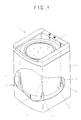
- a conventional washing machine 1 is illustrated in Figure 24 and includes an external casing 2 having a tub 3 and a spin basket 4 rotatably mounted therein.
- the tub 3 is suspended in the casing 2 by suspension bars via a suspension support 6.
- a pulsator 5 for forming a rotating water current for washing is provided at the bottom of the spin basket 4.
- a driving motor 7 and a shaft assembly 8 are installed beneath the tub 3, and selectively rotate the spin basket 4 or the pulsator 5 in a predetermined direction according to a preselected program to carry out an operation cycle of the washing machine.
- non-linear and irregular vibration of the spin basket 4 is transmitted to the tub 3 as it rotates. Severe vibration of the tub occurs during the spin cycle in which the rotational speed of the spin basket 4 is at its greatest.
- the degree of vibration is determined by the weight of the laundry and the degree of imbalance caused by an uneven distribution of the laundry in the spin basket. If the weight of the laundry is unevenly distributed, the spin basket 4 tends to wobble and collide with the tub 3 as it rotates causing increased vibration and excessive noise.
- a conventional washing machine 1 includes a suspension support 6 having a suspension bar and a friction buffer 6' provided at one end fixed to the tub 3.
- the friction buffer 6' includes a bell shaped friction cover and a friction member having a resilient spring provided therein to attenuate vibration transferred to the tub 3.
- a particular disadvantage with the arrangement discussed above is that when the spin basket contains more than a prescribed capacity of laundry, the suspension support 6 cannot adequately attenuate the vibration as the suspension support 6 is mounted initially according to the weighing centre at a no-load state in the tub. Further, because of its structure, the suspension support 6 can only attenuate vibration in an up-and-down direction. Therefore, if the spin basket 4 rotates in a left-and-right direction due to the uneven distribution of laundry in the spin basket, such left-and-right vibration is transferred to the tub 3 without being attenuated. As a result, the tub 3 wobbles and prevents the washing machine from operating smoothly. When the wobble is severe, excessive noise is generated due to contact between the tub 3 and the external casing 2.
- a washing machine having a system for attenuating the irregular and non-linear vibration of the spin basket 4 has been recently proposed in US patent No. 5,269,159.
- a mutual repelling force between the tub 3 and the casing 2 is induced between opposing electromagnets, mounted on the outer surface of the tub 3 and inner surface of the casing 2 while a mutual attraction force is induced therebetween in a contrary situation, to thereby maintain a constant distance between the tub 3 and the external casing 2.
- a particular disadvantage with the aforementioned conventional washing machine is that it includes a complicated circuit structure resulting a high cost. Further, it does not operate sufficiently to attenuate the vibration of the spin basket 4. Even when used in a washing machine having an additional damper the structure is complicated and the left-and-right vibration of the tub 3 generated by the rotational movement of the spin basket 4 cannot be efficiently attenuated.
- a washing machine is characterised in that the means for suppressing vibration includes a bearing between the support structure and the housing below the drum, the bearing having first and second bearing surfaces arranged to frictionally engage one another so as to suppress vibration of the drum.
- contact surfaces on the first and second members engage when the load in the drum reaches said predetermined weight.
- the contact surfaces are formed from a material having a high coefficient of friction.
- one of the first or second members is moveable against a spring bias in a direction substantially parallel to an axis of rotation of the drum when engaged by the other member.
- the first member and the second member may have a plane-shaped frictional contact surface or a curved-shaped frictional contact surface, respectively.
- a throughhole is formed in the centre area of the first member in the axial direction of the tub.
- the relative movement means can alternatively be simply constructed as a telescopic bar whose one end is fixed to the tub and other end is fixed to the first member, to be extendable and contractable along the axial direction of the tub.
- the washing machine further comprises a relative movement means for enabling the second member to move relatively along the axial direction of the tub with respect to the bottom surface of the external casing.
- the above relative movement means can be simply constructed using a spring member for elastically urging the second member toward the first member which is interposed between the second member and the bottom surface of the external casing.
- the washing machine further comprises a third member which is disposed to oppose the second member so that the first member is interposed therebetween to frictionally contact the first member.
- the washing machine further comprises an elastically pressing means for elastically pressing the second and third members with respect to the first member.
- the first member extends along the axial direction of the tub in the form of a bar
- the second member has an accommodation hole for accommodating the first member.
- a modified damping unit can be provided so that an elastic attenuation member which contacts the first member to be elastically deformed is attached in the inner surface of the accommodation hole.
- spin basket is an example of a "drum” referred to in the claims.
- washing machine should be taken to include tumble dryers, spin dryers and the like.
- a washing machine 1 having a damper 11 includes a generally rectangular external casing 2 having a generally cylindrical tub 3 and spin basket 4 accommodated therein as in the conventional washing machine of Figure 24.
- a washing machine 1 having a damper 11 includes a generally rectangular external casing 2 having a generally cylindrical tub 3 and spin basket 4 accommodated therein as in the conventional washing machine of Figure 24.
- the same labels and reference numerals are used for the same elements.
- a plurality of holes are provided in the spin basket 4 to allow water to pass to and from the tub 3.
- a pulsator 5 for forming a rotational flow of water for washing the laundry is provided on the bottom of the spin basket 4.
- the tub 3 is supported by the external casing by suspension supports 6.
- a power transmission unit 9 including a driving motor 7 and a shaft assembly 8 is installed in a lower side of the washing machine.
- the shaft assembly 8 is surrounded by a housing 10 and is mounted on the underside of the tub 3.
- the power transmission unit 9 rotates the spin basket 4 or the pulsator 5 in the forward or reverse direction according to a persecuted washing cycle program.
- a damper 11 is mounted on the lower side of the housing 10 and the bottom of the external casing 2.
- the damper 11 includes a first member 13 which is mounted on the lower surface of the housing 10, a second member 15 opposite the first member 13, and a spring member 17 for elastically supporting the second member 15 on the bottom of the external casing 2.
- the first member 13 and the second member 15 are formed of a plate-shaped body, respectively.
- the mutual contact surface of the first and second members 13 and 15 is a partial spherical surface.
- the spring member 17 is a compression coil spring and urges the second member 15 upwards with respect to the tub 3 in an axial direction of the tub 3, to thereby elastically support the first member 13.
- the first and second members 13 and 15 are made of a material which can endure frictional contact.
- a material can be any one selected from a group consisting of rubber, polyamid, polyacetyle and polypropylene.
- the first and second members 13 and 15 are formed of a steel plate and one of the above materials is interposed between the frictional contact surfaces.
- the first member 13 mounted on the lower side of the tub 3 comes into contact with the second member 15. Further increase in the weight of the tub 3 causes the first member 13 to press against the second member 15 against the force of the spring member 17 which urges the tub 3 upwards.
- vibration transferred to the tub 3 is primarily attenuated by the suspension support 6 and the irregular and non-linear vibration causing the tub 3 to wobble is suppressed by the frictional contact between the first and second members 13 and 15. As a result, noise and wear of the washing machine induced by the vibration of the tub 3 is reduced.
- damper applied to the washing machine according to the present invention can take various forms and modifications or variations of the first embodiment will now be described using the same reference numerals and labels assigned with respect to the same elements as those of the first embodiment in Figures 1 and 2.
- a damper 21 includes a first member 13 which is installed under the lower side of the tub 3, a second member 15 which is disposed opposed to the first member 13, and spring members 17 for elastically urging the second member 15 upwardly with respect to the tub 3 along the axial direction of the tub 3.
- the first member 13 is mounted on the free end of a connecting bar 19 which extends downwardly from the bottom of the housing 10, and the second member 15 is installed on a support plate 20 which is disposed on the bottom of the external casing 2.
- the spring members 17, that is, compression coil springs are mounted between a support plate 20 and the second member 15.
- the first and second members 13 and 15 are plate shaped and a plurality of frictional pieces 43 are interposed between the first and second members 13 and 15. These frictional pieces 43 can be formed of a semi-sphere or a plate-shaped body, respectively.
- the frictional pieces 43 enable the first member 13 to move with respect to the second member 15 in correspondence to the vibration of the tub 3.
- the vibration of the tub 3 is attenuated by the contact frictional force of the both members 13 and 15 and the problems caused by the vibration are overcome.
- the frictional contact forces of the first and second members 13 and 15 is increased by the frictional pieces 43 interposed between the members 13 and 15, to thereby more effectively attenuate the vibration of the tub 3.
- a first member 13 is mounted for axial movement along a connecting bar 19 extending downwardly from the lower surface of the housing 10 and a fixing ring 33 prevents detachment of the first member 13 from the connecting bar 19.
- Second members 15 are mounted on the bottom of the external casing 2 opposite the first member 13 and a spring member 17 in the form of a compression spring, for elastically urging the first member 13 downwards is interposed on the connecting bar 19 between the first member 13 and the housing 10.
- a frictional material 18 is interposed between the first and second members 13 and 15.
- the damper 31 attenuates vibration due to the irregular and non-linear up-and-down movement transferred to the tub 3 through the frictional contact of the first and second members 13 and 15.
- the spring member 17 elastically urges the first member 13 downwardly into contact with the second member 15.
- a damper 41 according to a fourth embodiment includes a first member 13 which is slidably connected to the lower portion of the tub 3, on the side surface of the housing 10, a second member 15 which has a partial spherical upper surface in correspondence with a concave surface on the first member 13, and spring members 17 for elastically urging the first member 13 downwards against the second member 15 to its initial state.
- Hemispherically shaped frictional pieces 43 are interposed between the housing 10 and the first member 13 and have a concave surface corresponding to a convex surface of the second member 15. The first member 13 can slidably move along the housing 10.
- a plurality of hemispherical shaped frictional pieces 43 are interposed between the contact surfaces of the first and second members 13 and 15, that is, the concave and convex surfaces thereof and between the second member 15 and the bottom of the external casing 2.
- the spring members 17 are formed of a pulling coil spring whose one end is fixed to the side edge of the first member 13 and other end is fixed to the bottom of the external casing 2.
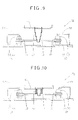
- Figures 6 and 7 show the operational states of the damper according to the fourth embodiment of Figure 5.
- the damper 41 suppresses the wobble via the frictional movement of first and second members 13 and 15 and the restoring force of spring members 17. That is, if the tub 3 inclines in one direction, for example, to the left, the first member 13 moves relative to the second member 15 and the spring member 17 which is disposed on the right side (as shown in Figure 7) of the first member 13 is pulled. The tub is then restored into its initial state by the restoring force of the pulled spring member 17.
- FIG 8 illustrates a transverse sectional view of a washing machine having a damper according to a fifth embodiment of the present invention
- Figures 9 and 10 are enlarged views showing an operating state of the damper according to the fifth embodiment of Figure 8.
- a damper 51 includes a first member 13 to receive the vibration of the tub 3 sandwiched between second members 15 at either edge of the first member 13.
- a throughhole is formed in the central area of the first member 13 and the distal end of a telescopic bar 57 extending from the lower surface of the housing 10 passes through the hole in the first member 13 and is attached thereto.
- the second member 15 includes an upper frictional plate which contacts the upper surfaces of the first member 13 and a lower frictional plate which contacts the lower surface thereof.
- the second members 15 on the upper surface of the first member 13 are fixed on supports 59 extending from the bottom of the external casing 2. Frictional materials 18 are interposed in the contact surfaces between the first member 13 and the upper and lower frictional plates 53 and 55.
- FIGS 11 and 12 are an enlarged transverse sectional view of washing machines having dampers according to sixth and seventh embodiments of the present invention, respectively.
- a damper 61 of a washing machine 1 according to a sixth embodiment is shown in Figure 11 and has a first member 13 mounted on the distal end of a connecting bar 19 extending downwardly from the lower surface of the housing 10.
- a second member 15 is mounted on the bottom of the external casing 2.
- a fixing damper 63 is mounted on the upper surface of the second member 15 and accommodates the first member 13.
- the fixing damper 63 is provided with a hole 65 through which the connecting bar 19 passes and sufficient clearance is provided between the connecting bar 19 and the fixing damper 63 to enable the connecting bar 19 to move laterally within the hole 65.
- the vibration transferred to the connecting bar 19 from the tub 3 is limited by the throughhole 65.
- the upper and lower surfaces of the first member 13 are in frictional contact with the lower surface of the fixing damper 63 and the upper surface of the second member 15, respectively.
- Spring members 17 are interposed between the second member 15 and the bottom of the external casing 2, to variably and elastically support the relative position of the second member 15 due to vibration of the tub 3 in a vertical direction.
- vibration of the tub 3 in a horizontal direction is attenuated by frictional resistance resulting from contact between the first member 13 and the second member 15 and between the first member 13 and the fixing damper 63, respectively and vibration of the tub 3 in a vertical direction is attenuated by the second member 15 which is variably and elastically supported via the spring members 17.
- a damper 17 according to a seventh embodiment is shown in Figure 12 and has a support plate 20 which is fixed on the bottom of the external casing (not shown).
- a second member 15 is bolted at 77 to the support plate 20.
- a fixing damper 63 having a throughhole 65 in the centre is provided on the upper surface of the second member 15.
- the first member 13 is accommodated in the fixing damper 63 so that it can move laterally therein and a connecting bar 19 extends upwardly from the central area of the upper surface of the first member 13 and passes through the hole 65 in the fixing damper 63.
- a damping tube 75 extends downwardly from the housing 10 and connecting bar 19 is accommodated therein so that it can move in a vertical direction.
- a spring member 17 is interposed between the connecting bar 19 and the bottom of the housing 10 in the damping tube 75.
- the spring member 17 elastically urges the first member 13 downwardly with respect to the tube 3 along the axial direction of the tub 3 so that the vibration of the tub in a vertical direction is attenuated by the spring member 17.
- vibration of the tub in the horizontal direction is attenuated by the mutual frictional contact between the first member 13, and the second member 15 and between the first member and the fixing damper 63.
- FIG. 13 is a transverse sectional view of a washing machine having a damper according to an eighth embodiment of the present invention and Figure 14 is an enlarged view of the damper according to the eighth embodiment of Figure 13.
- the damper 81 includes a bar 83 which extends downwardly from the underside of the housing 10.
- a first member 13 having a damping hole 84 of a diameter greater than that of the diameter bar 83 is sandwiched between a second member 15 and a third member 85.
- the third member 85 includes a damping upper plate 87 and a damping lower plate 89 which are respectively installed on the upper portions of the first member 13 and the lower portion of the second member 15.
- the damping upper and lower plates 87 and 89 are bolted together via connection 77.
- the second and third members 15 and 85 have a damping hole 86 of a diameter greater than that of the damping hole 84 formed on the first member 13, respectively.
- the edges of the damping lower plate 89 extend laterally and are fixed on the left and right inner wall surfaces of the external casing 2.
- the acting bar 83 extending downwardly from the housing 10 penetrates the throughhole 84 and 96 of the frictional members 13, 15 and 85.
- vertical and horizontal movement of the bar 83 caused by vibration of the tub 3 is attenuated due to the contact between the lower surface of the damping upper plate 87 and the upper surface of the second member 15.
- a frictional material 18 can be interposed between the first member 13 and each contact surface.
- FIG 15 is a transverse sectional view of washing machine having a damper according to a ninth embodiment of the present invention and Figure 16 is an enlarged exploded perspective view of the damper according to the ninth embodiment of Figure 15.
- a damper 91 has a bar 83 which extends downwardly from the underside of the lower surface of the housing 10 and includes a first member 13 having a damping hole 84 of a diameter greater than the diameter of the bar 83 sandwiched between a second member 15 and a third member 85.
- the second and third members 15 and 85 have a damping hole 86 having a larger diameter than that of the damping hole 84 formed on the first member 13, respectively.
- the second and third members 15 and 85 are loosely connected with each other by a bolt 97 and a nut 99 along their circumference.
- a spring member 17 is interposed between the second member 15 and the head of the bolt 77 and urges the second member 15 toward the first member 13 to maintain a consistent connecting force between the frictional members 13, 15 and 85 which are held together by the bolt 77.
- a hollow rib 93 extends upwardly from the bottom of the external casing 2 and has a hook accommodation hole (not shown) formed on its upper portion for attachment to a corresponding hook 95 formed on the lower surface of the second member 15.
- the mutually combined frictional members 13, 15 and 85 can be disposed in a predetermined position on the bottom of the external casing 2 by the hook 95 and the hook accommodation hole.
- the bar 83 extends through the damping holes 84 and 86 in the frictional members 13, 15 and 85.
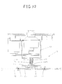
- FIGs 17 and 18 illustrate a transverse sectional view of a washing machine having a damper according to tenth and eleventh embodiments of the present invention, respectively.
- dampers having the same structure as that of ninth embodiment of Figures 15 and 16 are employed.
- a plurality of dampers 91 are symmetrically mounted parallel to the longitudinal axis of the tub 3.
- the support structure of a damper 101 according to the ninth embodiment is modified.
- both edges 103 of a third member 95 extend laterally and are fixed on the side wall surface of the external casing 2.
- the frictional members 13, 15 and 85 are disposed at a predetermined interval on the bottom of the external casing 2.
- the dampers 91 and 101 having the above described structure provide the same vibration attenuation effect as in the previous embodiments.
- FIG 20 is a transverse sectional view of a washing machine having a damper according to a twelfth embodiment of the present invention and Figure 21 is an enlarged perspective exploded view of the damper according to the twelfth embodiment of Figure 20.
- a damper 111 according to this embodiment has a structure slightly different from those of Figures 15 to 19. As can be seen from the drawings, a mounting rib 113 which extends from both edges of the second member 15 is provided, through which the damper 111 is fixed to the bottom of an external casing 2.
- a plurality of frictional contacts 115 and 117 on each plate surface are provided at predetermined positions on the first and second members 13 and 15. These frictional contacts 115 and 117 cause frictional members to be separated from each other by a small distance. Accordingly, a foreign substance such as water which gets into the damper 111 flows out between the frictional members which maintains a contact frictional coefficient between the members 13, 15.
- FIG 22 is a transverse sectional view of a washing machine having a damper according to a thirteenth embodiment of the present invention.
- the washing machine 1 shown in Figure 22 has a slightly different construction from those of the previous embodiments.
- a damper 121 includes first members 13 which extend downwardly from the underside of the tub 3 and second members 15 which are mounted on the base of the external casing 2 each have hole 123 having a greater diameter than the diameter of the first member 13 for accommodating the end of the first members 13.
- An elastic attenuation member 125 which is elastically deformed on contact by the first member 13 is attached to the inner surface second member 15 through which each hole 123 is formed. It is preferable that the elastic attenuation member 125 is formed of a vibration-proof material having a weak restoring force and a buffering capacity, such as a sponge material.
- vibration of the tub 3 during rotation of the spin basket 4 is transmitted to the first members 13.
- the first members 13 are accommodated in the accommodation hole in the second member 15, the movement of the first members, and therefore the tub, is limited. Vibration of the tub 3 is accordingly attenuated.
- At least one pair of dampers having the above construction can be provided on the bottom of the external casing 2, which doubles the above effect.
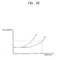
- Figure 23 is a characteristic graph showing the relationship between displacement of the tub 3 and unbalance of a load in a conventional tub 3 (curve A) and a tub in which a damper 11, 21, 31, 41, 51, 61, 71, 81, 91, 101, 111 or 121 according to the preferred embodiments of the present invention is installed (curve B).
- the washing machine 1 having the damper 11, 21, 31, 41, 51, 61, 71, 81, 91, 101, 111 or 121 substantially reduces the vibration of the tub 3 generated by the rotation of the spin basket 4 during a washing cycle, particularly during the spin cycle, compared with the conventional washing machine.
- the washing machine 1 having a damper according to the present invention is not limited in the above described embodiments, and can be embodied by various modifications within the scope of the appended claims.
- the washing machine having a damper according to the present invention effectively attenuates vibration generated during washing, rinsing and spin cycles which is proportional to the amount of laundry in the spin basket.
- the linear vibration of the tub due to imbalance of laundry less than a predetermined weight is attenuated by a suspension support as in the conventional art.
- the vibration of the tub when an excessive amount of laundry washes is input primarily attenuated by the above suspension support and is secondarily attenuated by a mutual frictional contact between the first and second members via the damper according to the above described embodiments.
Landscapes
- Engineering & Computer Science (AREA)
- Textile Engineering (AREA)
- Main Body Construction Of Washing Machines And Laundry Dryers (AREA)
- Accessory Of Washing/Drying Machine, Commercial Washing/Drying Machine, Other Washing/Drying Machine (AREA)
- Vibration Prevention Devices (AREA)
Applications Claiming Priority (20)
| Application Number | Priority Date | Filing Date | Title |
|---|---|---|---|
| KR9612817 | 1996-05-21 | ||
| KR2019960012817U KR0136467Y1 (ko) | 1996-05-21 | 1996-05-21 | 세탁조의 진동감쇠용 댐핑장치를 갖는 세탁기 |
| KR9613135 | 1996-05-23 | ||
| KR9613138 | 1996-05-23 | ||
| KR2019960013135U KR0136451Y1 (ko) | 1996-05-23 | 1996-05-23 | 세탁기의 세탁조 진동감쇠장치 |
| KR2019960013138U KR0136468Y1 (ko) | 1996-05-23 | 1996-05-23 | 세탁기의 세탁조 진동 감쇠용 댐핑장치 |
| KR9613178 | 1996-05-25 | ||
| KR2019960013178U KR0136459Y1 (ko) | 1996-05-25 | 1996-05-25 | 세탁조 진동감쇠용 댐핑장치를 갖는 세탁기 |
| KR2019960013459U KR0128749Y1 (ko) | 1996-05-28 | 1996-05-28 | 자동세탁기의 진동방지장치 |
| KR9613459 | 1996-05-28 | ||
| KR9613719 | 1996-05-29 | ||
| KR9613683 | 1996-05-29 | ||
| KR2019960013719U KR200142967Y1 (ko) | 1996-05-29 | 1996-05-29 | 세탁조의 진동감쇠용 댐핑장치를 갖는 세탁기 |
| KR9613717 | 1996-05-29 | ||
| KR2019960013683U KR970062430U (ko) | 1996-05-29 | 1996-05-29 | 자동세탁기의 진동방지장치 |
| KR2019960013717U KR0136445Y1 (ko) | 1996-05-29 | 1996-05-29 | 세탁조의 진동감쇠용 댐핑장치를 갖는 세탁기 |
| KR9613940 | 1996-05-30 | ||
| KR2019960013940U KR0138907Y1 (ko) | 1996-05-30 | 1996-05-30 | 자동세탁기의 진동감소장치 |
| KR9632523 | 1996-10-01 | ||
| KR2019960032523U KR200142469Y1 (ko) | 1996-10-01 | 1996-10-01 | 세탁기 |
Publications (2)
| Publication Number | Publication Date |
|---|---|
| EP0808933A2 true EP0808933A2 (de) | 1997-11-26 |
| EP0808933A3 EP0808933A3 (de) | 1998-05-27 |
Family
ID=27580562
Family Applications (1)
| Application Number | Title | Priority Date | Filing Date |
|---|---|---|---|
| EP97303439A Withdrawn EP0808933A3 (de) | 1996-05-21 | 1997-05-20 | Waschmaschine |
Country Status (5)
| Country | Link |
|---|---|
| US (1) | US5946947A (de) |
| EP (1) | EP0808933A3 (de) |
| JP (1) | JP2991671B2 (de) |
| CN (1) | CN1085270C (de) |
| BR (1) | BR9703303A (de) |
Cited By (5)
| Publication number | Priority date | Publication date | Assignee | Title |
|---|---|---|---|---|
| EP2700743A3 (de) * | 2012-08-23 | 2014-03-05 | LG Electronics Inc. | Zusätzliche Waschmaschine und Gewebebehandlungsvorrichtung damit |
| JP2015066060A (ja) * | 2013-09-27 | 2015-04-13 | 株式会社東芝 | 洗濯機 |
| US9670609B2 (en) | 2013-01-16 | 2017-06-06 | Lg Electronics Inc. | Auxiliary washing machine and laundry treatment apparatus using the same |
| CN107675434A (zh) * | 2017-10-24 | 2018-02-09 | 青岛海尔洗衣机有限公司 | 减振支撑装置及洗衣机 |
| US10202719B2 (en) | 2016-03-17 | 2019-02-12 | Whirlpool Corporation | Laundry treating appliance with tub having a flexible portion |
Families Citing this family (29)
| Publication number | Priority date | Publication date | Assignee | Title |
|---|---|---|---|---|
| KR100436555B1 (ko) * | 2001-09-19 | 2004-06-16 | 엘지전자 주식회사 | 부력 클러치가 구비된 세탁기 |
| KR100474913B1 (ko) * | 2002-08-09 | 2005-03-10 | 엘지전자 주식회사 | 드럼세탁기용 방진구조체 |
| KR100471456B1 (ko) * | 2003-03-26 | 2005-03-10 | 엘지전자 주식회사 | 드럼세탁기의 댐퍼 지지구조 |
| KR101052787B1 (ko) * | 2003-11-18 | 2011-07-29 | 삼성전자주식회사 | 세탁기 및 그 제어 방법 |
| US7290414B2 (en) * | 2004-03-26 | 2007-11-06 | Freudenberg-Nok General Partnership | Integrated laundry suspension system |
| KR101084117B1 (ko) * | 2004-06-01 | 2011-11-18 | 엘지전자 주식회사 | 드럼세탁기의 베이스구조 |
| US7454928B2 (en) * | 2004-08-09 | 2008-11-25 | Freudenberg-Nok General Partnership | Multi-component isolation damping system for a laundry washing machine |
| KR20060064311A (ko) * | 2004-12-08 | 2006-06-13 | 삼성전자주식회사 | 동흡진기를 구비하는 세탁기 |
| KR100637668B1 (ko) * | 2005-09-01 | 2006-10-24 | 삼성전자주식회사 | 세탁기 |
| JP4589893B2 (ja) * | 2006-05-30 | 2010-12-01 | シャープ株式会社 | 洗濯機 |
| KR20130052071A (ko) * | 2011-11-11 | 2013-05-22 | 삼성전자주식회사 | 드럼 세탁기 |
| KR20130116633A (ko) * | 2012-04-16 | 2013-10-24 | 삼성전자주식회사 | 뎀핑장치를 구비하는 세탁기 |
| KR20150017889A (ko) * | 2013-08-08 | 2015-02-23 | 삼성전자주식회사 | 세탁기 포장용 하부 완충장치 |
| KR20150075835A (ko) * | 2013-12-26 | 2015-07-06 | 동부대우전자 주식회사 | 세탁기의 진동감쇄장치 |
| EP3017738B1 (de) * | 2014-11-06 | 2018-10-31 | Vorwerk & Co. Interholding GmbH | Standfuss eines gerätes, insbesondere einer tisch-küchenmaschine |
| KR102315657B1 (ko) * | 2015-03-16 | 2021-10-20 | 엘지전자 주식회사 | 세탁물 처리기기 |
| US11035065B2 (en) * | 2015-03-16 | 2021-06-15 | Lg Electronics Inc. | Laundry processing apparatus |
| WO2017141260A1 (en) * | 2016-02-15 | 2017-08-24 | Wilson Varghese | Automatic washing machine which simultaneously agitates, squeezes and spins water soaked clothes to wash and dehydrate |
| EP3266921B1 (de) | 2016-07-07 | 2019-09-04 | LG Electronics Inc. | Wäschebehandlungsvorrichtung |
| EP3266920B1 (de) | 2016-07-07 | 2020-09-30 | LG Electronics Inc. -1- | Wäschebehandlungsvorrichtung |
| JP6740445B2 (ja) | 2016-07-07 | 2020-08-12 | エルジー エレクトロニクス インコーポレイティド | 洗濯物処理装置 |
| CN107587313B (zh) | 2016-07-07 | 2020-08-21 | Lg电子株式会社 | 洗涤物处理装置 |
| CN108729125B (zh) * | 2017-04-24 | 2020-09-25 | 青岛胶南海尔洗衣机有限公司 | 一种洗衣机 |
| CN109423826B (zh) * | 2017-08-28 | 2022-03-15 | 青岛海尔洗衣机有限公司 | 用于衣物处理设备的减振装置和衣物处理设备 |
| CN109423827B (zh) * | 2017-08-28 | 2022-04-08 | 重庆海尔洗衣机有限公司 | 用于衣物处理设备的减振装置和衣物处理设备 |
| CN111020962A (zh) * | 2018-02-12 | 2020-04-17 | 青岛海尔洗衣机有限公司 | 一种波轮洗衣机 |
| CN113897766A (zh) * | 2020-06-22 | 2022-01-07 | 青岛海尔洗衣机有限公司 | 波轮洗衣机 |
| CN113106705B (zh) * | 2021-04-22 | 2023-01-03 | 南京创阳电子有限公司 | 一种降噪系统及其降噪洗衣机 |
| KR20230020731A (ko) * | 2021-08-04 | 2023-02-13 | 삼성전자주식회사 | 세탁기 |
Family Cites Families (13)
| Publication number | Priority date | Publication date | Assignee | Title |
|---|---|---|---|---|
| FR1159456A (fr) * | 1955-11-01 | 1958-06-27 | Kelvin & Hughes Ltd | Dispositif sensible à la lumière pour mesurer un degré d'opacité |
| US3026700A (en) * | 1960-10-17 | 1962-03-27 | Gen Electric | Clothes washing machine having a suspension system which serves as a liquid seal |
| US3132098A (en) * | 1962-02-28 | 1964-05-05 | Gen Electric | Centrifuging machine having antiprecessional damping means |
| US3268082A (en) * | 1963-05-31 | 1966-08-23 | Gen Motors Corp | Domestic appliance |
| US3269544A (en) * | 1963-08-30 | 1966-08-30 | Gen Motors Corp | Domestic appliance |
| US3247689A (en) * | 1964-05-07 | 1966-04-26 | Westinghouse Electric Corp | Tub unit and suspension basic structure for agitator washer |
| GB1077489A (en) * | 1964-09-16 | 1967-07-26 | Westinghouse Electric Corp | Washing machine |
| US3476253A (en) * | 1965-02-04 | 1969-11-04 | Gen Motors Corp | Washing machine support assembly |
| US3952557A (en) * | 1974-06-20 | 1976-04-27 | General Electric Company | Wobble washing machine |
| US3922892A (en) * | 1974-07-01 | 1975-12-02 | Joseph Leib | Cleaning machine utilizing non-liquid cleaning agents |
| US4403484A (en) * | 1981-09-28 | 1983-09-13 | General Electric Company | Dual node support assembly for washing machine |
| US4475363A (en) * | 1983-06-06 | 1984-10-09 | General Electric Company | Adjustable dual node support assembly for washing machine |
| KR930010163B1 (ko) * | 1991-01-26 | 1993-10-15 | 삼성전자 주식회사 | 세탁기의 진동제어장치 |
-
1997
- 1997-05-14 US US08/856,086 patent/US5946947A/en not_active Expired - Fee Related
- 1997-05-16 JP JP12751897A patent/JP2991671B2/ja not_active Expired - Fee Related
- 1997-05-20 CN CN97104297A patent/CN1085270C/zh not_active Expired - Fee Related
- 1997-05-20 EP EP97303439A patent/EP0808933A3/de not_active Withdrawn
- 1997-05-21 BR BR9703303A patent/BR9703303A/pt active Search and Examination
Cited By (6)
| Publication number | Priority date | Publication date | Assignee | Title |
|---|---|---|---|---|
| EP2700743A3 (de) * | 2012-08-23 | 2014-03-05 | LG Electronics Inc. | Zusätzliche Waschmaschine und Gewebebehandlungsvorrichtung damit |
| US9580853B2 (en) | 2012-08-23 | 2017-02-28 | Lg Electronics Inc. | Auxiliary washing machine and clothes treatment apparatus using the same |
| US9670609B2 (en) | 2013-01-16 | 2017-06-06 | Lg Electronics Inc. | Auxiliary washing machine and laundry treatment apparatus using the same |
| JP2015066060A (ja) * | 2013-09-27 | 2015-04-13 | 株式会社東芝 | 洗濯機 |
| US10202719B2 (en) | 2016-03-17 | 2019-02-12 | Whirlpool Corporation | Laundry treating appliance with tub having a flexible portion |
| CN107675434A (zh) * | 2017-10-24 | 2018-02-09 | 青岛海尔洗衣机有限公司 | 减振支撑装置及洗衣机 |
Also Published As
| Publication number | Publication date |
|---|---|
| BR9703303A (pt) | 1998-09-15 |
| EP0808933A3 (de) | 1998-05-27 |
| CN1165884A (zh) | 1997-11-26 |
| JP2991671B2 (ja) | 1999-12-20 |
| JPH1043478A (ja) | 1998-02-17 |
| US5946947A (en) | 1999-09-07 |
| CN1085270C (zh) | 2002-05-22 |
Similar Documents
| Publication | Publication Date | Title |
|---|---|---|
| EP0808933A2 (de) | Waschmaschine | |
| KR100281311B1 (ko) | 바닥면에의 진동 전달을 저감하는 드럼식 건조 세탁기 및 그 동작 방법 | |
| EP0716177B1 (de) | Wäschetrommel einer Waschmaschine | |
| JPH10503412A (ja) | 改良した全自動洗濯機懸架装置 | |
| US20160010259A1 (en) | Washing machine | |
| US20120017645A1 (en) | Washing machine with vibration isolation system | |
| RU2537131C2 (ru) | Машина для обработки белья | |
| EP0811716A2 (de) | Waschmaschine | |
| US4475363A (en) | Adjustable dual node support assembly for washing machine | |
| EP1580312A2 (de) | Integriertes Aufhängungssystem eines Laugenbehälters einer Wäschewaschmaschine | |
| JPH06327892A (ja) | ドラム式洗濯機 | |
| CA1190057A (en) | Dual node support assembly for washing machine | |
| JPH08215477A (ja) | 電気洗濯機の防振装置 | |
| KR101033564B1 (ko) | 세탁기의 다중 댐핑장치 | |
| EP3924545A1 (de) | Schwingungsreduzierte waschmaschine | |
| EP0042708B1 (de) | Schwingungsdämpfungsvorrichtung | |
| EP0154857A2 (de) | Reibungsdämpfer für eine Waschmaschine | |
| KR100488047B1 (ko) | 탑 로딩 세탁기의 서스펜션 장치 | |
| US4402199A (en) | Differentially damped support assembly for washing machine | |
| KR0136467Y1 (ko) | 세탁조의 진동감쇠용 댐핑장치를 갖는 세탁기 | |
| KR0136468Y1 (ko) | 세탁기의 세탁조 진동 감쇠용 댐핑장치 | |
| KR0136464Y1 (ko) | 세탁조의 진동감쇠용 댐핑장치를 갖는 세탁기 | |
| KR100488046B1 (ko) | 탑 로딩 세탁기의 서스펜션 장치 | |
| KR0136450Y1 (ko) | 탈수조의 진동감쇠장치를 갖는 세탁기 | |
| KR200142968Y1 (ko) | 세탁조 진동감쇠용 댐핑장치를 갖는 세탁기 |
Legal Events
| Date | Code | Title | Description |
|---|---|---|---|
| PUAI | Public reference made under article 153(3) epc to a published international application that has entered the european phase |
Free format text: ORIGINAL CODE: 0009012 |
|
| AK | Designated contracting states |
Kind code of ref document: A2 Designated state(s): DE FR GB NL |
|
| PUAL | Search report despatched |
Free format text: ORIGINAL CODE: 0009013 |
|
| AK | Designated contracting states |
Kind code of ref document: A3 Designated state(s): DE FR GB NL |
|
| 17P | Request for examination filed |
Effective date: 19980629 |
|
| STAA | Information on the status of an ep patent application or granted ep patent |
Free format text: STATUS: THE APPLICATION IS DEEMED TO BE WITHDRAWN |
|
| 18D | Application deemed to be withdrawn |
Effective date: 19991201 |