EP1580312A2 - Integriertes Aufhängungssystem eines Laugenbehälters einer Wäschewaschmaschine - Google Patents
Integriertes Aufhängungssystem eines Laugenbehälters einer Wäschewaschmaschine Download PDFInfo
- Publication number
- EP1580312A2 EP1580312A2 EP05006236A EP05006236A EP1580312A2 EP 1580312 A2 EP1580312 A2 EP 1580312A2 EP 05006236 A EP05006236 A EP 05006236A EP 05006236 A EP05006236 A EP 05006236A EP 1580312 A2 EP1580312 A2 EP 1580312A2
- Authority
- EP
- European Patent Office
- Prior art keywords
- isolator
- washing machine
- segment
- cabinet
- tub
- Prior art date
- Legal status (The legal status is an assumption and is not a legal conclusion. Google has not performed a legal analysis and makes no representation as to the accuracy of the status listed.)
- Withdrawn
Links
- 238000010412 laundry washing Methods 0.000 title claims abstract description 13
- 239000000725 suspension Substances 0.000 title abstract description 29
- 238000002955 isolation Methods 0.000 claims abstract description 59
- 230000008878 coupling Effects 0.000 claims abstract description 7
- 238000010168 coupling process Methods 0.000 claims abstract description 7
- 238000005859 coupling reaction Methods 0.000 claims abstract description 7
- 238000005406 washing Methods 0.000 claims description 41
- 239000000463 material Substances 0.000 claims description 12
- 229920002635 polyurethane Polymers 0.000 claims description 4
- 239000004814 polyurethane Substances 0.000 claims description 4
- 238000000034 method Methods 0.000 claims description 2
- 239000013536 elastomeric material Substances 0.000 claims 2
- 239000012858 resilient material Substances 0.000 claims 2
- 230000005540 biological transmission Effects 0.000 abstract description 11
- XLYOFNOQVPJJNP-UHFFFAOYSA-N water Substances O XLYOFNOQVPJJNP-UHFFFAOYSA-N 0.000 description 6
- 230000007246 mechanism Effects 0.000 description 5
- 230000000712 assembly Effects 0.000 description 3
- 238000000429 assembly Methods 0.000 description 3
- 230000006835 compression Effects 0.000 description 3
- 238000007906 compression Methods 0.000 description 3
- 230000000670 limiting effect Effects 0.000 description 3
- 230000036316 preload Effects 0.000 description 3
- 238000013016 damping Methods 0.000 description 2
- 238000009434 installation Methods 0.000 description 2
- 239000004033 plastic Substances 0.000 description 2
- 229920003023 plastic Polymers 0.000 description 2
- 230000009467 reduction Effects 0.000 description 2
- 238000006467 substitution reaction Methods 0.000 description 2
- CBENFWSGALASAD-UHFFFAOYSA-N Ozone Chemical compound [O-][O+]=O CBENFWSGALASAD-UHFFFAOYSA-N 0.000 description 1
- 238000010521 absorption reaction Methods 0.000 description 1
- 239000000853 adhesive Substances 0.000 description 1
- 230000001070 adhesive effect Effects 0.000 description 1
- 238000010276 construction Methods 0.000 description 1
- 238000001816 cooling Methods 0.000 description 1
- 238000002788 crimping Methods 0.000 description 1
- 239000003599 detergent Substances 0.000 description 1
- 229920001971 elastomer Polymers 0.000 description 1
- 230000007613 environmental effect Effects 0.000 description 1
- 238000000605 extraction Methods 0.000 description 1
- JEIPFZHSYJVQDO-UHFFFAOYSA-N ferric oxide Chemical compound O=[Fe]O[Fe]=O JEIPFZHSYJVQDO-UHFFFAOYSA-N 0.000 description 1
- 239000012530 fluid Substances 0.000 description 1
- 239000004519 grease Substances 0.000 description 1
- 230000006872 improvement Effects 0.000 description 1
- 230000002401 inhibitory effect Effects 0.000 description 1
- 230000010354 integration Effects 0.000 description 1
- 238000004519 manufacturing process Methods 0.000 description 1
- 230000003534 oscillatory effect Effects 0.000 description 1
- 239000003973 paint Substances 0.000 description 1
- 230000002093 peripheral effect Effects 0.000 description 1
- 238000005498 polishing Methods 0.000 description 1
- 239000012255 powdered metal Substances 0.000 description 1
- 230000008569 process Effects 0.000 description 1
- 230000002829 reductive effect Effects 0.000 description 1
- 230000000717 retained effect Effects 0.000 description 1
- 239000005060 rubber Substances 0.000 description 1
- 229920001169 thermoplastic Polymers 0.000 description 1
- 239000004416 thermosoftening plastic Substances 0.000 description 1
Images


Classifications
-
- D—TEXTILES; PAPER
- D06—TREATMENT OF TEXTILES OR THE LIKE; LAUNDERING; FLEXIBLE MATERIALS NOT OTHERWISE PROVIDED FOR
- D06F—LAUNDERING, DRYING, IRONING, PRESSING OR FOLDING TEXTILE ARTICLES
- D06F37/00—Details specific to washing machines covered by groups D06F21/00 - D06F25/00
- D06F37/20—Mountings, e.g. resilient mountings, for the rotary receptacle, motor, tub or casing; Preventing or damping vibrations
- D06F37/24—Mountings, e.g. resilient mountings, for the rotary receptacle, motor, tub or casing; Preventing or damping vibrations in machines with a receptacle rotating or oscillating about a vertical axis
-
- D—TEXTILES; PAPER
- D06—TREATMENT OF TEXTILES OR THE LIKE; LAUNDERING; FLEXIBLE MATERIALS NOT OTHERWISE PROVIDED FOR
- D06F—LAUNDERING, DRYING, IRONING, PRESSING OR FOLDING TEXTILE ARTICLES
- D06F37/00—Details specific to washing machines covered by groups D06F21/00 - D06F25/00
- D06F37/26—Casings; Tubs
- D06F37/267—Tubs specially adapted for mounting thereto components or devices not provided for in preceding subgroups
- D06F37/268—Tubs specially adapted for mounting thereto components or devices not provided for in preceding subgroups for suspension devices
-
- D—TEXTILES; PAPER
- D06—TREATMENT OF TEXTILES OR THE LIKE; LAUNDERING; FLEXIBLE MATERIALS NOT OTHERWISE PROVIDED FOR
- D06F—LAUNDERING, DRYING, IRONING, PRESSING OR FOLDING TEXTILE ARTICLES
- D06F39/00—Details of washing machines not specific to a single type of machines covered by groups D06F9/00 - D06F27/00
- D06F39/12—Casings; Tubs
Definitions
- the present invention relates generally to laundry washing machines and, more particularly, to a top-loading washing machine having an integrated suspension system.
- Laundry washing machines of the top-loading variety typically include a cabinet having a base, a four-sided housing secured to the base, and a top enclosure secured to the top of the housing which has a lid to provide access to a spin basket.
- the spin basket is rotatably mounted within an outer tub and is perforated to allow the wash water to be transferred into the outer tub during the centrifugal extraction or "spin" cycle.
- Such washing machines also include a drive assembly for controlling high-speed rotation of the spin basket as well as low-speed oscillatory movement of an agitator which is centrally located within the spin basket.
- the drive assembly includes an electric motor and a transmission that are mounted to a support structure.
- the support structure is mounted between the outer tub and the base of the cabinet by a suspension system that is adapted to absorb excessive vibration from unbalanced loads that may occur, for example, during the high speed spin cycle.
- dome-type pivot assembly between the support structure and the cabinet base that is anchored by a plurality of centering springs.
- the dome-type assembly typically includes a raised male dome segment centrally formed in the base and a corresponding female dome segment associated with the support structure.
- a low friction member such as a plastic snubber ring, is disposed between the aligned dome segments.
- the centering springs provide several functions including connecting the support structure and outer tub to the base, preventing rotation of the outer tub during the spin cycle, and allowing limited lateral movement of the outer tub while providing a means for automatically returning the outer tub to a centered position relative to the cabinet.
- top-loading washing machines One particular concern with top-loading washing machines is the need to prevent excessive lateral movement of the outer tub caused by unbalanced loads of clothes in the spin basket during the spin cycle. Depending upon the amount and location of the load, it is possible to generate resonant frequencies that are capable of causing the outer tub to strike the sidewalls of the cabinet. In addition, the suspension system must also be able to accommodate rotation of the spin basket without transmitting the resultant vibration to the floor so as to prevent "walking" of the washing machine.
- top-loading washing machines having the conventional spring-type suspension system are also equipped with a counterweighted ring at the top of the spin basket and/or an unbalance sensor that is operable for automatically de-energizing the drive assembly upon occurrence of an excessive out-of-balance condition.
- a further objective is to provide a washing machine equipped with an integrated suspension system having an isolation damper assembly resiliently coupling the outer tub and drive assembly components to a base portion of the cabinet.
- An additional objective is to utilize the isolation damper assembly in top-loading washing machines to improve the vibration isolation and damping characteristics of the suspension system.
- the present invention is directed to a suspension system for use in a laundry washing machine to suspend a tub assembly from a base portion of a cabinet.
- the suspension system includes a support frame interconnected to an outer tub of the tub assembly and an isolation damper assembly for resiliently coupling the support frame to the base portion of the cabinet.
- the isolation damper assembly functions to allow limited lateral movement of the tub assembly relative to the cabinet while also providing a "return to center" feature.
- the isolation damper assembly is further operable to inhibit rotation of the outer tub relative to the cabinet.
- the isolation damper assembly functions to absorb the vibration transmitted through the tub assembly to the support frame so as to minimize transmission of such vibration through the cabinet to the floor.
- the improved vibration absorption provided by the isolation damper assembly also results in a reduction in the operational noise levels generated by the washing machine.
- the isolation damper assembly of the present invention includes a first case member adapted for connection to the base of the cabinet, a second case member spaced from and connected to the first case member, a resilient isolator member disposed between the first and second case members, and a mounting member adapted to connect the isolator member to the support frame.
- the resilient isolator member has a slip fit engagement with the mounting member.
- the resilient isolator member has an aperture adapted to engage a hub segment on one of the first and second case members for limiting excessive lateral movement of the tub assembly and automatically returning the tub assembly to its centered position.
- the isolator member of the isolation damper assembly is fabricated from a microcellular polyurethane material and has a central aperture with a plurality of lobes imparting a compressive preload on the cylindrical hub segment of the case member.
- the cylindrical hub segment may include a projection adapted to be disposed between a pair of adjacent lobes so as to provide an anti-rotation arrangement between the case member and the resilient isolator member.
- the hub segment on the case member is configured to define a plurality of radially extending projections which engage the wall surface of a circular aperture formed in the resilient isolator member. In each configuration, a plurality of distinct areas of contact are defined between the aperture of the resilient isolator member and the hub segment of the case member.
- FIG. 1 is an elevational view of a top-loading laundry washing machine, partially in section, showing a tub assembly mounted to a cabinet base via a conventional spring-type suspension system;
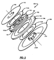
- FIG. 2 is a perspective view of an integrated suspension system interconnecting the tub assembly to the cabinet base in a laundry washing machine according to the present invention
- FIG. 3 is an enlarged portion of FIG. 2 showing an isolation damper assembly, associated with the integrated suspension system of the present invention, operably installed between the cabinet base and an outer tub mounting structure;
- FIGS. 4 and 5 are exploded perspective views of the isolation damper assembly in accordance with a preferred embodiment of the present invention.
- FIG. 6 is an assembled perspective view, with some components partially shown in section, of the isolation damper assembly shown in FIGS. 4 and 5;
- FIG. 7 is a top plan view of the isolation damper assembly
- FIG. 8 is a sectional view of the isolation damper assembly taken along line A-A in FIG. 7;
- FIG. 9 is an exploded perspective view of an isolation damper assembly constructed in accordance with an alternative preferred embodiment of the present invention.
- FIG. 10 is an assembled perspective view, with some components partially shown in section, of the isolation damper assembly shown in FIG. 9;
- FIG. 11 is an exploded perspective view of an isolation damper assembly constructed in accordance with another alternative preferred embodiment of the present invention.
- FIGS. 12 and 13 are sectional views, similar to FIG. 8, of isolation damper assemblies according to yet further alternative preferred embodiments of the present invention.
- the present invention is directed to an improved suspension system for use in laundry washing machines that provides significant operational and cost advantages over conventional spring-type suspension systems.
- a conventional washing machine will initially be described with reference to FIG. 1 of the drawings so as to clearly define the current state of the art.
- a typical top-loading washing machine includes a cabinet 10 having a housing with four sidewalls 11 which extend upwardly from a base 12.
- a top enclosure 14 is shown to be mounted to cabinet 10 on top of sidewalls 11.
- Top enclosure 14 has a central recessed portion 15 which defines an access opening 16 that is covered by a hinged lid 17.
- a control panel 18 is mounted to top enclosure 14 and includes a plurality of control members (i.e., dials, knobs, push buttons, etc.) for permitting selection of the desired washing cycles and water temperatures in a well-known manner.
- the washing machine mechanism is shown to include a tub assembly having an outer tub 20 and a drive assembly 22 that are resiliently mounted to base 12 via a suspension system 24.
- Drive assembly 22 includes a transmission 26 that is centrally located below outer tub 20 and an electric motor 28 for driving transmission 26 via a drive belt 30,
- Suspension system 24 includes a support frame 32 having a ring member 34 and a plurality of braces 36. Braces 36 are equally spaced and have a first end rigidly secured to outer tub 20 and a second end rigidly secured to ring member 34.
- ring member 34 defines a recessed cup segment 38 which is aligned with a central dome 40 formed in base 12.
- a suitable low-friction centering member commonly referred to as a snubber ring 42, is disposed in the annular space between cup segment 38 of ring member 34 and dome segment 40 of base 12.
- This ball socket type arrangement allows outer tub 20 to pivot about a vertical axis "Z" located at the center of dome segment 40 with snubber ring 42 acting to damp movement therebetween.
- Suspension system 24 further includes a plurality of centering springs 46 which each extend from brace 36 down to a position on the outermost edge of base 12. Centering springs 46 function to bias support frame 32 and outer tub 20 to a centered position aligned with the vertical axis while also inhibiting rotation of outer tub 20 relative to base 12. In many arrangements, at least six centering springs 46 are used to provide the requisite self-centering function.
- the tub assembly of the washing machine mechanism is shown to further include a perforated spin basket 48 that is mounted inside outer tub 20 for rotation about the vertical axis and which is driven by motor 28 through transmission 26.
- Transmission 26 also drives an agitator 50 (shown in phantom) which extends upwardly within spin basket 48.
- a pump 52 is mounted on motor 28 and is operable to control the delivery and drainage of water to and from spin basket 48 during operation of the washing machine.
- transmission 26 is mounted to cross brackets 54 which, in turn, are connected to braces 36 such that transmission 26 is supported by support frame 32.
- motor 28 is mounted to a support plate 56 that is also part of support frame 32.
- a weighted balance ring 58 is attached to the open upper end of spin basket 48 such that its central aperture 60 is aligned with access opening 16 of top enclosure 14.
- a tub cover 62 is attached to the open upper end of outer tub 20 and has a central aperture 64 which is also aligned with access opening 16 in top enclosure 14,
- Operation of the washing machine is conventional in that it functions in either a wash mode or a spin mode.
- transmission 26 is shifted into a first stage for oscillating agitator 50 at low speeds within spin basket 48 which is filled with clothes, water, and detergent.
- transmission 26 is shifted into a second stage for rotating spin basket 48 at a high speed so as to establish the spin cycle.
- the clothes are thrown by centrifugal force against spin basket 48 and the water drains through the perforations into outer tub 20 and is subsequently pumped out of the washing machine.
- the present invention is generally directed to an improved suspension system for laundry washing machines.
- the improved suspension system of the present invention is well-suited for use with top-loading washing machines having a construction generally similar to the washing machine shown in FIG. 1.
- the improved suspension system of the present invention functions to eliminate the dome-type pivot arrangement and the centering springs while providing superior vibration isolation and damping characteristics.
- FIGS. 2 through 8 disclose an integrated suspension system 100 that is applicable for use in laundry washing machines.
- Integrated suspension system 100 is comprised of a support frame 102 interconnected to outer tub 20 and an isolation damper assembly 104 resiliency coupling support frame 102 to base 12' of cabinet 10.
- Support frame 102 is generally similar to support frame 32 shown in FIG. 1 in that it supports the entire tub assembly as well as the drive components.
- support name 102 includes an annular ring 34' and a plurality of equidistantly-spaced braces 36' rigidly secured thereto. The upper end of each brace 36' is either directly secured to outer tub 20 or, in the alternative, secured to an upper plate or ring that is then secured to outer tub 20.
- support frame 102 is not critical to the present invention, but rather it functions to interconnect outer tub 20 to isolation damper assembly 104 and support the various drive components. Thus, any frame or support arrangement which provides these functions will be considered an equivalent to the support structure shown.
- isolation damper assembly 104 provides several integrated functions including allowing limited lateral movement of tub 20 relative to base 12'; providing a mechanism for returning tub 20 to a centered position within cabinet 10; and absorbing vibration transmitted through tub 20 and support frame 102 and/or the other components attached thereto.
- the integration of these functions into isolation damper assembly 104 results in a significant reduction in the overall cost of the suspension system by eliminating components and simplifying the assembly process and permits its use with only minor redesign of some of the components currently used in production laundry appliances.
- isolation damper assembly 104 is installed in substitution for snubber ring 42 and centering springs 46.
- isolation damper assembly 104 includes a lower case member 106, a mounting ring 108, a resilient isolator 110, an upper case member 112 and a pair of glide rings 114A and 114B.
- Lower case member 106 is adapted to be secured to base 12' of cabinet 10.
- Base 12' is a modified version of conventional base 12 in that central domed segment 40 of base 12 has been eliminated and replaced with a circular recessed portion that is adapted to accept receipt of a circular cup segment 116 of lower case member 106.
- cup segment 116 with the complimentary recessed portion of base 12' functions to centrally align isolation damper assembly 104 on the vertical "Z" axis of the washing machine mechanism.
- lower case member 106 can be planar with cup segment 116 eliminated for direct connection to a planar portion of base 12'.
- Lower case member 106 is also shown to include an outer rim segment 118 and an upstanding tubular hub segment 119, It is contemplated that outer rim segment 118 will be non-rotatably secured via suitable fasteners (i.e., bolts, clips, etc.) to base 12'.
- outer rim segment 118 will have tabs that can be inserted into corresponding slots in base 12' to define a releasable rotary-type quick connect fastening arrangement which facilitates easy installation and service.
- isolator 110 is shown to include a contoured central aperture defining a plurality of tooth-shaped projections or lobes 120, a first or upper annular channel 122A adapted to receive glide ring 114A, a second or lower annular channel 122B adapted to receive glide ring 114B, and a continuous peripheral groove 124 formed in its outer edge surface 126.
- isolation damper assembly 104 When isolation damper assembly 104 is fully assembled, the terminal end of lobes 120 on isolator 110 engage an outer wall surface of tubular hub segment 119 of lower case member 106.
- an anti-rotation feature can be provided by forming vertical channels in cylindrical hub segment 119 which are sized to seat the terminal end of each lobe 120 therein, thereby preventing rotation of isolator 110 relative to lower case member 106.
- isolator 110 has at least three equally spaced lobes 120 with the specific number thereof selected based on the needs of the particular application.
- isolator 110 is preferably fabricated from a microcellular polyurethane (MCU) material.
- MCU microcellular polyurethane
- the MCU material is preferred since it provides several advantageous features including superior vibration isolation characteristics, mechanical durability, resistance to most environmental fluids (i.e., oil, grease, ozone, water, etc.) and its low mass.
- the MCU material has a wide operating temperature range and low compression set characteristics.
- the MCU material can be "tuned” by changing the material density within a common mold in order to obtain the optimal isolation properties for each specific application.
- isolator 110 can be assembled from a plurality of isolator segments that are retained between case members 106 and 112.
- mounting ring 108 has a thick outer ring segment 130 and a thin inner ring segment 132.
- Outer ring segment 130 is adapted for connection with ring 34' of support frame 102.
- inner ring segment 132 is adapted for installation in groove 124 of isolator 110, thereby establishing a slip fit connection between isolator 110 and mounting ring 108.
- This slip fit acts to inhibit lateral movement of outer tub 20 and support frame 102 relative to base 12' until the force exerted thereon is great enough to cause radial compression of isolator 110.
- FIG. 1 As best seen in FIG.
- edge surface 133 of inner ring segment 132 abuts, or is in close proximity to, a terminal end surface 125 of groove 124.
- a raised shoulder surface 131 of outer ring segment 130 abuts, or is in close proximity to, end surface 126 of isolator 110.
- lateral movement of mounting ring 108 relative to isolator 110 will result in a radially directed compressive force being applied to isolator 110 which functions to resist excessive lateral movement of the tub assembly relative to base 12'.
- outer ring 34' of support frame 102 is attached to outer ring segment 130 of mounting ring 108 by conventional fasteners or, in the alternative, via a quick connect type of arrangement.
- Mounting ring 108 can be fabricated from any material providing the requisite strength and rigidity.
- mounting ring 108 is a stamped or powdered metal component.
- isolation damper assembly 104 also includes an upper case member 112 that is shown to include a planar ring segment 140 and a central tubular hub segment 142.
- Ring segment 140 has a planar inner face surface 144 adapted to slidingly engage corresponding outer face surfaces 146 and 148 of isolator 110 and upper glide ring 114A, respectively.
- upper glide ring 114A is used to control the sliding friction between isolator 110 and upper case member 112.
- lower glide ring 114B permits a controlled amount of sliding friction between isolator 110 and lower case member 106.
- an outer face surface 150 of central cup segment 116 in lower case member 106 engages a face surface 152 of glide ring 114B and a face surface 154 of isolator 110.
- tubular hub segment 142 on upper case member 112 is sized to overlap and engage hub segment 119 on lower case member 106.
- lower case member 106 and upper case member 112 are designed to slightly compress isolator 110 therebetween so as to allow for vibration isolation.
- means are provided for securing upper case member 112 to lower case member 106 for maintaining the desired compressive pre-load on isolator 110.
- a joint 156 is shown between hub segment 142 of upper case member 112 and hub segment 119 of lower case member 106. This joint is intended to be representative of a rigid coupling which can be established via a suitable fastening mechanism such as, for example, adhesives, welds, crimping, peening, rivets, screws, interlocking tabs, etc.
- Isolator 110 performs a umber of functions within isolation damper assembly 104.
- the compression of isolator 110 between case members 106 and 110 provides for vibration isolation and prevents rotation of support frame 102 relative to base 12'.
- the lobed aperture configuration permits lateral movement while also providing a retum-to-center function since the compressed lobe will "push back", thereby forcing support frame 102 to return to its centered position.
- the terminal ends of lobes 120 are slightly pre-loaded in a radial direction due to engagement with the outer wall surface of hub segment 119 on lower case member 106 so as to establish the normal centered position of the tub assembly along the "Z" axis.
- isolation damper assembly 104 hereinafter referred to by reference numeral 204, is shown to provide an anti-rotation feature between isolator 110 and a lower case member 206. Due to the commonality of most components, the same reference numerals are used to identify those components of isolation damper assembly 204 that are common to those of isolation damper assembly 104. As seen, upstanding hub segment 219 on lower case member 206 is generally cylindrical but is contoured to define a radially outwardly extending lug projection 219A.
- isolation damper assembly 204 Upon assembly of the components associated with isolation damper assembly 204, lug projection 219A is disposed between a pair of lobes 120 of resilient isolator 110 so as to prevent relative rotation between isolator 110 and lower case member 206.
- lug projection 219A is disposed between a pair of lobes 120 of resilient isolator 110 so as to prevent relative rotation between isolator 110 and lower case member 206.
- an alternative embodiment of an isolation damper assembly 304 is shown which also has many components that are common to those previsouly described in association with isolation damper assembly 104.
- lower case member 306 has an upstanding hub segment 319 contoured to define a plurality of radially outwardly extending lobe projections 319A while resilient isolator 310 has a generally cylindrical central aperture 320.
- isolator damper assembly 304 is fully assembled, the terminal ends of lobe projections 319A will engage the wall surface of aperture 320. Preferably, such engagement results in a slight compressive load being applied to isolator 310 at its localized points of contact with lobe projections 319A.
- This reversed lobe configuration still functions to permit limited lateral movement of support frame 102 relative to isolator 310 as well as a return-to-center function since the resiliency of the material used for isolator 310 will forcibly bias support frame 102 to return to its centered position along the "Z" axis.
- hub segment 319 of lower case member 306 includes a series of radially inwardly extending lugs 319B which interconnect adjacent pairs of lobes 319A.
- the outer wall surface of cylindrical hub segment 142 on upper case member 112 is adapted to engage the terminal ends of lugs 319B so as to provide an interface for rigidly securing upper case member 112 to lower case member 306.
- aperture 320 in isolator 310 is shown to include an inwardly extending tang segment 321 that is adapted to be disposed in the channel defined by one of lugs 319B between, a pair of lobes 319A, thereby providing an anti-rotation feature between isolator 310 and lower case member 3 06.
- isolation damper assembly 104 is illustrated and identified by reference numeral 104'.
- glide rings 114A and 114B have been eliminated such that isolator 110' does not include annular upper and lower channels 122A and 122B, respectively.
- face surfaces 146' and 154' of isolator 110' are now radially extended so as to respectively engage inner face surface 144 of upper case member 112 and outer face surface 150 of lower case member 106.
- sliding friction between isolator 110' and the interconnected case members can be tuned by the frictional characteristics of the material used for isolator 110' and the magnitude of the radial compressive preload applied to isolator 110' between plate segments 140 and 116 of the assembled case members.
- the width of inner ring segment 132' of mounting ring 108' has been reduced such that its terminal edge 133' is displaced from end surface 125 of groove 124. As such, all lateral loading is applied to isolator 110' at its end surface 126 via engagement with radial shoulder surface 131 of mounting ring 108'.
- FIG. 13 illustrates another modified version of isolation damper assembly 104 which is identified as isolation damper assembly 104".
- isolation damper assembly 104" is arranged to have a mounting ring 108" with its radial should 131" displaced from engagement with end surface 126 of isolator 110 while its inner edge surface 133 is in abutting contact with terminal end 125 of groove 124 in isolator 110. As such, all lateral loading is applied to isolator 110 at its end surface 125 via engagement with edge surface 133 of mounting ring 108".
- isolation damper assemblies of the present invention have been disclosed in an exemplary, non-limiting washing machine application.
- advantageous features associated with these isolation damper assemblies are well-suited for a plethora of other commercial application.
- Such commercial applications include, but are not limited to, industrial mixers/shakers, paint shakers, vibrating bowl feeders, vibrating cooling towers, and industrial vibratory and media polishing equipment.
Landscapes
- Engineering & Computer Science (AREA)
- Textile Engineering (AREA)
- Main Body Construction Of Washing Machines And Laundry Dryers (AREA)
- Vibration Prevention Devices (AREA)
Applications Claiming Priority (2)
| Application Number | Priority Date | Filing Date | Title |
|---|---|---|---|
| US811339 | 2004-03-26 | ||
| US10/811,339 US7290414B2 (en) | 2004-03-26 | 2004-03-26 | Integrated laundry suspension system |
Publications (1)
| Publication Number | Publication Date |
|---|---|
| EP1580312A2 true EP1580312A2 (de) | 2005-09-28 |
Family
ID=34862126
Family Applications (1)
| Application Number | Title | Priority Date | Filing Date |
|---|---|---|---|
| EP05006236A Withdrawn EP1580312A2 (de) | 2004-03-26 | 2005-03-22 | Integriertes Aufhängungssystem eines Laugenbehälters einer Wäschewaschmaschine |
Country Status (7)
| Country | Link |
|---|---|
| US (1) | US7290414B2 (de) |
| EP (1) | EP1580312A2 (de) |
| JP (1) | JP2005279272A (de) |
| KR (1) | KR20060044778A (de) |
| BR (1) | BRPI0501105A (de) |
| CA (1) | CA2501356A1 (de) |
| TW (1) | TW200536983A (de) |
Cited By (1)
| Publication number | Priority date | Publication date | Assignee | Title |
|---|---|---|---|---|
| USD1012388S1 (en) * | 2022-01-11 | 2024-01-23 | Mary Thomas | Washing machine for clothes |
Families Citing this family (12)
| Publication number | Priority date | Publication date | Assignee | Title |
|---|---|---|---|---|
| DE102005031487B3 (de) * | 2005-07-04 | 2006-07-13 | Miele & Cie. Kg | Waschmaschine mit Transportsicherung |
| DE102005031488B3 (de) * | 2005-07-04 | 2006-08-17 | Miele & Cie. Kg | Waschmaschine mit einer Transportsicherung |
| JP2008154313A (ja) * | 2006-12-14 | 2008-07-03 | Samsung Electronics Co Ltd | 電動モータの制御装置及びこれを備える洗濯機 |
| RU2415212C1 (ru) * | 2007-03-29 | 2011-03-27 | Арчелык Аноним Ширкети | Стиральная машина |
| KR101224396B1 (ko) * | 2007-11-06 | 2013-01-22 | 삼성전자주식회사 | 감쇠부재 및 이를 구비한 세탁기 |
| US9010159B2 (en) | 2010-04-13 | 2015-04-21 | Whirlpool Corporation | Laundry treating appliance with tub ring |
| KR102426087B1 (ko) * | 2017-11-29 | 2022-07-28 | 엘지전자 주식회사 | 세탁기 |
| EP3797189B1 (de) | 2018-05-21 | 2023-10-04 | Electrolux Appliances Aktiebolag | Wäschebehandlungsvorrichtung |
| US11976403B2 (en) | 2019-06-21 | 2024-05-07 | Electrolux Appliances Aktiebolag | Laundry treating appliance |
| CN114729493A (zh) * | 2019-11-18 | 2022-07-08 | 伊莱克斯家用电器股份公司 | 具有改善的洗涤性能的洗衣机 |
| EP4061990A1 (de) | 2019-11-18 | 2022-09-28 | Electrolux Appliances Aktiebolag | Wäschebehandlungsgerät mit dampf- und/oder nebel- und/oder aerosolgenerator |
| WO2021098944A1 (en) * | 2019-11-18 | 2021-05-27 | Electrolux Appliances Aktiebolag | Laundry washing machine with improved washing performances |
Family Cites Families (17)
| Publication number | Priority date | Publication date | Assignee | Title |
|---|---|---|---|---|
| US2969172A (en) * | 1956-05-16 | 1961-01-24 | Easy Washing Machine Company L | Clothes washing machine |
| DE1290908B (de) * | 1961-08-23 | 1969-03-20 | Tech Fortschritt Mbh Ges | Trommelwaschmaschine |
| US3108465A (en) * | 1962-10-29 | 1963-10-29 | Gen Electric | Clothes washing machine having vibration isolating means |
| US3285419A (en) * | 1963-06-04 | 1966-11-15 | Maytag Co | Extractor apparatus drive control |
| US3277742A (en) * | 1964-09-22 | 1966-10-11 | Westinghouse Electric Corp | Clothes washer |
| US3475928A (en) * | 1968-01-22 | 1969-11-04 | Westinghouse Electric Corp | Clothes washing machine |
| US3952557A (en) * | 1974-06-20 | 1976-04-27 | General Electric Company | Wobble washing machine |
| US4250724A (en) * | 1979-01-10 | 1981-02-17 | Raytheon Company | Suspension system for tub assembly in clothes washing machine |
| US4475363A (en) * | 1983-06-06 | 1984-10-09 | General Electric Company | Adjustable dual node support assembly for washing machine |
| US4468938A (en) * | 1983-09-12 | 1984-09-04 | General Electric Company | Tubless washing machine |
| US4502303A (en) * | 1983-10-31 | 1985-03-05 | White Consolidated Industries, Inc. | Washing machine tub construction |
| SE9301396L (sv) * | 1993-04-26 | 1994-10-27 | Electrolux Ab | Anordning vid en tvättmaskin för dämpning av vibrationsljud |
| US5377508A (en) | 1994-02-09 | 1995-01-03 | Maytag Corporation | Apparatus and method for providing dual washing capacity |
| US5946947A (en) * | 1996-05-21 | 1999-09-07 | Samsung Electronics Co., Ltd. | Clothes washing machine having vibration and noise damper |
| KR19980085150A (ko) | 1997-05-28 | 1998-12-05 | 배순훈 | 세탁기의 교반장치 |
| US6220063B1 (en) | 1999-02-09 | 2001-04-24 | Maytag Corporation | Drive system for clothes washer |
| DE19921152A1 (de) * | 1999-05-07 | 2000-11-09 | Suspa Compart Ag | Anlenk-Vorrichtung zur Anlenkung eines Reibungsdämpfers an einem Maschinengestell einer Waschmaschine |
-
2004
- 2004-03-26 US US10/811,339 patent/US7290414B2/en not_active Expired - Fee Related
-
2005
- 2005-03-18 CA CA002501356A patent/CA2501356A1/en not_active Abandoned
- 2005-03-22 EP EP05006236A patent/EP1580312A2/de not_active Withdrawn
- 2005-03-23 TW TW094108942A patent/TW200536983A/zh unknown
- 2005-03-24 BR BR0501105-1A patent/BRPI0501105A/pt not_active IP Right Cessation
- 2005-03-25 KR KR1020050025048A patent/KR20060044778A/ko not_active Ceased
- 2005-03-28 JP JP2005090320A patent/JP2005279272A/ja active Pending
Cited By (1)
| Publication number | Priority date | Publication date | Assignee | Title |
|---|---|---|---|---|
| USD1012388S1 (en) * | 2022-01-11 | 2024-01-23 | Mary Thomas | Washing machine for clothes |
Also Published As
| Publication number | Publication date |
|---|---|
| BRPI0501105A (pt) | 2005-11-01 |
| TW200536983A (en) | 2005-11-16 |
| US20050210603A1 (en) | 2005-09-29 |
| KR20060044778A (ko) | 2006-05-16 |
| CA2501356A1 (en) | 2005-09-26 |
| US7290414B2 (en) | 2007-11-06 |
| JP2005279272A (ja) | 2005-10-13 |
Similar Documents
| Publication | Publication Date | Title |
|---|---|---|
| US7290414B2 (en) | Integrated laundry suspension system | |
| US5269160A (en) | Self-centering drive system for an automatic washer | |
| US6397643B1 (en) | Suspension apparatus of washing machine | |
| EP2573249B1 (de) | Trommelwaschmaschine | |
| US8225628B2 (en) | Drum-type washing machine | |
| KR100398006B1 (ko) | 자동세탁기의개선된현가시스템 | |
| US5657649A (en) | Full-automatic washing machine having a vibration damping assembly | |
| KR200151035Y1 (ko) | 드럼형 세탁기의 진동 및 소음 감소장치 | |
| US7310978B2 (en) | Drum-type washing machine with elastic oil damper | |
| EP0808933A2 (de) | Waschmaschine | |
| EP2435615B1 (de) | Waschmaschine | |
| US7454928B2 (en) | Multi-component isolation damping system for a laundry washing machine | |
| US5816074A (en) | Balancing device for a drum washing machine | |
| US3779090A (en) | Washing machine | |
| JPH08215477A (ja) | 電気洗濯機の防振装置 | |
| US5117658A (en) | Washing machine having improved out-of-balance performance | |
| US20230212806A1 (en) | Suspension mount for a top load washing machine | |
| EP0212259B1 (de) | Laugenbehälter mit aus verschiedenen Materialien zusammengesetzter Struktur für eine von oben beschickbare Waschmaschine | |
| EP1526212A2 (de) | Waschmaschinen | |
| JP3747486B2 (ja) | 全自動洗濯機の防振装置 | |
| JP2015107197A (ja) | 洗濯機 | |
| JP3183125B2 (ja) | 全自動洗濯機 | |
| JP2004084921A (ja) | 防振支持装置 | |
| KR200145372Y1 (ko) | 드럼세탁기의 밸런싱장치 | |
| KR100228627B1 (ko) | 전자동 탈수 세탁기 |
Legal Events
| Date | Code | Title | Description |
|---|---|---|---|
| PUAI | Public reference made under article 153(3) epc to a published international application that has entered the european phase |
Free format text: ORIGINAL CODE: 0009012 |
|
| AK | Designated contracting states |
Kind code of ref document: A2 Designated state(s): AT BE BG CH CY CZ DE DK EE ES FI FR GB GR HU IE IS IT LI LT LU MC NL PL PT RO SE SI SK TR |
|
| AX | Request for extension of the european patent |
Extension state: AL BA HR LV MK YU |
|
| STAA | Information on the status of an ep patent application or granted ep patent |
Free format text: STATUS: THE APPLICATION IS DEEMED TO BE WITHDRAWN |
|
| 18D | Application deemed to be withdrawn |
Effective date: 20071002 |