EP0808718A2 - Kopfkassette für einen Tintenstrahldrucker - Google Patents
Kopfkassette für einen Tintenstrahldrucker Download PDFInfo
- Publication number
- EP0808718A2 EP0808718A2 EP97303447A EP97303447A EP0808718A2 EP 0808718 A2 EP0808718 A2 EP 0808718A2 EP 97303447 A EP97303447 A EP 97303447A EP 97303447 A EP97303447 A EP 97303447A EP 0808718 A2 EP0808718 A2 EP 0808718A2
- Authority
- EP
- European Patent Office
- Prior art keywords
- ink
- head cartridge
- cap
- latch assembly
- cartridge according
- Prior art date
- Legal status (The legal status is an assumption and is not a legal conclusion. Google has not performed a legal analysis and makes no representation as to the accuracy of the status listed.)
- Granted
Links
Images

Classifications
-
- B—PERFORMING OPERATIONS; TRANSPORTING
- B41—PRINTING; LINING MACHINES; TYPEWRITERS; STAMPS
- B41J—TYPEWRITERS; SELECTIVE PRINTING MECHANISMS, i.e. MECHANISMS PRINTING OTHERWISE THAN FROM A FORME; CORRECTION OF TYPOGRAPHICAL ERRORS
- B41J2/00—Typewriters or selective printing mechanisms characterised by the printing or marking process for which they are designed
- B41J2/005—Typewriters or selective printing mechanisms characterised by the printing or marking process for which they are designed characterised by bringing liquid or particles selectively into contact with a printing material
- B41J2/01—Ink jet
- B41J2/17—Ink jet characterised by ink handling
- B41J2/175—Ink supply systems ; Circuit parts therefor
- B41J2/17503—Ink cartridges
- B41J2/1752—Mounting within the printer
-
- B—PERFORMING OPERATIONS; TRANSPORTING
- B41—PRINTING; LINING MACHINES; TYPEWRITERS; STAMPS
- B41J—TYPEWRITERS; SELECTIVE PRINTING MECHANISMS, i.e. MECHANISMS PRINTING OTHERWISE THAN FROM A FORME; CORRECTION OF TYPOGRAPHICAL ERRORS
- B41J2/00—Typewriters or selective printing mechanisms characterised by the printing or marking process for which they are designed
- B41J2/005—Typewriters or selective printing mechanisms characterised by the printing or marking process for which they are designed characterised by bringing liquid or particles selectively into contact with a printing material
- B41J2/01—Ink jet
- B41J2/17—Ink jet characterised by ink handling
- B41J2/175—Ink supply systems ; Circuit parts therefor
- B41J2/17503—Ink cartridges
- B41J2/17506—Refilling of the cartridge
-
- B—PERFORMING OPERATIONS; TRANSPORTING
- B41—PRINTING; LINING MACHINES; TYPEWRITERS; STAMPS
- B41J—TYPEWRITERS; SELECTIVE PRINTING MECHANISMS, i.e. MECHANISMS PRINTING OTHERWISE THAN FROM A FORME; CORRECTION OF TYPOGRAPHICAL ERRORS
- B41J2/00—Typewriters or selective printing mechanisms characterised by the printing or marking process for which they are designed
- B41J2/005—Typewriters or selective printing mechanisms characterised by the printing or marking process for which they are designed characterised by bringing liquid or particles selectively into contact with a printing material
- B41J2/01—Ink jet
- B41J2/17—Ink jet characterised by ink handling
- B41J2/175—Ink supply systems ; Circuit parts therefor
- B41J2/17503—Ink cartridges
- B41J2/17513—Inner structure
Definitions
- the present invention generally relates to an ink-jet printer. More particularly, it relates to a head cartridge assembly for an ink-jet printer.
- a head cartridge 21, for a conventional ink-jet printer is installed on a carriage that slides right and left on a rail inside the printer's main body, and includes an ink storage 23 inside an ink vessel body 22.
- a flexible body 24 is installed within ink storage 23, and an ink filter 26 is located on the bottom of the interior of ink storage 23.
- a heating device 27 and a nozzle 28 containing a spray hole 29 are located under ink filter 26.
- a cap 30 is attached to ink vessel body 22 by an ultrasonic bonding process.
- An ink filling hole 25 is drilled in the middle of cap 30, through which ink storage 23 is refilled with ink.
- a locking portion 31 is formed on one side of cap 30, protruding upward so as to mate with the main body carriage of the printer (not illustrated).
- Head cartridge 21 includes a heating device 27, with an array of heating elements for heating ink.
- a nozzle 28 has a spray hole 29 with multiple orifices for spraying ink particles onto the print media by heating and vaporization of the ink.
- An electrode section is the means for furnishing electrical power to heating device 27.
- a flexible body 24 stores ink in the ink storage 23.
- a cap 30 is attached to ink vessel body 22, which provides protection for flexible body 24.
- Ink particles, introduced to the heating elements of heating device 27, are vaporized by heat to produce a vapour pressure.
- This vapour pressure causes these ink particles to spray onto print media through spray hole 29.
- a negative pressure acts on spray hole 29, by the meniscus phenomenon, the pressure on flexible body 24 that is being compressed to ink filter 26 causes the creation of positive pressure, atmospheric pressure, owing to a hole in the ink vessel body connected with the atmosphere, so that ink particles are introduced to the heating elements of heating device 27.
- the user takes the head cartridge 21 from the carriage and replaces it with a new one, or refills the ink storage 23 through ink filling hole 25 located on cap 30.
- the conventional ink-jet printer head cartridge is disposable, and parts other than the head cartridge may affect the life of the printer head. In general, the life of the head is the period between being installed in the printer and the time when the internal heating device is damaged by chemical interaction and electrolytic action with ink particles, whereby the nozzle fails to spray ink particles.
- the heating device uses about 35g of the original 43g of ink, and 6 to 10g of ink remains on the flexible body.
- the conventional head cartridge is designed to be reused six times by refilling ink. However, the cartridge can fail due to the spray hole being plugged by dirt.
- the present invention provides a head cartridge for an ink-jet printer comprising an ink vessel body having an ink filling hole and a latch assembly mounted on the ink vessel body to plug the ink filling hole.
- the ink filling hole may be located on a cap which is attached to the top of the ink vessel body and the latch assembly is mounted on the cap.
- the cap may be attached to the top of the ink vessel body by ultrasonic bonding.
- the latch assembly may comprise a downward protruding stopper at one end and a lug at the other end adapted to lock into an opening on the cap.
- the opening on the cap may be located on one side of it and the lug on the latch assembly is adapted to fit into the opening, locking the latch assembly securely to the cap.
- the latch assembly may have a groove formed across it and located away from the stopper so that the latch assembly can be easily mounted on and removed from the cap. The groove is preferably loaded in tension and is designed to be easily cut.
- the latch assembly may also include a locking portion formed above the lug and adapted to lock the head cartridge into a carriage of the main body of the printer.
- the head cartridge may further comprise an ink storage inside the ink vessel body, a flexible body inside the ink storage adapted to hold and deliver ink, an ink filter located inside the ink storage towards the bottom, a heating device with one or more heating elements located under the ink filter to heat and vaporize the ink in the ink storage and a nozzle having a spray hole with one or more orifices for spraying ink particles onto print media using pressure caused by the heating device vaporizing the ink.
- a sponge may serve as the flexible body of the ink storage.
- the ink filter preferably has a very fine mesh to filter out substances other than ink.
- the ink filling hole may also serve as an air hole or the ink vessel body may further include an air hole on its upper portion to equalize the pressure inside said cap with atmospheric pressure.
- the ink filling hole is 1 to 5mm in diameter, preferably 1.5mm.
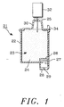
- a head cartridge 1, for an ink-jet printer is attached to a carriage in the main body of the printer, and has an ink storage 3 located inside an ink vessel body 2.
- Ink storage 3 includes a flexible body 4 for ink storage and ink conveyance, an ink filter 6 located on a lower portion inside of ink storage 3, a heating device 7, with multiple heating elements, installed under ink filter 6, which filters the ink flowing into heating device 7, to heat and vaporize ink, a nozzle 8 having a spray hole 9, with multiple of orifices, for spraying ink particles onto the print media and electrical contacts for supplying energy to heating device 7.
- An ink filling hole 5 and an opening 11 are formed on a cap 10 which is attached to ink vessel body 2 by an ultrasonic bonding process to provide protection for flexible body 4.
- a latch assembly 12 containing a stopper or lid 13, for sealing ink filling hole 5, and a locking portion 14, for locking the head cartridge in the carriage, which are integrally formed.
- latch assembly 12 consists of stopper 13 formed on one end to protrude downward, locking portion 14 formed on the other end to lock the head cartridge into the main body carriage (not illustrated), and a lug 15 under locking portion 14 which locks into an opening 11.
- Latch assembly 12 has a concave portion 16 on the top which is located away from lid 13 so as to facilitate mounting or removing latch assembly 12 from cap 10. Concave portion 16 is designed to be cut easily.
- Ink storage 3 holds flexible body 4 and ink, and a sponge serves as the flexible body 4.
- Ink filling hole 5 may be used as an air hole, and an extra air hole may be formed on cap 10 for equalizing the internal pressure with atmospheric.
- Ink filling hole 5 is of 1 to 5mm in diameter, though 1.5mm is the optimum size.
- head cartridge 1 the ink flowing into the heating elements of heating device 7, is vaporized by the heat, and the vapour pressure created at the time of the vaporization, forces ink particles to spray onto the print media through spray hole 9. Simultaneously, a negative pressure is created by the meniscus phenomenon around spray hole 9, the pressure acting on flexible body 4 that is being compressed to ink filter 6 causes the creation of positive pressure, atmospheric pressure, owing to an air hole connected with the atmosphere. This causes ink particles contained in flexible body 4 to be introduced into the heating elements to be sprayed onto the print media through the spray hole 9 of the nozzle 8.
- a predetermined amount of the ink of flexible body 4 is used by the repetition of the above cycle, thereby giving rise to loss of characters during printing.
- lid 13 can be separated from latch assembly 12 by cutting along grove 16 in latch assembly 12 so that locking portion 14 of latch assembly 12 is easily detached from the printer carriage and head cartridge 1 is then removed to be refilled with ink through ink filling hole 5 using ink injector 17.
- head cartridge 1 When the ink in head cartridge 1 is used up, head cartridge 1 is separated from the main body carriage, and latch assembly 12 is removed from cap 10. If 30 to 35g ink, the amount of ink used, is injected, using ink injector 17, through ink filling hole 5, it is delivered to and held in flexible body 4 by capillary action. If excess ink is injected to ink storage 3, it overflows through spray hole 9 of the nozzle 8. Therefore, refilling just as much ink as is used can prevent overflow of ink and contamination, and it is wise to refill ink after applying a tape to the spray hole 9 of nozzle 8.
- latch assembly 12 plugs ink filling hole 5 by insertion of lug 15 into opening 11. If head cartridge 1 is reinstalled in the printer after removal of the tape applied to spray hole 9, it is initialized by suction pumping and forced spraying in its first operation. Ink filling hole 5 is sealed by lid 13 of latch assembly 12 to prevent dirt and dust from getting into ink storage 3, thus avoiding the cartridge failure due to clogging of spray hole 9. In addition, when a user purchases the head cartridge 1, conveniently, he also has several ink injectors for further refilling the cartridge.
- the head cartridge has a latch assembly designed to plug the ink filling hole, thus preventing cartridge failure due to dirt and dust.
- the head cartridge is reused by refilling the proper amount of ink using an ink injector through the ink filling hole after removing the latch assembly, which assures a long life for the head cartridge.
- using the head cartridge along with the ink injector may offer great convenience and cost-effectiveness.
Landscapes
- Ink Jet (AREA)
Applications Claiming Priority (2)
| Application Number | Priority Date | Filing Date | Title |
|---|---|---|---|
| KR9617517 | 1996-05-22 | ||
| KR1019960017517A KR0174668B1 (ko) | 1996-05-22 | 1996-05-22 | 잉크젯 프린터의 헤드 카트리지 장치 |
Publications (3)
| Publication Number | Publication Date |
|---|---|
| EP0808718A2 true EP0808718A2 (de) | 1997-11-26 |
| EP0808718A3 EP0808718A3 (de) | 1998-06-03 |
| EP0808718B1 EP0808718B1 (de) | 2001-10-31 |
Family
ID=19459546
Family Applications (1)
| Application Number | Title | Priority Date | Filing Date |
|---|---|---|---|
| EP97303447A Expired - Lifetime EP0808718B1 (de) | 1996-05-22 | 1997-05-21 | Kopfkassette für einen Tintenstrahldrucker |
Country Status (6)
| Country | Link |
|---|---|
| US (1) | US6007192A (de) |
| EP (1) | EP0808718B1 (de) |
| JP (1) | JP3111039B2 (de) |
| KR (1) | KR0174668B1 (de) |
| CN (1) | CN1077508C (de) |
| DE (1) | DE69707751T2 (de) |
Cited By (4)
| Publication number | Priority date | Publication date | Assignee | Title |
|---|---|---|---|---|
| WO1998055325A1 (en) * | 1997-06-04 | 1998-12-10 | Hewlett-Packard Company | High performance ink container with efficient construction |
| EP0940258A1 (de) * | 1998-03-04 | 1999-09-08 | Hewlett-Packard Company | Tintenbehälternachfüllverfahren |
| FR2833517A1 (fr) * | 2001-12-14 | 2003-06-20 | Monitek Electronics Ltd | Cartouche d'encre |
| EP1232064A4 (de) * | 1999-11-22 | 2003-07-23 | Mitsubishi Chem America Inc | Tintenvorratsbehälter, nachfüllbehälter und nachfüllverfahren |
Families Citing this family (14)
| Publication number | Priority date | Publication date | Assignee | Title |
|---|---|---|---|---|
| JPH0588042U (ja) * | 1992-04-30 | 1993-11-26 | ミツミ電機株式会社 | コードレス電話装置 |
| TW514602B (en) * | 2001-03-16 | 2002-12-21 | Benq Corp | Ink container with a bubble accumulator chamber |
| JP2002370375A (ja) * | 2001-06-18 | 2002-12-24 | Canon Inc | インクジェットプリント装置、インクタンクおよびインク供給方法 |
| KR100491581B1 (ko) * | 2002-10-14 | 2005-05-27 | 삼성전자주식회사 | 재충전이 가능한 잉크 카트리지 |
| US20050088496A1 (en) * | 2003-10-22 | 2005-04-28 | Lui Pui K. | Ink refilling cap |
| US7448734B2 (en) | 2004-01-21 | 2008-11-11 | Silverbrook Research Pty Ltd | Inkjet printer cartridge with pagewidth printhead |
| BRPI0506191A (pt) * | 2004-11-29 | 2006-07-25 | Seiko Epson Corp | processo de reenchimento de cartucho, dispositivo de reenchimento de lìquido e cartucho de reenchimento |
| KR101280555B1 (ko) * | 2006-08-28 | 2013-07-02 | 삼성전자주식회사 | 화상형성장치의 현상유닛 |
| JP5011922B2 (ja) * | 2006-09-29 | 2012-08-29 | ブラザー工業株式会社 | インクカートリッジ及びインクジェット記録システム |
| CN108819488A (zh) * | 2018-07-16 | 2018-11-16 | 天津创天图文设计股份有限公司 | 新型打印机油墨填充装置 |
| JP7354572B2 (ja) * | 2019-04-10 | 2023-10-03 | セイコーエプソン株式会社 | 記録装置 |
| JP7467862B2 (ja) * | 2019-09-30 | 2024-04-16 | セイコーエプソン株式会社 | インクジェット記録装置、インクジェット記録方法、及び水性インク組成物 |
| WO2022071138A1 (en) | 2020-09-30 | 2022-04-07 | Brother Kogyo Kabushiki Kaisha | Liquid discharging apparatus |
| JP7790063B2 (ja) * | 2020-09-30 | 2025-12-23 | ブラザー工業株式会社 | 液体吐出装置 |
Family Cites Families (13)
| Publication number | Priority date | Publication date | Assignee | Title |
|---|---|---|---|---|
| GB2208227A (en) * | 1988-08-11 | 1989-03-15 | Ici Plc | Introducing additive into a container |
| DE4025319A1 (de) * | 1990-08-07 | 1992-02-13 | Siemens Ag | Tintendruckwerk und verfahren zum einmaligen befuellen des tintenvorratsbehaelters des tintendruckwerkes |
| US5233369A (en) * | 1990-12-27 | 1993-08-03 | Xerox Corporation | Method and apparatus for supplying ink to an ink jet printer |
| US5561450A (en) * | 1992-09-30 | 1996-10-01 | Pitney Bowes Inc. | Apparatus for mounting an ink jet cartridge on a support therefor |
| WO1994011195A1 (en) * | 1992-11-12 | 1994-05-26 | Graphic Utilities, Inc. | Method for refilling ink jet cartridges |
| JP3222294B2 (ja) * | 1993-01-01 | 2001-10-22 | キヤノン株式会社 | インク再充填容器及び該容器を用いたインク再充填方法 |
| DE4327178C1 (de) * | 1993-08-13 | 1995-03-09 | Pms Gmbh Prod & Recycling | Vorrichtung zum Wiederbefüllen eines Druckkopfs eines Tintenstrahldruckers |
| US5400573A (en) * | 1993-12-14 | 1995-03-28 | Crystal; Richard G. | Kit and method for opening, refilling and sealing a cartridge |
| US5572245A (en) * | 1994-03-10 | 1996-11-05 | Hewlett-Packard Company | Protective cover apparatus for an ink-jet pen |
| US5589861A (en) * | 1994-05-31 | 1996-12-31 | Hewlett-Packard Company | Cleaner cartridge for an inkjet printing mechanism |
| US5596358A (en) * | 1994-10-31 | 1997-01-21 | Hewlett-Packard Company | Method and apparatus for refilling a print cartridge having a reservoir pressure of less than ambient pressure |
| JP2817656B2 (ja) * | 1995-02-21 | 1998-10-30 | 富士ゼロックス株式会社 | インク供給装置および記録装置 |
| JP3117742U (ja) | 2005-10-18 | 2006-01-12 | さとみ 濱砂 | マスク |
-
1996
- 1996-05-22 KR KR1019960017517A patent/KR0174668B1/ko not_active Expired - Fee Related
-
1997
- 1997-05-21 EP EP97303447A patent/EP0808718B1/de not_active Expired - Lifetime
- 1997-05-21 DE DE69707751T patent/DE69707751T2/de not_active Expired - Fee Related
- 1997-05-22 JP JP09132654A patent/JP3111039B2/ja not_active Expired - Fee Related
- 1997-05-22 US US08/861,690 patent/US6007192A/en not_active Expired - Fee Related
- 1997-05-22 CN CN97113284A patent/CN1077508C/zh not_active Expired - Fee Related
Cited By (8)
| Publication number | Priority date | Publication date | Assignee | Title |
|---|---|---|---|---|
| US6017118A (en) * | 1995-04-27 | 2000-01-25 | Hewlett-Packard Company | High performance ink container with efficient construction |
| US6170937B1 (en) | 1997-01-21 | 2001-01-09 | Hewlett-Packard Company | Ink container refurbishment method |
| WO1998055325A1 (en) * | 1997-06-04 | 1998-12-10 | Hewlett-Packard Company | High performance ink container with efficient construction |
| EP0940258A1 (de) * | 1998-03-04 | 1999-09-08 | Hewlett-Packard Company | Tintenbehälternachfüllverfahren |
| US6283586B1 (en) | 1998-03-04 | 2001-09-04 | Hewlett-Packard Company | Method and apparatus for refilling ink containers in a manner that preserves printhead life |
| US6450629B2 (en) | 1998-03-04 | 2002-09-17 | Hewlett-Packard Company | Method and apparatus for refilling ink containers in a manner that preserves printhead life |
| EP1232064A4 (de) * | 1999-11-22 | 2003-07-23 | Mitsubishi Chem America Inc | Tintenvorratsbehälter, nachfüllbehälter und nachfüllverfahren |
| FR2833517A1 (fr) * | 2001-12-14 | 2003-06-20 | Monitek Electronics Ltd | Cartouche d'encre |
Also Published As
| Publication number | Publication date |
|---|---|
| EP0808718B1 (de) | 2001-10-31 |
| EP0808718A3 (de) | 1998-06-03 |
| JPH1044463A (ja) | 1998-02-17 |
| JP3111039B2 (ja) | 2000-11-20 |
| US6007192A (en) | 1999-12-28 |
| KR0174668B1 (ko) | 1999-05-15 |
| DE69707751T2 (de) | 2002-12-05 |
| KR970073981A (ko) | 1997-12-10 |
| CN1077508C (zh) | 2002-01-09 |
| DE69707751D1 (de) | 2001-12-06 |
| CN1172017A (zh) | 1998-02-04 |
Similar Documents
| Publication | Publication Date | Title |
|---|---|---|
| EP0808718B1 (de) | Kopfkassette für einen Tintenstrahldrucker | |
| TW520329B (en) | Method of filling an ink cartridge with ink and an apparatus thereof | |
| JP3183760B2 (ja) | インク容器、インクジェット記録ヘッド、インクジェットカートリッジおよびインクジェット記録装置 | |
| US8182075B2 (en) | Liquid delivery system and manufacturing method thereof | |
| JPH09123473A (ja) | インクジェットカートリッジを補充するための装置 | |
| JPH106521A (ja) | 液体補充方法、液体供給装置及び液体吐出記録装置 | |
| EP0999061A3 (de) | Behälter für eine Tintenstrahlaufzeichnungskopfkartusche und Verfahren zu seiner Lagerung | |
| EP2103436A2 (de) | Flüssigkeitsabgabesystem und Herstellungsverfahren dafür | |
| US6074049A (en) | Ink cartridge for a printing head of an inkjet printer | |
| WO1998040216A1 (en) | Ink supply apparatus and ink filling method | |
| JP3227271B2 (ja) | インク供給装置 | |
| JPH09123474A (ja) | 補充可能なインクジェットカートリッジ | |
| JP2839997B2 (ja) | 記録ヘッドユニット | |
| JP2002127440A (ja) | インクジェット式記録装置 | |
| KR100199473B1 (ko) | 잉크제트 프린터의 카트리지 구조 | |
| JP3092643B2 (ja) | インクジェット記録装置、及びインクカートリッジ | |
| CN103568574A (zh) | 盒的制造方法、盒的制造装置 | |
| KR100209516B1 (ko) | 잉크젯 프린트 헤드의 잉크 저장 장치 및 방법 | |
| JP3138121B2 (ja) | インクジェット装置用インクカートリッジへのインク注入装置 | |
| JPS5959457A (ja) | インクカ−トリツジおよび記録ヘツドの洗浄装置 | |
| JP2008207514A (ja) | インクジェット記録装置 | |
| KR100332609B1 (ko) | 잉크카트리지의잉크재충전방법및잉크재충전키트 | |
| JPS60198255A (ja) | 液体噴射記録装置 | |
| JP3175396B2 (ja) | インクジェット記録ヘッドカートリッジ | |
| JPS60206651A (ja) | 機器のインク供給方法および該方法を用いた液体噴射記録ヘッド |
Legal Events
| Date | Code | Title | Description |
|---|---|---|---|
| PUAI | Public reference made under article 153(3) epc to a published international application that has entered the european phase |
Free format text: ORIGINAL CODE: 0009012 |
|
| 17P | Request for examination filed |
Effective date: 19970605 |
|
| AK | Designated contracting states |
Kind code of ref document: A2 Designated state(s): DE FR GB IT |
|
| PUAL | Search report despatched |
Free format text: ORIGINAL CODE: 0009013 |
|
| AK | Designated contracting states |
Kind code of ref document: A3 Designated state(s): DE FR GB IT |
|
| 17Q | First examination report despatched |
Effective date: 19991111 |
|
| GRAG | Despatch of communication of intention to grant |
Free format text: ORIGINAL CODE: EPIDOS AGRA |
|
| GRAG | Despatch of communication of intention to grant |
Free format text: ORIGINAL CODE: EPIDOS AGRA |
|
| GRAH | Despatch of communication of intention to grant a patent |
Free format text: ORIGINAL CODE: EPIDOS IGRA |
|
| GRAH | Despatch of communication of intention to grant a patent |
Free format text: ORIGINAL CODE: EPIDOS IGRA |
|
| GRAA | (expected) grant |
Free format text: ORIGINAL CODE: 0009210 |
|
| AK | Designated contracting states |
Kind code of ref document: B1 Designated state(s): DE FR GB IT |
|
| REF | Corresponds to: |
Ref document number: 69707751 Country of ref document: DE Date of ref document: 20011206 |
|
| REG | Reference to a national code |
Ref country code: GB Ref legal event code: IF02 |
|
| ET | Fr: translation filed | ||
| PLBE | No opposition filed within time limit |
Free format text: ORIGINAL CODE: 0009261 |
|
| 26N | No opposition filed | ||
| PGFP | Annual fee paid to national office [announced via postgrant information from national office to epo] |
Ref country code: IT Payment date: 20090522 Year of fee payment: 13 Ref country code: FR Payment date: 20090515 Year of fee payment: 13 Ref country code: DE Payment date: 20090514 Year of fee payment: 13 |
|
| PGFP | Annual fee paid to national office [announced via postgrant information from national office to epo] |
Ref country code: GB Payment date: 20090520 Year of fee payment: 13 |
|
| GBPC | Gb: european patent ceased through non-payment of renewal fee |
Effective date: 20100521 |
|
| REG | Reference to a national code |
Ref country code: FR Ref legal event code: ST Effective date: 20110131 |
|
| PG25 | Lapsed in a contracting state [announced via postgrant information from national office to epo] |
Ref country code: IT Free format text: LAPSE BECAUSE OF NON-PAYMENT OF DUE FEES Effective date: 20100521 |
|
| PG25 | Lapsed in a contracting state [announced via postgrant information from national office to epo] |
Ref country code: DE Free format text: LAPSE BECAUSE OF NON-PAYMENT OF DUE FEES Effective date: 20101201 |
|
| PG25 | Lapsed in a contracting state [announced via postgrant information from national office to epo] |
Ref country code: FR Free format text: LAPSE BECAUSE OF NON-PAYMENT OF DUE FEES Effective date: 20100531 |
|
| PG25 | Lapsed in a contracting state [announced via postgrant information from national office to epo] |
Ref country code: GB Free format text: LAPSE BECAUSE OF NON-PAYMENT OF DUE FEES Effective date: 20100521 |
|
| REG | Reference to a national code |
Ref country code: GB Ref legal event code: 732E Free format text: REGISTERED BETWEEN 20170406 AND 20170412 |
|
| REG | Reference to a national code |
Ref country code: FR Ref legal event code: TP Owner name: S-PRINTING SOLUTION CO., LTD., KR Effective date: 20170912 |