EP0807930A1 - Appareil d'enregistrement de donnees, procede et appareil de reproduction de donnees - Google Patents
Appareil d'enregistrement de donnees, procede et appareil de reproduction de donnees Download PDFInfo
- Publication number
- EP0807930A1 EP0807930A1 EP96927873A EP96927873A EP0807930A1 EP 0807930 A1 EP0807930 A1 EP 0807930A1 EP 96927873 A EP96927873 A EP 96927873A EP 96927873 A EP96927873 A EP 96927873A EP 0807930 A1 EP0807930 A1 EP 0807930A1
- Authority
- EP
- European Patent Office
- Prior art keywords
- data
- sector
- error correction
- correction code
- instruction information
- Prior art date
- Legal status (The legal status is an assumption and is not a legal conclusion. Google has not performed a legal analysis and makes no representation as to the accuracy of the status listed.)
- Ceased
Links
Images


Classifications
-
- G—PHYSICS
- G11—INFORMATION STORAGE
- G11B—INFORMATION STORAGE BASED ON RELATIVE MOVEMENT BETWEEN RECORD CARRIER AND TRANSDUCER
- G11B19/00—Driving, starting, stopping record carriers not specifically of filamentary or web form, or of supports therefor; Control thereof; Control of operating function ; Driving both disc and head
- G11B19/02—Control of operating function, e.g. switching from recording to reproducing
-
- G—PHYSICS
- G11—INFORMATION STORAGE
- G11B—INFORMATION STORAGE BASED ON RELATIVE MOVEMENT BETWEEN RECORD CARRIER AND TRANSDUCER
- G11B20/00—Signal processing not specific to the method of recording or reproducing; Circuits therefor
- G11B20/10—Digital recording or reproducing
-
- G—PHYSICS
- G11—INFORMATION STORAGE
- G11B—INFORMATION STORAGE BASED ON RELATIVE MOVEMENT BETWEEN RECORD CARRIER AND TRANSDUCER
- G11B20/00—Signal processing not specific to the method of recording or reproducing; Circuits therefor
- G11B20/10—Digital recording or reproducing
- G11B20/12—Formatting, e.g. arrangement of data block or words on the record carriers
- G11B20/1217—Formatting, e.g. arrangement of data block or words on the record carriers on discs
- G11B20/1251—Formatting, e.g. arrangement of data block or words on the record carriers on discs for continuous data, e.g. digitised analog information signals, pulse code modulated [PCM] data
-
- G—PHYSICS
- G11—INFORMATION STORAGE
- G11B—INFORMATION STORAGE BASED ON RELATIVE MOVEMENT BETWEEN RECORD CARRIER AND TRANSDUCER
- G11B20/00—Signal processing not specific to the method of recording or reproducing; Circuits therefor
- G11B20/10—Digital recording or reproducing
- G11B20/18—Error detection or correction; Testing, e.g. of drop-outs
- G11B20/1833—Error detection or correction; Testing, e.g. of drop-outs by adding special lists or symbols to the coded information
-
- G—PHYSICS
- G11—INFORMATION STORAGE
- G11B—INFORMATION STORAGE BASED ON RELATIVE MOVEMENT BETWEEN RECORD CARRIER AND TRANSDUCER
- G11B27/00—Editing; Indexing; Addressing; Timing or synchronising; Monitoring; Measuring tape travel
- G11B27/02—Editing, e.g. varying the order of information signals recorded on, or reproduced from, record carriers
- G11B27/031—Electronic editing of digitised analogue information signals, e.g. audio or video signals
- G11B27/034—Electronic editing of digitised analogue information signals, e.g. audio or video signals on discs
-
- G—PHYSICS
- G11—INFORMATION STORAGE
- G11B—INFORMATION STORAGE BASED ON RELATIVE MOVEMENT BETWEEN RECORD CARRIER AND TRANSDUCER
- G11B27/00—Editing; Indexing; Addressing; Timing or synchronising; Monitoring; Measuring tape travel
- G11B27/10—Indexing; Addressing; Timing or synchronising; Measuring tape travel
- G11B27/19—Indexing; Addressing; Timing or synchronising; Measuring tape travel by using information detectable on the record carrier
- G11B27/28—Indexing; Addressing; Timing or synchronising; Measuring tape travel by using information detectable on the record carrier by using information signals recorded by the same method as the main recording
- G11B27/30—Indexing; Addressing; Timing or synchronising; Measuring tape travel by using information detectable on the record carrier by using information signals recorded by the same method as the main recording on the same track as the main recording
- G11B27/3027—Indexing; Addressing; Timing or synchronising; Measuring tape travel by using information detectable on the record carrier by using information signals recorded by the same method as the main recording on the same track as the main recording used signal is digitally coded
- G11B27/3063—Subcodes
-
- G—PHYSICS
- G11—INFORMATION STORAGE
- G11B—INFORMATION STORAGE BASED ON RELATIVE MOVEMENT BETWEEN RECORD CARRIER AND TRANSDUCER
- G11B20/00—Signal processing not specific to the method of recording or reproducing; Circuits therefor
- G11B20/10—Digital recording or reproducing
- G11B20/12—Formatting, e.g. arrangement of data block or words on the record carriers
- G11B20/1217—Formatting, e.g. arrangement of data block or words on the record carriers on discs
-
- G—PHYSICS
- G11—INFORMATION STORAGE
- G11B—INFORMATION STORAGE BASED ON RELATIVE MOVEMENT BETWEEN RECORD CARRIER AND TRANSDUCER
- G11B2220/00—Record carriers by type
- G11B2220/20—Disc-shaped record carriers
- G11B2220/21—Disc-shaped record carriers characterised in that the disc is of read-only, rewritable, or recordable type
- G11B2220/213—Read-only discs
-
- G—PHYSICS
- G11—INFORMATION STORAGE
- G11B—INFORMATION STORAGE BASED ON RELATIVE MOVEMENT BETWEEN RECORD CARRIER AND TRANSDUCER
- G11B2220/00—Record carriers by type
- G11B2220/20—Disc-shaped record carriers
- G11B2220/21—Disc-shaped record carriers characterised in that the disc is of read-only, rewritable, or recordable type
- G11B2220/215—Recordable discs
- G11B2220/216—Rewritable discs
-
- G—PHYSICS
- G11—INFORMATION STORAGE
- G11B—INFORMATION STORAGE BASED ON RELATIVE MOVEMENT BETWEEN RECORD CARRIER AND TRANSDUCER
- G11B2220/00—Record carriers by type
- G11B2220/20—Disc-shaped record carriers
- G11B2220/21—Disc-shaped record carriers characterised in that the disc is of read-only, rewritable, or recordable type
- G11B2220/215—Recordable discs
- G11B2220/218—Write-once discs
-
- G—PHYSICS
- G11—INFORMATION STORAGE
- G11B—INFORMATION STORAGE BASED ON RELATIVE MOVEMENT BETWEEN RECORD CARRIER AND TRANSDUCER
- G11B2220/00—Record carriers by type
- G11B2220/20—Disc-shaped record carriers
- G11B2220/25—Disc-shaped record carriers characterised in that the disc is based on a specific recording technology
- G11B2220/2525—Magneto-optical [MO] discs
- G11B2220/2529—Mini-discs
-
- G—PHYSICS
- G11—INFORMATION STORAGE
- G11B—INFORMATION STORAGE BASED ON RELATIVE MOVEMENT BETWEEN RECORD CARRIER AND TRANSDUCER
- G11B2220/00—Record carriers by type
- G11B2220/20—Disc-shaped record carriers
- G11B2220/25—Disc-shaped record carriers characterised in that the disc is based on a specific recording technology
- G11B2220/2537—Optical discs
- G11B2220/2545—CDs
- G11B2220/255—CD-I, i.e. CD-interactive
-
- G—PHYSICS
- G11—INFORMATION STORAGE
- G11B—INFORMATION STORAGE BASED ON RELATIVE MOVEMENT BETWEEN RECORD CARRIER AND TRANSDUCER
- G11B2220/00—Record carriers by type
- G11B2220/20—Disc-shaped record carriers
- G11B2220/25—Disc-shaped record carriers characterised in that the disc is based on a specific recording technology
- G11B2220/2537—Optical discs
- G11B2220/2562—DVDs [digital versatile discs]; Digital video discs; MMCDs; HDCDs
Definitions
- the invention relates to data recording apparatus and method and data reproducing apparatus which are applied when read data of, for example, a CD-ROM is recorded to another data recording medium and when data is reproduced from a data recording medium.
- an optical disc drive As an external storage device of a computer, an optical disc drive is highlighted from viewpoints of advantages such as large capacity and high speed access.
- a CD-ROM [or CD-I (CD-Interactive)] drive and an MO (magnetooptic disc as one of erasable discs) is rapidly being spread.
- an MD minidisc; erasable disc
- a DVD Digital Video Disc
- the DVD is a recordable/reproducible optical disc as a read only disc, MO disc, or phase change type disc having the same diameter as that of the CD and is a disc in which video information compressed by an MPEG or the like can be reproduced or recorded/reproduced.
- a recording density is further improved by the improvement of processes of a digital modulation and an error correction coding together with the advancement of a short wavelength of a laser beam and the increase in NA of an objective lens.
- a data storage capacity is extremely large to be about 3.7 Gbytes.
- the DVD of a larger capacity is used as an external storage medium of a computer.
- a data recording apparatus for recording digital data to a data recording medium, comprising:
- a data recording apparatus for recording digital data to a data recording medium, comprising:
- a data reproducing apparatus for reproducing data from a data recording medium on which predetermined data has been converted into data of a plurality of kinds of sector structures and recorded on the basis of instruction information, comprising:
- a data recording method of recording digital data onto a data recording medium comprising the steps of:
- processes such that CD-ROM data which was coded by an error correction code of, for example, a CD-ROM is received, the error correction code is decoded and sector segmented into 2-kbyte sectors by instruction information in consideration of a reliability, a significance, a recording capacity, or a mode which is required, and the segmented sectors are recorded; and processes such that a format of the CD-ROM data is stored and sector segmented.
- the data recorded as mentioned above is reproduced from a recording medium and is subjected to a sector desegmenting process corresponding to the process upon recording and is outputted as CD-ROM data.
- processes such that data of a 2-kbyte sector constructed by user data of bytes which are integer times as large as 512 bytes, namely, 2048 bytes is received and sector segmented into 2-kbyte sectors in consideration of a reliability, a significance, a recording capacity, or a mode of the received data and the segmented sectors are recorded; and processes such that the data is coded as CD-ROM data and the coded data is sector segmented.
- the data recorded as mentioned above is reproduced from a recording medium and is subjected to a sector desegmenting process corresponding to the process upon recording and is outputted as data of 2 kbytes.
- Fig. 1 is a block diagram of an embodiment of a recording/reproducing circuit according to the invention.
- Fig. 2 is a block diagram of another embodiment of a recording/reproducing circuit according to the invention.
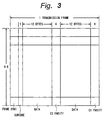
- Fig. 3 is a schematic diagram for explaining a data structure of a conventional CD.
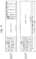
- Fig. 4 is a schematic diagram for explaining data structures of a conventional CD-ROM.
- Fig. 5 is a schematic diagram for explaining data structures in mode 2 of a conventional CD-ROM.
- Figs. 6A and 6B are schematic diagrams showing an example of a data structure of a 2-kbyte sector in the embodiment of the invention.
- Figs. 7A and 7B are schematic diagrams showing an example of a data structure of a CD-ROM sector in the embodiment of the invention.
- Fig. 8 is a schematic diagram showing another example of a data structure of a CD-ROM sector in the embodiment of the invention.
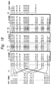
- Fig. 9 is a schematic diagram which is used for explanation of an error correction code of a block unit in the embodiment of the invention.
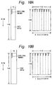
- Figs. 10A and 10B are schematic diagrams which is used for explanation of block constructions in the embodiment of the invention.
- Fig. 11 is a block diagram of an example of an encoder of the error correction code for recording data in the embodiment of the invention.
- Fig. 12 is a block diagram of an example of an decoder of the error correction code for recording data in the embodiment of the invention.
- Figs. 13A to 13C are schematic diagrams showing constructions of recording data after completion of a modulation in the embodiment of the invention.
- Fig. 1 shows an optical disc recording/reproducing system according to the invention.
- CD-ROM data which is supplied through an interface 1 is recorded onto an optical disc 2 and data read out from the optical disc 2 is outputted through the interface 1.
- a CD-ROM drive 15 and a host computer 16 are connected to the interface 1.
- the CD-ROM data is directly supplied from the drive 15 to the interface 1 or output data of the drive 15 is once inputted to the computer 16 and is supplied from the computer 16 to the interface 1.
- data there is compressed video data, compressed audio data, data for a computer, or the like.
- a recordable type (disc of a magnetooptic type or phase change type) of the DVD which is at present proposed is an example of the optical disc 2.
- the CD-ROM data to which the invention can be applied will now be described.
- the CD-ROM is a device developed from the well-known CD.
- a subcode of one byte, data of 24 bytes, and a C1 parity and a C2 parity each consisting of 4 bytes are arranged in a transmission frame (also called an EFM frame or a C1 frame).
- Each byte is converted into a code word of 14 channel bits by an EFM modulation and recorded onto the CD through coupling bits (3 channel bits).
- an inversion interval of 11T (T denotes a period of the channel bits) continues at the head of each transmission frame.
- a sync denotes a synchronization signal
- a data structure of the CD-ROM is specified on the basis of such a transmission format of the CD. Namely, in the CD-ROM, 2,352 bytes as data included in 98 frames of the period of the subcode are set to a data unit.
- mode 0 In the CD-ROM, mode 0, mode 1, and mode 2 are specified.
- a sync (12 bytes) indicative of a delimiter of the sectors and a header (4 bytes) are added commonly for those modes.
- Mode 0 relates to data in which all portions other than the sync and header are equal to "0" and it is used as dummy data.
- Fig. 4 shows data structures of one sector in mode 1 and mode 2.
- the header is constructed by address information of 3 bytes and mode information of one byte in a manner similar to the subcode of the CD.
- the user data consists of 2,048 (2 k) bytes and auxiliary data of 288 bytes are added in order to raise an error correcting ability. That is, an error detection code (4 bytes), a space (corresponding to 8 bytes), a P parity (172 bytes), and a Q parity (104 bytes) are added.
- Mode 1 is suitable for recording data such as character code, computer data, or the like in which a high reliability is required.
- Mode 2 is a mode in which the auxiliary data of 288 bytes is not added, therefore, the user data of 2,336 bytes can be recorded.
- Mode 2 is suitable for recording data such as video data or audio data whose errors can be interpolated.
- a CD-I, a CD-ROM XA, a video CD, or the like has data structures of form 1 and form 2.
- a sync of 12 bytes and a header of 4 bytes are added and mode information in the header is set to mode 2.
- a subheader of 8 bytes is added. The subheader is constructed by a final number, a channel number, a submode, and a data type each consisting of 2 bytes.
- an error detection code of 4 bytes, a P parity of 172 bytes, and a Q parity of 104 bytes are added.
- the space in mode 1 of the CD-ROM doesn't exist and an area of the user data is set to 2,048 bytes.
- a reserve area (4 bytes) is provided and the area of the user data is set to 2,324 bytes.
- the CD-ROM data of the data structure (mode 1 or mode 2 ⁇ form 1) specified so that the user data of 2 kbytes is protected by the error correction code is received from the interface 1.
- CD-ROM sector a sector structure in which the format of the CD-ROM data, particularly, an error correction code (P parity and Q parity) is preserved.
- the other is a sector structure (called a 2-kbyte sector) which is formed by the data obtained by decoding the CD-ROM data and in which 2 kbytes are set to a unit.
- the CD-ROM data is sector segmented into the CD-ROM sectors.
- the CD-ROM data is data of computer software
- the CD-ROM data is sector segmented into CD-ROM sectors.
- the CD-ROM data is sector segmented into 2-kbyte sectors. In case of the image data or music data, after the data was reproduced, it can be also interpolated. Therefore, a high reliability of the data is not so necessary.
- a data structure of the 2-kbyte sector will now be described.
- the sector having the data structure shown in Fig. 6A is called a 2-kbyte sector.
- Fig. 6B shows the data of the header in more detail. That is, the header is constructed by: 2 bytes of the error detection code (specifically, CRC) for the header; 1 byte of management information CGMS to manage a permission or an inhibition of the copy; 1 byte of a layer which discriminates a single-layer disc and a multi-layer disc and shows the number of layers included in the disc and the number of the layer in which data has been recorded; 4 bytes of an address; and 8 bytes of auxiliary data.
- a sector ID signal to identify the sector structure (2-kbyte sector or CD-ROM sector) is inserted into the auxiliary data.
- a length of one sector is equal to 2,368 bytes.
- the header is constructed by a CRC (2 bytes), copy management information CGMS, a layer, an address, and auxiliary data (4 bytes).
- the header in Fig. 7B has substantially the same information as the header shown in Fig. 6B except that the length of auxiliary data is short.
- a sector including one sector of the CD-ROM data is called a CD-ROM sector.
- a CD-ROM sector in which a sector size is equal to 2,368 bytes, as shown in Fig. 8, a format in which an error detection code (EDC) of 4 bytes is added can be also used.
- EDC error detection code
- data of 2 kbytes is included in one sector
- data of the number of bytes that is integer times as large as 128 bytes or 512 bytes can be also included in the sector.
- the length of one sector of the 2-kbyte sector and the length of the CD-ROM sector are different and there is no relation of an integer ratio between them.
- blocks of sizes which satisfy a relation between nA and mB (n and m are integers; n ⁇ m, n > m) are specified.
- the data is recorded/reproduced (namely, accessed) on a block unit basis.
- an error correcting ability can be raised.
- a coding of a first error correction code (referred to as a C1 code) is executed to 162 bytes in the vertical direction (each column) and a C1 parity of 8 bytes is formed.
- a coding of a second error correction code (referred to as a C2 code) is performed to 156 bytes in the oblique direction and a C2 parity of 14 bytes is added.
- Those error correction codings are a double coding of a convolution type.
- error correction codes other than those codes, it is also possible to use a product code, a double coding of a block completion type, an LDC (Long Distance Code), or the like. A coding by a simple error detection code can be also performed.
- FIG. 10A shows processes regarding the sector of 2,072 bytes shown in Figs. 6A and 6B .
- Fig. 10B shows processes regarding the sector of 2,368 bytes shown in Figs. 7A and 7B.
- Digital data received by the interface 1 is supplied from the interface 1 to a CD-ROM sector segmenting circuit 4 and a CD-ROM decoder 5 through a switching circuit 3.
- the sector segmenting circuit 4 is connected to one output terminal HR of the switching circuit 3 and the decoder 5 is connected to another output terminal HC.
- a decoding output of the CD-ROM decoder 5 is supplied to a 2-kbyte sector segmenting circuit 6.
- Each of the sector segmenting circuits 4 and 6 divides the received digital data every sector, adds a sector sync and a header, and executes an error detection coding.
- the sector segmenting circuit 4 converts the received data into a CD-ROM sector structure of a size of 2,368 bytes as shown in Fig. 7A.
- the sector segmenting circuit 6 converts the received data into a 2-kbyte sector structure of a size of 2,072 bytes as shown in Fig. 6A.
- the CD-ROM decoder 5 performs an error correction to one sector of the CD-ROM data and generates 2 kbytes of the user data after completion of the error correction.
- the sector segmenting circuit 4 has a construction such that one sector of the CD-ROM data is converted as it is into the CD-ROM sector without performing the error correction or a construction such that the received CD-ROM data is once decoded by the error correction code of the CD-ROM and is again converted into a data structure of the CD-ROM in a manner similar to the CD-ROM decoder 5.
- processes for decoding and coding the data of the CD-ROM are preferable. The details are disclosed in the specification of U.S.P. No. 33,462 issued again in the U.S.A. (JP-B-7-101543).
- the switching circuit 3 is controlled by a control signal which is outputted from a controller 13 connected to the interface 1.
- the interface 1 receives an instruction command which is supplied from the host computer 16 together with the CD-ROM data.
- the instruction information can be also formed in accordance with the presence or absence of errors of the received data. That is, it is also possible to construct such that the received data is once supplied to the CD-ROM decoder and in accordance with a result of the error correction in the CD-ROM decoder, when there are errors, the CD-ROM sector segmentation is performed and when there is no error, the 2-kbyte sector segmentation is performed.
- a control signal to control the switching circuit 3 is supplied to the sector segmenting circuits 4 and 6 and the control signal is inserted as a part of, for example, the auxiliary data into the header of each sector.
- a selected one of the output data of the sector segmenting circuits 4 and 6 is supplied to a block segmenting circuit 7.
- the block segmenting circuit 7 constructs a block (16,576 bytes) consisting of 7 sectors (in case of the CD-ROM sector) or 8 sectors (in case of the 2-kbyte sector) in correspondence to the sector size of the inputted data and executes a coding of the error correction code of every block as shown in Fig. 9.
- a controller 13 gives a signal to instruct a sector size to the block segmenting circuit 7.
- the error correction code differs from the error correction code which has inherently been allocated to the CD-ROM data.
- Data from the block segmenting circuit 7 is supplied to a recording processing circuit 8.
- the recording processing circuit 8 executes processes such as error correction coding, digital modulation, addition of a sync signal (frame sync), and the like.
- a signal to instruct the sector structure is supplied from the controller 3 to the recording processing circuit 8.
- Recording data from the recording processing circuit 8 is supplied to an optical pickup 10 through a driver 9 and is recorded onto the optical disc 2.
- the recording is performed by a magnetooptic recording or a phase change.
- the optical disc 2 is rotated by a spindle motor 11 at a CLV (constant linear velocity) or CAV (constant angular velocity).
- the minimum unit of the data which is recorded/reproduced by the optical pickup 10 is set to one sector mentioned above.
- the reproduction data which is read out by the optical pickup 10 is supplied to a detecting circuit 21 including an RF amplifier, a PLL circuit for clock extraction, and the like.
- An output of the detecting circuit 21 is supplied to a reproduction processing circuit 22.
- a focusing servo, a tracking servo, a control of a feeding operation (seek), a control of a laser power upon recording, and the like of the optical pickup are executed on the basis of the output of the optical pickup 10.
- the reproduction processing circuit 22 is constructed by a sync separating circuit, a digital demodulating circuit, an error correcting circuit, and the like.
- the reproduction data from the detecting circuit 21 is supplied to the sync separating circuit and the frame sync is separated.
- a clock signal synchronized with the reproduction data is formed from the separated frame sync.
- the digital demodulating circuit executes processes opposite to those of the digital modulating circuit. Data in which one symbol is returned to one byte is generated from the demodulating circuit.
- Output data of the digital demodulating circuit is supplied to the error correcting circuit and an error correction of the reproduction data is executed by the error correcting circuit.
- a block desegmenting circuit 23 is connected to the reproduction processing circuit 22.
- the reproduction data is divided every block and a decoding of the error correction code of the block is performed.
- the block desegmenting circuit 23 executes processes opposite to the processes of the block segmenting circuit 7 on the recording side.
- the block desegmenting circuit 23 outputs the data of the sector structure.
- the output data of the block desegmenting circuit 23 is distributed to output terminals HR and HC by a switching circuit 24, respectively.
- a CD-ROM sector desegmenting circuit 25 is connected to the output terminal HR.
- a 2-kbyte sector desegmenting circuit 26 is connected to the output terminal HC.
- a CD-ROM encoder 27 is connected to the sector desegmenting circuit 26. Output data of the CD-ROM sector desegmenting circuit 25 or output data of the CD-ROM encoder 27 is supplied to the interface 1.
- a sync detecting circuit 29 is connected in conjunction with the reproduction processing circuit 22.
- the sync detecting circuit 29 When the sector structure is identified by the sync pattern, the sync detecting circuit 29 generates a sector discrimination signal in correspondence to the pattern of the separated sync.
- the sector discrimination signal is supplied to the controller 13.
- a signal to control the block desegmenting circuit 23 and a signal to control the switching circuit 24 are generated from the controller 13.
- Those control signals can be also formed on the basis of the instruction command which is supplied to the interface 1 together with a read command. Further, the controller 13 can also generate instruction information on the basis of the operation of the user in the keyboard 14.
- the CD-ROM sector desegmenting circuit 25 separates and outputs the CD-ROM data of 2,352 bytes from the CD-ROM sector shown in Fig. 7A. If a high reliability is requested, after the CD-ROM data was separated, an error correction is performed by the CD-ROM decoder and the CD-ROM data is formed by the CD-ROM encoder.
- the 2-kbyte sector desegmenting circuit 26 separates the data of 2,048 bytes from the 2-kbyte sector shown in Fig. 6A.
- the CD-ROM encoder 27 uses the data of 2,048 bytes from the sector desegmenting circuit 26 as user data and forms the CD-ROM data (refer to Fig. 4) in mode 1 or the CD-ROM data (refer to Fig. 5) in mode 2 ⁇ form 1.
- the reproduction data converted into the CD-ROM data as mentioned above is transferred to the host computer 16 through the interface 1.
- Fig. 11 is a block diagram showing processes for coding of the error correction code which is performed by an encoder of the error correction code provided in the recording processing circuit 8.
- the error correction code is similar to a Cross Interleave Reed Solomon code (example of double coding of the convolution type) used in the CD.
- input symbols of 148 bytes are supplied to a C1 encoder 41.
- An output (data symbols of 148 bytes and C1 parity P of 8 bytes) of the C1 encoder 41 is supplied to a C2 encoder 43 through a group of delay circuits 42 for interleave.
- a C2 parity Q of 14 bytes is formed by the coding of a [170, 156, 15] Reed Solomon code.
- the C2 parity Q is fed back from the C2 encoder 43 to the C1 encoder 41 through a group of delay circuits 42a. Therefore, the C1 encoder 41 performs a coding of a [170, 162, 9] Reed Solomon code.
- 170 bytes (consisting of the data of 148 bytes, the C1 parity of 8 bytes, and the C2 parity of 14 bytes) from the C1 encoder 41 are extracted as output symbols through an arrangement changing circuit 44 including a delay circuit.
- the output symbols are supplied to the digital modulating circuit.
- An interleave length (also referred to as a restriction length of interleave or a depth of interleave) of the double coding of the convolution type is set to 170 frames (frame indicates a length of C1 code series and denotes two frames of the transmission frame) in correspondence to the maximum delay amount by the delay circuit.
- Fig. 12 is a block diagram showing processes of the decoder of the error correction code provided in the reproduction processing circuit 22.
- Input symbols (170 bytes) from the digital demodulating circuit are supplied to a C1 decoder 2 through an arrangement changing circuit 51.
- the arrangement changing circuit 51 executes processes opposite to those of the arrangement changing circuit 44 of the encoder.
- the C1 decoder 52 performs a decoding of a [170, 162, 9] Reed Solomon code.
- An output of the C1 decoder 52 is supplied to a C2 decoder 54 through a group of delay circuits 53.
- the C2 decoder 54 performs a decoding of a [170, 156, 15] Reed Solomon code. Further, a decoding output of the C2 decoder 54 is supplied to a C1 decoder 56 through a group of delay circuits 55 for deinterleave. Output symbols of 148 bytes which were error corrected by the processes of the C1 decoding, C2 decoding, and C1 decoding as mentioned above are extracted.
- a sector sync S3 or a C1 sync S2 of 32 channel bits is added to modulation data symbols of the former half.
- An additional sync S1 of 32 channel bits is added to modulation data symbols of the latter half and one transmission frame is similarly constructed.
- the sector sync S3 is added to the head transmission frame among the 28 transmission frames.
- Recording data corresponding to one sector of the CD-ROM sector is shown in Fig. 13B.
- a sector sync S4 is added to the head transmission frame among those transmission frames.
- One method of adding the block sync on a block unit basis is, further, shown in Fig. 13C.
- one block is constructed by eight 2-kbyte sectors or seven CD-ROM sectors.
- a block sync S5 is added in place of the sector sync S3 or S4.
- the sector sync S3 or S4 is added.
- the block sync S5 can be also added independent of the sector sync.
- the controller 13 can identify the sector structure from an output of the sync detecting circuit 29 (refer to Fig. 1).
- the sector structure can be also identified on a block unit basis by the bit pattern of the block sync S5 in place of the sector sync.
- the data when the CD-ROM data is received and a high reliability is requested, the data is sector segmented as a CD-ROM sector and the data of the CD-ROM sector is recorded onto the optical disc 2 and reproduced from the optical disc 2.
- the received CD-ROM data is sector segmented as a 2-kbyte sector and the recording/reproduction are executed.
- the data which is inputted/outputted to/from the interface 1 has a format of the CD-ROM data. Two kinds of recording/reproducing operations can be carried out in accordance with the reliability.
- Fig. 2 shows a construction of a recording/reproducing system of another embodiment of the invention.
- a construction in a range from the block segmenting circuit 7 to the optical pickup 10 of the recording system and a construction in a range from the optical pickup 10 to the block desegmenting circuit 23 of the reproducing system are the same as those of the foregoing embodiment. Therefore, their descriptions are omitted.
- digital data divided every 2 kbytes is supplied to the interface 1.
- the input data is distributed to the terminals HR and HC by the switching circuit 3.
- a CD-ROM encoder 12 is connected to the terminal HR that is selected when importance is attached to the high reliability.
- the CD-ROM sector segmenting circuit 4 is connected to the encoder 12.
- the 2-kbyte sector segmenting circuit 6 is connected to the terminal HC that is selected in case of increasing the recording capacity.
- the CD-ROM encoder 12 forms the CD-ROM data of the format of mode 1 or mode 2 ⁇ form 1 in which 2 kbytes of the input data are set to the user data.
- An output of the CD-ROM encoder 12 is supplied to the CD-ROM sector segmenting circuit 4 and a CD-ROM sector shown in Fig. 7A is formed.
- the 2-kbyte sector segmenting circuit 6 forms a 2-kbyte sector shown in Fig. 6A.
- the data converted into the structure of the CD-ROM sector or 2-kbyte sector is supplied to the block segmenting circuit 7.
- the switching circuit 24 which is connected to the block desegmenting circuit 23 is controlled by a control signal from the controller 13 in a manner similar to the switching circuit 3 on the recording side.
- a CD-ROM decoder 28 is connected to the terminal HR of the switching circuit 24 through the CD-ROM sector desegmenting circuit 25.
- the 2-kbyte sector desegmenting circuit 26 is connected to the terminal HC of the switching circuit 24.
- the CD-ROM sector desegmenting circuit 25 and CD-ROM decoder 28 are provided in correspondence to that the CD-ROM encoder 12 and CD-ROM sector segmenting circuit 4 are provided.
- the 2-kbyte sector desegmenting circuit 26 is provided in correspondence to the 2-kbyte sector segmenting circuit 6 on the recording side.
- the data of the 2-kbyte unit when the data of the 2-kbyte unit is received and the high reliability is requested, after the data was coded into the CD-ROM data, it is sector segmented as CD-ROM sectors, and the data of the CD-ROM sector is recorded onto the optical disc 2 and is reproduced from the optical disc 2.
- the received 2-kbyte data when importance is attached to the recording capacity rather than the reliability, the received 2-kbyte data is sector segmented as 2-kbyte sectors and the recording/reproduction are executed.
- the data that is inputted/outputted to/from the interface 1 is the data in which 2 kbytes are set to a unit. In this manner, two kinds of recording/reproducing operations can be performed in accordance with the reliability.
- optical disc has been descried above as an example, the invention can be similarly applied to a hard disc, a flexible disk (FD), further, a semiconductor memory, and a tape-shaped recording medium.
- the recording process when recording the CD-ROM data from the CD-ROM drive or the data of the 2-kbyte unit from the hard disc drive, the recording process can be switched in accordance with the reliability that is required, the recording capacity that is required, or the like. Therefore, when the digital data is recorded, a flexibility can be provided. According to the invention, any one of the data of the 2-kbyte unit or the CD-ROM data can be used as data that is inputted/outputted.
Landscapes
- Engineering & Computer Science (AREA)
- Signal Processing (AREA)
- Multimedia (AREA)
- Signal Processing For Digital Recording And Reproducing (AREA)
Applications Claiming Priority (3)
| Application Number | Priority Date | Filing Date | Title |
|---|---|---|---|
| JP23911995 | 1995-08-24 | ||
| JP239119/95 | 1995-08-24 | ||
| PCT/JP1996/002344 WO1997008695A1 (fr) | 1995-08-24 | 1996-08-22 | Appareil d'enregistrement de donnees, procede et appareil de reproduction de donnees |
Publications (2)
| Publication Number | Publication Date |
|---|---|
| EP0807930A1 true EP0807930A1 (fr) | 1997-11-19 |
| EP0807930A4 EP0807930A4 (fr) | 2002-04-10 |
Family
ID=17040080
Family Applications (1)
| Application Number | Title | Priority Date | Filing Date |
|---|---|---|---|
| EP96927873A Ceased EP0807930A4 (fr) | 1995-08-24 | 1996-08-22 | Appareil d'enregistrement de donnees, procede et appareil de reproduction de donnees |
Country Status (6)
| Country | Link |
|---|---|
| US (1) | US6226247B1 (fr) |
| EP (1) | EP0807930A4 (fr) |
| JP (1) | JP3735865B2 (fr) |
| KR (1) | KR100273080B1 (fr) |
| CN (1) | CN1104721C (fr) |
| WO (1) | WO1997008695A1 (fr) |
Cited By (1)
| Publication number | Priority date | Publication date | Assignee | Title |
|---|---|---|---|---|
| WO2002099803A1 (fr) * | 2001-06-01 | 2002-12-12 | Dataplay, Inc. | Format de bloc de code correcteur d'erreurs |
Families Citing this family (9)
| Publication number | Priority date | Publication date | Assignee | Title |
|---|---|---|---|---|
| US6687826B1 (en) * | 1997-12-29 | 2004-02-03 | Sony Corporation | Optical disc and method of recording data into same |
| US6553086B1 (en) * | 1998-10-02 | 2003-04-22 | Lg Electronics, Inc. | Method and apparatus for recording time information for digital data streams |
| JP4059410B2 (ja) * | 1998-10-07 | 2008-03-12 | 株式会社バンダイナムコゲームス | ゲーム装置及び情報記憶媒体 |
| KR100326144B1 (ko) * | 1999-02-09 | 2002-03-13 | 구자홍 | 기록 디지털 데이터 스트림의 탐색정보 생성방법 및 이를이용한 탐색방법과, 그 장치 |
| PL345894A1 (en) * | 1999-06-10 | 2002-01-14 | Koninkl Philips Electronics Nv | Error correction encoding a data stream of information |
| JP2001043616A (ja) | 1999-07-30 | 2001-02-16 | Sharp Corp | 記録方法、記録媒体及び記録装置 |
| TWI234160B (en) * | 1999-10-05 | 2005-06-11 | Sanyo Electric Co | Buffering method for digital data, and CD-ROM decoder |
| JP3297668B2 (ja) * | 2000-04-26 | 2002-07-02 | 松下電器産業株式会社 | 符号/復号化装置及び符号/復号化方法 |
| EP1421586A1 (fr) * | 2001-08-24 | 2004-05-26 | Koninklijke Philips Electronics N.V. | Appareil d'enregistrement pour enregistrer les donnees optiques sur des disques a lecture optique |
Citations (2)
| Publication number | Priority date | Publication date | Assignee | Title |
|---|---|---|---|---|
| US4680764A (en) * | 1984-03-24 | 1987-07-14 | Sony Corporation | Method and apparatus for transmitting digital data |
| US4802169A (en) * | 1986-02-24 | 1989-01-31 | Sony Corporation | Method of and device for storing and reading digital information at option protected or not by an error correcting code |
Family Cites Families (13)
| Publication number | Priority date | Publication date | Assignee | Title |
|---|---|---|---|---|
| JPH03119574A (ja) * | 1989-10-02 | 1991-05-21 | Sony Corp | 記録情報発生方法 |
| JPH03176869A (ja) * | 1989-12-05 | 1991-07-31 | Matsushita Electric Ind Co Ltd | ディジタル信号記録方法 |
| JP2712743B2 (ja) * | 1990-04-18 | 1998-02-16 | 松下電器産業株式会社 | ディスク再生装置 |
| JPH0652630A (ja) | 1991-03-28 | 1994-02-25 | Sony Corp | データ記録方法 |
| JP3256981B2 (ja) | 1991-04-05 | 2002-02-18 | ソニー株式会社 | データ記録方法 |
| JP2670398B2 (ja) * | 1991-09-30 | 1997-10-29 | 松下電器産業株式会社 | 符号化信号複製装置 |
| JP2989338B2 (ja) * | 1991-10-03 | 1999-12-13 | 三洋電機株式会社 | ダビング方法 |
| JPH06111459A (ja) * | 1992-09-24 | 1994-04-22 | Sony Corp | 光デイスク装置及びデータ記録方法 |
| JP3511646B2 (ja) * | 1993-08-31 | 2004-03-29 | ソニー株式会社 | 光ディスクデータ記録装置及び光ディスクデータ記録方法 |
| TW316976B (fr) | 1995-05-16 | 1997-10-01 | Sony Co Ltd | |
| TW301740B (fr) | 1995-05-31 | 1997-04-01 | Sony Co Ltd | |
| MY112755A (en) | 1995-06-06 | 2001-08-30 | Sony Corp | Information data reproducing system, reproducing apparatus, reproducing method, data forming apparatus and data record medium |
| TW307862B (fr) | 1995-06-20 | 1997-06-11 | Sony Co Ltd |
-
1996
- 1996-08-22 JP JP51010497A patent/JP3735865B2/ja not_active Expired - Fee Related
- 1996-08-22 KR KR1019970702828A patent/KR100273080B1/ko not_active IP Right Cessation
- 1996-08-22 CN CN96190958A patent/CN1104721C/zh not_active Expired - Fee Related
- 1996-08-22 WO PCT/JP1996/002344 patent/WO1997008695A1/fr active IP Right Grant
- 1996-08-22 US US08/817,781 patent/US6226247B1/en not_active Expired - Fee Related
- 1996-08-22 EP EP96927873A patent/EP0807930A4/fr not_active Ceased
Patent Citations (2)
| Publication number | Priority date | Publication date | Assignee | Title |
|---|---|---|---|---|
| US4680764A (en) * | 1984-03-24 | 1987-07-14 | Sony Corporation | Method and apparatus for transmitting digital data |
| US4802169A (en) * | 1986-02-24 | 1989-01-31 | Sony Corporation | Method of and device for storing and reading digital information at option protected or not by an error correcting code |
Non-Patent Citations (1)
| Title |
|---|
| See also references of WO9708695A1 * |
Cited By (2)
| Publication number | Priority date | Publication date | Assignee | Title |
|---|---|---|---|---|
| WO2002099803A1 (fr) * | 2001-06-01 | 2002-12-12 | Dataplay, Inc. | Format de bloc de code correcteur d'erreurs |
| US6910174B2 (en) | 2001-06-01 | 2005-06-21 | Dphi Acquisitions, Inc. | Error correction code block format |
Also Published As
| Publication number | Publication date |
|---|---|
| CN1164919A (zh) | 1997-11-12 |
| US6226247B1 (en) | 2001-05-01 |
| KR970707539A (ko) | 1997-12-01 |
| CN1104721C (zh) | 2003-04-02 |
| JP3735865B2 (ja) | 2006-01-18 |
| KR100273080B1 (ko) | 2000-12-01 |
| EP0807930A4 (fr) | 2002-04-10 |
| WO1997008695A1 (fr) | 1997-03-06 |
Similar Documents
| Publication | Publication Date | Title |
|---|---|---|
| US5694381A (en) | Information data reproducing system, reproducing apparatus, reproducing method, data forming apparatus, and data record medium | |
| US6215750B1 (en) | Data recording/reproducing apparatus and method corresponding to a plurality of data formats, and data recording medium | |
| KR100436943B1 (ko) | 데이타기록및재생장치 | |
| US5896355A (en) | Data recording/reproducing apparatus corresponding to a plurality of error correcting system and a data recording medium | |
| EP0745994B1 (fr) | Appareil d'enregistrement/de reproduction de données, méthode correspondante, et support d'enregistrement de données | |
| US6661758B2 (en) | High speed data recording and/or reproducing method and apparatus with increased sector access speed | |
| US6226247B1 (en) | Data recording apparatus that identifies the type of data in each block of data | |
| US6118754A (en) | Data recording/reproducing apparatus and method corresponding to a plurality of data formats, and data recording medium | |
| JP3509394B2 (ja) | 情報データ再生システム、再生装置、再生方法およびコピー禁止方法 | |
| JP3557729B2 (ja) | データ記録/再生装置および方法、並びにディスク状記録媒体 | |
| JP3496345B2 (ja) | データ記録装置および方法 | |
| JP3557728B2 (ja) | データ記録/再生装置および方法、並びにディスク状記録媒体 | |
| AU765318B2 (en) | Method for recording/reproducing data with a plurality of sector formats on record medium and apparatus thereof | |
| JP3775412B2 (ja) | データ記録媒体及び情報データ書込装置 | |
| JPH0935416A (ja) | データ記録/再生装置および方法、並びにデータ記録媒体 | |
| JP2006196176A (ja) | データ記録/再生装置および方法、並びにディスク状記録媒体 | |
| JPH08329616A (ja) | データ記録/再生装置および方法、並びにデータ記録媒体 | |
| JPH0963200A (ja) | データ記録/再生装置および方法、並びにデータ記録媒体 |
Legal Events
| Date | Code | Title | Description |
|---|---|---|---|
| PUAI | Public reference made under article 153(3) epc to a published international application that has entered the european phase |
Free format text: ORIGINAL CODE: 0009012 |
|
| 17P | Request for examination filed |
Effective date: 19970418 |
|
| AK | Designated contracting states |
Kind code of ref document: A1 Designated state(s): DE FR GB NL |
|
| A4 | Supplementary search report drawn up and despatched |
Effective date: 20020225 |
|
| AK | Designated contracting states |
Kind code of ref document: A4 Designated state(s): DE FR GB NL |
|
| RIC1 | Information provided on ipc code assigned before grant |
Free format text: 7G 11B 19/02 A, 7G 11B 20/12 B, 7G 11B 20/18 B |
|
| 17Q | First examination report despatched |
Effective date: 20021021 |
|
| STAA | Information on the status of an ep patent application or granted ep patent |
Free format text: STATUS: THE APPLICATION HAS BEEN REFUSED |
|
| 18R | Application refused |
Effective date: 20081002 |