EP0807540A2 - Roue à pivot - Google Patents
Roue à pivot Download PDFInfo
- Publication number
- EP0807540A2 EP0807540A2 EP97107539A EP97107539A EP0807540A2 EP 0807540 A2 EP0807540 A2 EP 0807540A2 EP 97107539 A EP97107539 A EP 97107539A EP 97107539 A EP97107539 A EP 97107539A EP 0807540 A2 EP0807540 A2 EP 0807540A2
- Authority
- EP
- European Patent Office
- Prior art keywords
- trailing wheel
- spring
- pivot pin
- stop part
- wheel according
- Prior art date
- Legal status (The legal status is an assumption and is not a legal conclusion. Google has not performed a legal analysis and makes no representation as to the accuracy of the status listed.)
- Withdrawn
Links
Images
Classifications
-
- B—PERFORMING OPERATIONS; TRANSPORTING
- B60—VEHICLES IN GENERAL
- B60B—VEHICLE WHEELS; CASTORS; AXLES FOR WHEELS OR CASTORS; INCREASING WHEEL ADHESION
- B60B33/00—Castors in general; Anti-clogging castors
- B60B33/02—Castors in general; Anti-clogging castors with disengageable swivel action, i.e. comprising a swivel locking mechanism
- B60B33/023—Castors in general; Anti-clogging castors with disengageable swivel action, i.e. comprising a swivel locking mechanism by using friction
-
- B—PERFORMING OPERATIONS; TRANSPORTING
- B60—VEHICLES IN GENERAL
- B60B—VEHICLE WHEELS; CASTORS; AXLES FOR WHEELS OR CASTORS; INCREASING WHEEL ADHESION
- B60B33/00—Castors in general; Anti-clogging castors
- B60B33/0036—Castors in general; Anti-clogging castors characterised by type of wheels
- B60B33/0039—Single wheels
-
- B—PERFORMING OPERATIONS; TRANSPORTING
- B60—VEHICLES IN GENERAL
- B60B—VEHICLE WHEELS; CASTORS; AXLES FOR WHEELS OR CASTORS; INCREASING WHEEL ADHESION
- B60B33/00—Castors in general; Anti-clogging castors
- B60B33/0047—Castors in general; Anti-clogging castors characterised by details of the rolling axle
- B60B33/0057—Castors in general; Anti-clogging castors characterised by details of the rolling axle the rolling axle being offset from swivel axis
-
- B—PERFORMING OPERATIONS; TRANSPORTING
- B60—VEHICLES IN GENERAL
- B60B—VEHICLE WHEELS; CASTORS; AXLES FOR WHEELS OR CASTORS; INCREASING WHEEL ADHESION
- B60B33/00—Castors in general; Anti-clogging castors
- B60B33/006—Castors in general; Anti-clogging castors characterised by details of the swivel mechanism
- B60B33/0065—Castors in general; Anti-clogging castors characterised by details of the swivel mechanism characterised by details of the swivel axis
- B60B33/0068—Castors in general; Anti-clogging castors characterised by details of the swivel mechanism characterised by details of the swivel axis the swivel axis being vertical
-
- B—PERFORMING OPERATIONS; TRANSPORTING
- B60—VEHICLES IN GENERAL
- B60B—VEHICLE WHEELS; CASTORS; AXLES FOR WHEELS OR CASTORS; INCREASING WHEEL ADHESION
- B60B33/00—Castors in general; Anti-clogging castors
- B60B33/04—Castors in general; Anti-clogging castors adjustable, e.g. in height; linearly shifting castors
-
- B—PERFORMING OPERATIONS; TRANSPORTING
- B60—VEHICLES IN GENERAL
- B60Y—INDEXING SCHEME RELATING TO ASPECTS CROSS-CUTTING VEHICLE TECHNOLOGY
- B60Y2200/00—Type of vehicle
- B60Y2200/20—Off-Road Vehicles
- B60Y2200/22—Agricultural vehicles
- B60Y2200/223—Ridable lawn mowers
Definitions
- the invention relates to a trailing wheel with a vertical pivot pin which is rotatably arranged in an opening provided in a fastening part.
- This known trailing wheel (US-A-4 854 112) is one of the support wheels for a cutting unit of a lawnmower. As is known, such wheels also pivot when the mower changes its direction of travel, for example when cornering. Since the trailing wheels then swivel, damage to the lawn is rather rare. On the other hand, such trailing wheels have the characteristic that they tend to spin when they are lifted off the ground. Of course, when using these trailing wheels on cutting units, it often happens that the wheels have no contact with the ground, for example when the cutting unit has been swung up. Then rotating trailing wheels cause annoying noises. So-called clamping caps have already been proposed to reduce the risk of spinning.
- the object to be achieved with the invention is seen in at least reducing the risk of gyration in the case of oscillating trailing wheels, which is why, according to the invention, a spring-loaded stop part is initially provided, which against the pivot pin or against the inner circumference of the Opening can be brought to the system.
- the stop part acts like a running brake, which brings a rotating trailing wheel to a standstill immediately, if there should ever be a rotation.
- the stop part can be brought into abutment against a latching surface, the stop part and latching surface being rotatable relative to one another and provided on the fastening part and pivot pin.
- the locking surface determines the predetermined position in which the trailing wheel is held. The locking surface is designed such that the stop part forces the trailing wheel into the predetermined position when it comes into contact with the locking surface.
- the latching surface can be formed in a simple manner in that the jacket surface of the pivot pin is provided with a flattened surface against which the stop part can be brought into abutment, wherein the stop part can consist of a spring-loaded ball, which in the assembled state together with the spring in one is provided in the mounting part machined hole and presses against the pivot pin.
- the opening receiving the pivot pin is provided with a recessed section, which then forms the latching surface, against which the stop part bears.
- the recessed section is practically formed as a recess with ramp-shaped edges which force the pivot pin into the predetermined position, the pivot pin being provided with a radial bore which receives the stop part consisting of a spring-loaded ball together with the spring.
- the trailing wheel can be provided on a mower of a lawnmower, because the advantages of the trailing wheel according to the invention have a particularly positive effect on lawnmowers.
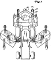
- a large-area lawn mower with sickle mowers is shown schematically.
- Such lawn mowers have a relatively large working width, and the outer side mowers can be folded up into a transport position.
- the preferred exemplary embodiment is less concerned with the large-area lawn mower and more with a pendulum or trailing wheel arrangement 10 for the individual mower units, whether they are attached to the side or in front of the vehicle.
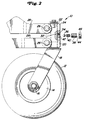
- the tire running on the ground is designated by 12, a hub-rim part receiving the tire by 14 and the wheel axle by 16.
- a fork 18 engages, which in the usual way with the vertical bolt or vertical Swivel pin 20 is provided.
- the vertical bolt 20 is rotatable in an opening 22 which is provided in a fastening part 24.
- the fastening part 24 in turn is connected via screws 26 to brackets 28, which create a four-bar linkage between the fastening part 24 and a mower housing 30.
- a mechanism which prevents the pendulum wheel 12 from rotating when it is lifted off the ground.
- This mechanism essentially holds the pendulum wheel in its forward-facing position.
- the vertical shaft 20 is round in cross section over almost its entire length.
- the round cross section is designated by 32, with, as can be seen from FIGS. 2 to 5, a flattening 34 being provided in a certain area.
- a stop part or a ball 36 is arranged in a threaded part 38 and is pressed against the vertical shaft 20 via a pressure part, such as a pressure spring 40.
- the threaded part 38 can be screwed into a threaded bore 42 provided in the fastening part 24.
- the threaded part 38 is equipped with a central bore 44 which receives the spring 40 and partially the ball 36. At the end remote from the ball, the central bore can be closed by a nut 46 and thus prevents the ball and spring from falling out in the assembled state.
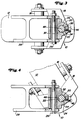
- the pendulum wheel 12 rolls on the floor surface or has contact with it. If the lawnmower makes a curve, the pendulum wheel pivots about its vertical axis so that the tire 12 remains in contact with the ground without erasing or injuring the turf.
- the vertical shaft 20 rotates in the opening 22 in the fastening part 24.
- the vertical shaft 20 rotates from its position shown in FIGS. 2 and 3, in which the flat 34 is oriented towards the front is.
- the flat 34 is initially rotated, the ball 36 is pushed into the central bore 44 of the threaded part in the direction of the nut 46, the spring 40 being compressed.
- the pendulum wheel can pivot through a large range of motion when cornering, with the tire 12 maintaining its contact with the ground.
- the pendulum wheel is also prevented from rotating, since the spring mechanism wants to hold the vertical shaft in the forwardly oriented position according to FIG. 3.
- a gyroscope can occur when the pendulum wheel is lifted off the ground, for example when swiveling up or lifting a mower. In such a case, forces can occur that rotate or spin the pendulum wheel. If the vertical shaft begins to rotate with the mower raised, then it will eventually assume the position shown in FIG. 5, for example if it has been rotated somewhat from the position shown in FIG. 3. In the position according to FIG. 5, the flattened portion 34 presses the ball 36 outwards, the compression spring 40 being slightly pressed together.
- the spring will exert a counterforce on the ball in the direction of the surface of the vertical shaft, specifically in the direction of arrow A, that is to say perpendicular to the flattened portion 34 the central axis 48 of the vertical shaft 20 is directed, a power arm 50 is created so that the vertical shaft is rotated back into its position according to FIG. 3. In the position according to FIG. 3, the force A is then directed onto the central axis 48 and the vertical shaft is held in this position.
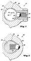
- FIG. 6 A further exemplary embodiment 52 is shown in FIG. 6.
- the spring 40 and part of the ball 36 are arranged in a bore in the vertical shaft as shown in FIG. 6.
- the ball 36 is thus pressed outwards by the spring 40 against the inner circumference 54 of the bore in the fastening part 24 receiving the vertical shaft of the pendulum wheel.
- this bore is essentially round, the round section being designated by 58.
- the round section is interrupted by a recessed section 60 which has ramp-like sides so that the ball can also emerge again. If the mower now makes a turn, then the pendulum wheel swivels again, the vertical shaft of which rotates. The ball is pressed against the action of the spring 40 from the recessed section 60.
- the spring remains compressed as long as the ball 36 bears against the round section 58.
- the force then acting against the inner circumference is so great that gyro is prevented. Should a gyroscope nevertheless occur, the ball comes back into the recessed area 60, where the spring is relaxed and compressed again.
- the compression absorbs energy, which contributes to the pendulum wheel coming to a standstill.
- the pendulum wheel is returned to its forward-facing position and also held there. If the vertical shaft rotates somewhat from its position according to FIG. 6, the ball is pressed against the spring when the side edges of the recessed section 60 press the ball inwards. The spring naturally creates a counter pressure that pushes the ball outwards. As a result of the side edges of the recessed section, a direction of force arises which does not run through the central axis of the vertical shaft and thus a force arm which rotates the vertical shaft back into its position according to FIG. 6. 6, the direction of force again runs through the central axis, so that the pendulum wheel can be held in this position.
Landscapes
- Engineering & Computer Science (AREA)
- Mechanical Engineering (AREA)
- Harvester Elements (AREA)
- Motorcycle And Bicycle Frame (AREA)
Applications Claiming Priority (2)
| Application Number | Priority Date | Filing Date | Title |
|---|---|---|---|
| US645365 | 1991-01-24 | ||
| US08/645,365 US5727285A (en) | 1996-05-13 | 1996-05-13 | Caster wheel biasing mechanism |
Publications (2)
| Publication Number | Publication Date |
|---|---|
| EP0807540A2 true EP0807540A2 (fr) | 1997-11-19 |
| EP0807540A3 EP0807540A3 (fr) | 1999-04-28 |
Family
ID=24588713
Family Applications (1)
| Application Number | Title | Priority Date | Filing Date |
|---|---|---|---|
| EP97107539A Withdrawn EP0807540A3 (fr) | 1996-05-13 | 1997-05-07 | Roue à pivot |
Country Status (3)
| Country | Link |
|---|---|
| US (1) | US5727285A (fr) |
| EP (1) | EP0807540A3 (fr) |
| CA (1) | CA2194596A1 (fr) |
Families Citing this family (21)
| Publication number | Priority date | Publication date | Assignee | Title |
|---|---|---|---|---|
| US5943735A (en) * | 1995-01-16 | 1999-08-31 | Flexello Limited | Shopping trolley, a castor for a shopping trolley and a kit of parts for fitting to such a castor |
| US6115882A (en) * | 1997-01-22 | 2000-09-12 | United Auto Systems Inc. | Caster with a shaped stem |
| US6212733B1 (en) * | 1999-08-16 | 2001-04-10 | Link Treasure Limited | Hub and wheel assembly with automatic moving direction adjustment mechanism |
| US6402166B1 (en) * | 2000-09-19 | 2002-06-11 | Ping-Jan Chiu | Locking device for limiting swiveling movement of a front wheel of a stroller |
| US6745873B1 (en) * | 2003-01-29 | 2004-06-08 | Hsi-Yuan Shawn Chen | Braking device for an exercising cycle |
| US20040168283A1 (en) * | 2003-02-28 | 2004-09-02 | Branham Tillman Wade | Controlled caster wheel |
| ES2253982B1 (es) * | 2004-05-14 | 2007-08-01 | Jose Mani Molins | Dispositivo auxiliar para el desplazamiento de camillas y similares. |
| NL1029369C2 (nl) * | 2005-06-29 | 2007-01-02 | Wellco Mobility Oldenzaal B V | Zwenkwielsamenstel en van een dergelijk samenstel voorzien voertuig. |
| EP1792750A1 (fr) * | 2005-12-05 | 2007-06-06 | Invacare International Sàrl | Dispositif de support de roue amovible pour chaise roulante |
| US20080148514A1 (en) * | 2006-12-20 | 2008-06-26 | Hancock Garry W | Direction stabilized compact swivel caster |
| US20080209673A1 (en) * | 2007-02-23 | 2008-09-04 | Cooper Rory A | Caster and system for mobile device |
| US8490242B2 (en) * | 2007-02-23 | 2013-07-23 | Universit Of Pittsburgh—Of the Commonwealth System of Higher Education | Mobile caster |
| US20090205164A1 (en) * | 2008-02-19 | 2009-08-20 | Larson Albert W | Castor Wheel Assembly |
| US7574850B1 (en) * | 2008-06-10 | 2009-08-18 | Deere & Company | Caster wheel locking system for walk-behind mower |
| US20090309331A1 (en) * | 2008-06-13 | 2009-12-17 | Harold James Ryan | Trailer apparatus including adjustable wheel assemblies |
| US8276240B2 (en) * | 2008-09-03 | 2012-10-02 | Roman Ritachka | Door mounted finger safety device |
| US8235419B1 (en) | 2009-04-10 | 2012-08-07 | Peter Anthony Giarrusso | Lateral stability system for a vehicle |
| US20110314635A1 (en) * | 2010-06-28 | 2011-12-29 | Yuan Deng Metals Industrial Co., Ltd. | Hinge |
| US8875855B2 (en) | 2012-02-24 | 2014-11-04 | Travelpro International Inc. | Wheeled luggage case |
| BE1021113B1 (nl) * | 2012-10-01 | 2015-12-18 | Cnh Industrial Belgium Nv | Zwenkwielgeheel van een opraper voor een landbouwmachine |
| JP7404538B2 (ja) * | 2019-12-16 | 2023-12-25 | ワンダーランド スイツァーランド アーゲー | 小児用キャリアのホイールのために適合された制振装置 |
Family Cites Families (12)
| Publication number | Priority date | Publication date | Assignee | Title |
|---|---|---|---|---|
| US2583858A (en) * | 1949-12-10 | 1952-01-29 | Jarvis & Jarvis Inc | Automatic swivel locking caster |
| US2960717A (en) * | 1957-09-03 | 1960-11-22 | Aerol Co Inc | Caster swivel control device |
| US3390486A (en) * | 1966-01-24 | 1968-07-02 | Herbert J. Walters | Pivoting shower door |
| US3699609A (en) * | 1971-04-12 | 1972-10-24 | William L Spatz | Spring loaded caster for shop tools, bar stools and the like |
| US3851354A (en) * | 1972-10-11 | 1974-12-03 | Amerock Corp | Self-closing butt hinge |
| DE2422154A1 (de) * | 1974-05-08 | 1975-11-27 | Schulte Soehne Kg A | Lenkrolle fuer geraete, moebel u.dgl. insbesondere krankenbetten |
| DE3303822A1 (de) * | 1983-02-04 | 1984-08-09 | Film-Geräte-Verleih Schmidle & Fitz, 8000 München | Stuetzradanordnung fuer einen kamerawagen |
| JPS6025803A (ja) * | 1983-07-22 | 1985-02-08 | Kassai Inc | キヤスタ |
| CA1284258C (fr) * | 1987-07-17 | 1991-05-21 | Darnell Inc. | Montage clavete de galet verrouillable sur pivot |
| US4942726A (en) * | 1987-08-28 | 1990-07-24 | Deere & Company | Mechanism and method for converting a fixed wheel walk-behind mower to a caster wheel walk-behind mower and vice versa |
| US4854112A (en) * | 1987-09-04 | 1989-08-08 | The Toro Company | Turf maintenance apparatus |
| CA2062630C (fr) * | 1992-01-13 | 1995-06-13 | Allen Riblett | Charniere a cliquet |
-
1996
- 1996-05-13 US US08/645,365 patent/US5727285A/en not_active Expired - Fee Related
-
1997
- 1997-01-07 CA CA002194596A patent/CA2194596A1/fr not_active Abandoned
- 1997-05-07 EP EP97107539A patent/EP0807540A3/fr not_active Withdrawn
Also Published As
| Publication number | Publication date |
|---|---|
| EP0807540A3 (fr) | 1999-04-28 |
| CA2194596A1 (fr) | 1997-11-14 |
| US5727285A (en) | 1998-03-17 |
Similar Documents
| Publication | Publication Date | Title |
|---|---|---|
| EP0807540A2 (fr) | Roue à pivot | |
| DE3732664C1 (de) | Schleppfahrzeug fuer Flugzeuge - Lenkergesteuerte Hubschaufel | |
| EP0518168B1 (fr) | Dispositif de direction d'un véhicule, en particulier tracteur de jardin ou tondeuse de gazon | |
| DE68906956T2 (de) | Vorrichtung zum Einstellen der Länge von Radaufhängungsarmen von Kraftfahrzeugen. | |
| DE2702743C2 (de) | Heuwerbungsmaschine zum Zetten/Wenden und Schwadlegen mit einem oder mehreren rotationsgetriebenen Rechrädern | |
| EP0467181A1 (fr) | Transmission hydrostatique pour un véhicule avec freins sur roues | |
| DE102017214963A1 (de) | Zentralgelenk für einen Dreipunktlenker | |
| EP3360405A1 (fr) | Tête de coupe pour une débroussailleuse | |
| EP1863694A2 (fr) | Unite a roue pivotante et chaise roulante comprenant une unite a roue pivotante | |
| DE3021605A1 (de) | Heuwerbungsmaschine zum schwaden, wenden und zetten | |
| DE69307127T2 (de) | Heuwendemaschine | |
| DE69403511T2 (de) | Heuwerbungsmaschine | |
| DE2146655A1 (de) | Heuerntemaschine | |
| DE1507341B2 (de) | Schleppergezogene heuwerbungsmaschine | |
| DE102010012666B4 (de) | Aufsitzmäher mit Höhenverstellung | |
| EP1817953B1 (fr) | Appareil d'entretien de la pelouse, du jardin ou du terrain et dispositif de réglage en hauteur | |
| DE2719797C2 (de) | Heuwerbungsmaschine zum wahlweisen Wenden/Zetten oder Schwadlegen mit wenigstens zwei rotierend angetriebenen Rechrädern | |
| DE2904244C2 (fr) | ||
| EP0033936B2 (fr) | Serrure à partie pivotante pour un véhicule, en particulier une bicyclette | |
| DE19741742C2 (de) | Gabelhubwagen mit Stützrad | |
| DE20317770U1 (de) | Vorrichtung zur Verstellung der Sitzposition eines Sattels bei einem Fahrzeug | |
| DE9414597U1 (de) | Gezogene Mähmaschine | |
| DE2850215A1 (de) | Schnitthoeheneinstellvorrichtung fuer spindelmaeher | |
| DE2554273A1 (de) | Pendelstuetzrad fuer drehpfluege | |
| DE3707856C2 (de) | Anbaudrehpflug |
Legal Events
| Date | Code | Title | Description |
|---|---|---|---|
| PUAI | Public reference made under article 153(3) epc to a published international application that has entered the european phase |
Free format text: ORIGINAL CODE: 0009012 |
|
| AK | Designated contracting states |
Kind code of ref document: A2 Designated state(s): DE FR GB IE IT |
|
| PUAL | Search report despatched |
Free format text: ORIGINAL CODE: 0009013 |
|
| AK | Designated contracting states |
Kind code of ref document: A3 Designated state(s): DE FR GB IE IT |
|
| STAA | Information on the status of an ep patent application or granted ep patent |
Free format text: STATUS: THE APPLICATION IS DEEMED TO BE WITHDRAWN |
|
| 18D | Application deemed to be withdrawn |
Effective date: 19991201 |