EP0807540A2 - Castor - Google Patents
Castor Download PDFInfo
- Publication number
- EP0807540A2 EP0807540A2 EP97107539A EP97107539A EP0807540A2 EP 0807540 A2 EP0807540 A2 EP 0807540A2 EP 97107539 A EP97107539 A EP 97107539A EP 97107539 A EP97107539 A EP 97107539A EP 0807540 A2 EP0807540 A2 EP 0807540A2
- Authority
- EP
- European Patent Office
- Prior art keywords
- trailing wheel
- spring
- pivot pin
- stop part
- wheel according
- Prior art date
- Legal status (The legal status is an assumption and is not a legal conclusion. Google has not performed a legal analysis and makes no representation as to the accuracy of the status listed.)
- Withdrawn
Links
Images
Classifications
-
- B—PERFORMING OPERATIONS; TRANSPORTING
- B60—VEHICLES IN GENERAL
- B60B—VEHICLE WHEELS; CASTORS; AXLES FOR WHEELS OR CASTORS; INCREASING WHEEL ADHESION
- B60B33/00—Castors in general; Anti-clogging castors
- B60B33/02—Castors in general; Anti-clogging castors with disengageable swivel action, i.e. comprising a swivel locking mechanism
- B60B33/023—Castors in general; Anti-clogging castors with disengageable swivel action, i.e. comprising a swivel locking mechanism by using friction
-
- B—PERFORMING OPERATIONS; TRANSPORTING
- B60—VEHICLES IN GENERAL
- B60B—VEHICLE WHEELS; CASTORS; AXLES FOR WHEELS OR CASTORS; INCREASING WHEEL ADHESION
- B60B33/00—Castors in general; Anti-clogging castors
- B60B33/0036—Castors in general; Anti-clogging castors characterised by type of wheels
- B60B33/0039—Single wheels
-
- B—PERFORMING OPERATIONS; TRANSPORTING
- B60—VEHICLES IN GENERAL
- B60B—VEHICLE WHEELS; CASTORS; AXLES FOR WHEELS OR CASTORS; INCREASING WHEEL ADHESION
- B60B33/00—Castors in general; Anti-clogging castors
- B60B33/0047—Castors in general; Anti-clogging castors characterised by details of the rolling axle
- B60B33/0057—Castors in general; Anti-clogging castors characterised by details of the rolling axle the rolling axle being offset from swivel axis
-
- B—PERFORMING OPERATIONS; TRANSPORTING
- B60—VEHICLES IN GENERAL
- B60B—VEHICLE WHEELS; CASTORS; AXLES FOR WHEELS OR CASTORS; INCREASING WHEEL ADHESION
- B60B33/00—Castors in general; Anti-clogging castors
- B60B33/006—Castors in general; Anti-clogging castors characterised by details of the swivel mechanism
- B60B33/0065—Castors in general; Anti-clogging castors characterised by details of the swivel mechanism characterised by details of the swivel axis
- B60B33/0068—Castors in general; Anti-clogging castors characterised by details of the swivel mechanism characterised by details of the swivel axis the swivel axis being vertical
-
- B—PERFORMING OPERATIONS; TRANSPORTING
- B60—VEHICLES IN GENERAL
- B60B—VEHICLE WHEELS; CASTORS; AXLES FOR WHEELS OR CASTORS; INCREASING WHEEL ADHESION
- B60B33/00—Castors in general; Anti-clogging castors
- B60B33/04—Castors in general; Anti-clogging castors adjustable, e.g. in height; linearly shifting castors
-
- B—PERFORMING OPERATIONS; TRANSPORTING
- B60—VEHICLES IN GENERAL
- B60Y—INDEXING SCHEME RELATING TO ASPECTS CROSS-CUTTING VEHICLE TECHNOLOGY
- B60Y2200/00—Type of vehicle
- B60Y2200/20—Off-Road Vehicles
- B60Y2200/22—Agricultural vehicles
- B60Y2200/223—Ridable lawn mowers
Definitions
- the invention relates to a trailing wheel with a vertical pivot pin which is rotatably arranged in an opening provided in a fastening part.
- This known trailing wheel (US-A-4 854 112) is one of the support wheels for a cutting unit of a lawnmower. As is known, such wheels also pivot when the mower changes its direction of travel, for example when cornering. Since the trailing wheels then swivel, damage to the lawn is rather rare. On the other hand, such trailing wheels have the characteristic that they tend to spin when they are lifted off the ground. Of course, when using these trailing wheels on cutting units, it often happens that the wheels have no contact with the ground, for example when the cutting unit has been swung up. Then rotating trailing wheels cause annoying noises. So-called clamping caps have already been proposed to reduce the risk of spinning.
- the object to be achieved with the invention is seen in at least reducing the risk of gyration in the case of oscillating trailing wheels, which is why, according to the invention, a spring-loaded stop part is initially provided, which against the pivot pin or against the inner circumference of the Opening can be brought to the system.
- the stop part acts like a running brake, which brings a rotating trailing wheel to a standstill immediately, if there should ever be a rotation.
- the stop part can be brought into abutment against a latching surface, the stop part and latching surface being rotatable relative to one another and provided on the fastening part and pivot pin.
- the locking surface determines the predetermined position in which the trailing wheel is held. The locking surface is designed such that the stop part forces the trailing wheel into the predetermined position when it comes into contact with the locking surface.
- the latching surface can be formed in a simple manner in that the jacket surface of the pivot pin is provided with a flattened surface against which the stop part can be brought into abutment, wherein the stop part can consist of a spring-loaded ball, which in the assembled state together with the spring in one is provided in the mounting part machined hole and presses against the pivot pin.
- the opening receiving the pivot pin is provided with a recessed section, which then forms the latching surface, against which the stop part bears.
- the recessed section is practically formed as a recess with ramp-shaped edges which force the pivot pin into the predetermined position, the pivot pin being provided with a radial bore which receives the stop part consisting of a spring-loaded ball together with the spring.
- the trailing wheel can be provided on a mower of a lawnmower, because the advantages of the trailing wheel according to the invention have a particularly positive effect on lawnmowers.
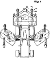
- a large-area lawn mower with sickle mowers is shown schematically.
- Such lawn mowers have a relatively large working width, and the outer side mowers can be folded up into a transport position.
- the preferred exemplary embodiment is less concerned with the large-area lawn mower and more with a pendulum or trailing wheel arrangement 10 for the individual mower units, whether they are attached to the side or in front of the vehicle.
- the tire running on the ground is designated by 12, a hub-rim part receiving the tire by 14 and the wheel axle by 16.
- a fork 18 engages, which in the usual way with the vertical bolt or vertical Swivel pin 20 is provided.
- the vertical bolt 20 is rotatable in an opening 22 which is provided in a fastening part 24.
- the fastening part 24 in turn is connected via screws 26 to brackets 28, which create a four-bar linkage between the fastening part 24 and a mower housing 30.
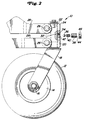
- a mechanism which prevents the pendulum wheel 12 from rotating when it is lifted off the ground.
- This mechanism essentially holds the pendulum wheel in its forward-facing position.
- the vertical shaft 20 is round in cross section over almost its entire length.
- the round cross section is designated by 32, with, as can be seen from FIGS. 2 to 5, a flattening 34 being provided in a certain area.
- a stop part or a ball 36 is arranged in a threaded part 38 and is pressed against the vertical shaft 20 via a pressure part, such as a pressure spring 40.
- the threaded part 38 can be screwed into a threaded bore 42 provided in the fastening part 24.
- the threaded part 38 is equipped with a central bore 44 which receives the spring 40 and partially the ball 36. At the end remote from the ball, the central bore can be closed by a nut 46 and thus prevents the ball and spring from falling out in the assembled state.
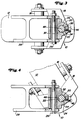
- the pendulum wheel 12 rolls on the floor surface or has contact with it. If the lawnmower makes a curve, the pendulum wheel pivots about its vertical axis so that the tire 12 remains in contact with the ground without erasing or injuring the turf.
- the vertical shaft 20 rotates in the opening 22 in the fastening part 24.
- the vertical shaft 20 rotates from its position shown in FIGS. 2 and 3, in which the flat 34 is oriented towards the front is.
- the flat 34 is initially rotated, the ball 36 is pushed into the central bore 44 of the threaded part in the direction of the nut 46, the spring 40 being compressed.
- the pendulum wheel can pivot through a large range of motion when cornering, with the tire 12 maintaining its contact with the ground.
- the pendulum wheel is also prevented from rotating, since the spring mechanism wants to hold the vertical shaft in the forwardly oriented position according to FIG. 3.
- a gyroscope can occur when the pendulum wheel is lifted off the ground, for example when swiveling up or lifting a mower. In such a case, forces can occur that rotate or spin the pendulum wheel. If the vertical shaft begins to rotate with the mower raised, then it will eventually assume the position shown in FIG. 5, for example if it has been rotated somewhat from the position shown in FIG. 3. In the position according to FIG. 5, the flattened portion 34 presses the ball 36 outwards, the compression spring 40 being slightly pressed together.
- the spring will exert a counterforce on the ball in the direction of the surface of the vertical shaft, specifically in the direction of arrow A, that is to say perpendicular to the flattened portion 34 the central axis 48 of the vertical shaft 20 is directed, a power arm 50 is created so that the vertical shaft is rotated back into its position according to FIG. 3. In the position according to FIG. 3, the force A is then directed onto the central axis 48 and the vertical shaft is held in this position.
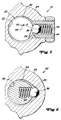
- FIG. 6 A further exemplary embodiment 52 is shown in FIG. 6.
- the spring 40 and part of the ball 36 are arranged in a bore in the vertical shaft as shown in FIG. 6.
- the ball 36 is thus pressed outwards by the spring 40 against the inner circumference 54 of the bore in the fastening part 24 receiving the vertical shaft of the pendulum wheel.
- this bore is essentially round, the round section being designated by 58.
- the round section is interrupted by a recessed section 60 which has ramp-like sides so that the ball can also emerge again. If the mower now makes a turn, then the pendulum wheel swivels again, the vertical shaft of which rotates. The ball is pressed against the action of the spring 40 from the recessed section 60.
- the spring remains compressed as long as the ball 36 bears against the round section 58.
- the force then acting against the inner circumference is so great that gyro is prevented. Should a gyroscope nevertheless occur, the ball comes back into the recessed area 60, where the spring is relaxed and compressed again.
- the compression absorbs energy, which contributes to the pendulum wheel coming to a standstill.
- the pendulum wheel is returned to its forward-facing position and also held there. If the vertical shaft rotates somewhat from its position according to FIG. 6, the ball is pressed against the spring when the side edges of the recessed section 60 press the ball inwards. The spring naturally creates a counter pressure that pushes the ball outwards. As a result of the side edges of the recessed section, a direction of force arises which does not run through the central axis of the vertical shaft and thus a force arm which rotates the vertical shaft back into its position according to FIG. 6. 6, the direction of force again runs through the central axis, so that the pendulum wheel can be held in this position.
Landscapes
- Engineering & Computer Science (AREA)
- Mechanical Engineering (AREA)
- Harvester Elements (AREA)
- Motorcycle And Bicycle Frame (AREA)
Abstract
Ein Nachlaufrad mit einem vertikalen Schwenkzapfen (20), der in einer in einem Befestigungsteil (24) vorgesehenen Öffnung (22) drehbar angeordnet ist, hat, um die Gefahr des unkontrollierten Kreiselns zu vermeiden, einen unter Federwirkung stehenden Anschlagteil (36), der gegen den Schwenkzapfen (20) bzw. gegen den inneren Umfang der Öffnung (22) zur Anlage bringbar ist.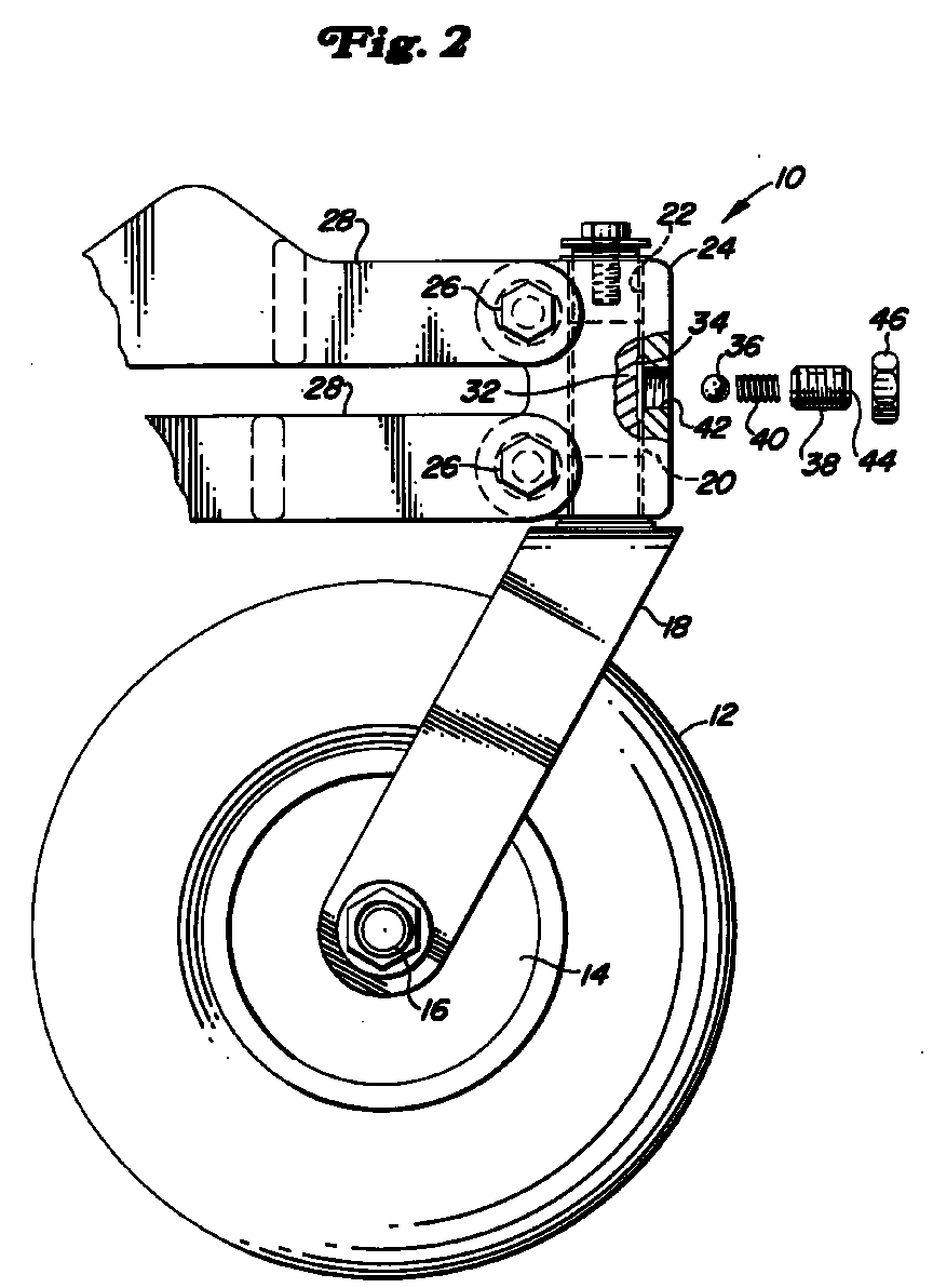
Description
Die Erfindung bezieht sich auf ein Nachlaufrad mit einem vertikalen Schwenkzapfen, der in einer in einem Befestigungsteil vorgesehenen Öffnung drehbar angeordnet ist.The invention relates to a trailing wheel with a vertical pivot pin which is rotatably arranged in an opening provided in a fastening part.
Dieses bekannte Nachlaufrad (US-A-4 854 112) ist eines der Stützräder für eine Schneideinheit eines Rasenmähers. Bekanntlich schwenken derartige Räder mit, wenn der Mäher seine Fahrtrichtung beispielsweise bei Kurvenfahten ändert. Da die Nachlaufräder dann mitschwenken, sind Rasenbeschädigungen eher selten. Andererseits haben derartige Nachlaufräder die Eigenart, dass sie zu einem Kreiseln neigen, wenn sie vom Boden abgehoben sind. Bei der Verwendung dieser Nachlaufräder an Schneideinheiten kommt es natürlich häufig vor, dass die Räder keinen Bodenkontakt haben, beispielsweise dann, wenn die Schneideinheit hochgeschwenkt wurde. Dann kreiselnde Nachlaufräder verursachen lästige Geräusche. Um die Gefahr des Kreiselns zu reduzieren sind bereits sogenannte Spannkappen vorgeschlagen worden. Diese verhindern aber nicht, dass, wenn das Nachlaufrad wieder Bodenberührung hat, das Nachlaufrad eine Stellung einnimmt, die der gewünschten Fahrtrichtung nicht entspricht. Das Rad dreht sich auf dem Boden in die richtige Richtung bei einem Anfahren, wobei dann Oberflächenbeschädigungen auftreten, was im Fall von Golfplätzen im höchsten Maß unerwünscht ist.This known trailing wheel (US-A-4 854 112) is one of the support wheels for a cutting unit of a lawnmower. As is known, such wheels also pivot when the mower changes its direction of travel, for example when cornering. Since the trailing wheels then swivel, damage to the lawn is rather rare. On the other hand, such trailing wheels have the characteristic that they tend to spin when they are lifted off the ground. Of course, when using these trailing wheels on cutting units, it often happens that the wheels have no contact with the ground, for example when the cutting unit has been swung up. Then rotating trailing wheels cause annoying noises. So-called clamping caps have already been proposed to reduce the risk of spinning. However, these do not prevent the trailing wheel from assuming a position that does not correspond to the desired direction of travel when the trailing wheel comes into contact with the ground again. The wheel turns on the ground in the right direction when starting off, which then causes surface damage, which is extremely undesirable in the case of golf courses.
Die mit der Erfindung zu lösende Aufgabe wird nach einem ersten Aspekt darin gesehen, bei pendelnden Nachlaufrädern die Gefahr des Kreiseln zumindest zu reduzieren, weshalb nach der Erfindung zunächst ein unter Federwirkung stehender Anschlagteil vorgesehen ist, der gegen den Schwenkzapfen bzw. gegen den inneren Umfang der Öffnung zur Anlage bringbar ist. Auf diese Weise wirkt der Anschlagteil wie eine Laufbremse, die ein kreiselndes Nachlaufrad, sofort zum Stillstand bringt, wenn es überhaupt zu einem Kreiseln kommen sollte.According to a first aspect, the object to be achieved with the invention is seen in at least reducing the risk of gyration in the case of oscillating trailing wheels, which is why, according to the invention, a spring-loaded stop part is initially provided, which against the pivot pin or against the inner circumference of the Opening can be brought to the system. In this way, the stop part acts like a running brake, which brings a rotating trailing wheel to a standstill immediately, if there should ever be a rotation.
Nach einem werteren Aspekt der Erfindung soll nicht nur das Kreiseln verhindert werden, sondern auch die Möglichkeit geschaffen werden, dass das Nachlaufrad in einer vorgegebenen Stellung, die in der Regel der Geradeausfahrt entspricht, wieder Bodenberührung bekommt. Hierzu ist vorgesehen, dass der Anschlagteil gegen eine Rastfläche zur Anlage bringbar ist, wobei Anschlagteil und Rastfläche zueinander relativ drehbar und an dem Befestigungsteil und Schwenkzapfen vorgesehen sind. Die Rastfläche bestimmt dabei die vorgegebene Stellung, in der das Nachlaufrad gehalten wird. Die Rastfläche ist dabei so ausgebildet, dass der Anschlagteil bei Kontakt mit der Rastfläche das Nachlaufrad in die vorherbestimmte Stellung zwingt.According to a further aspect of the invention, not only should the gyroscope be prevented, but also the possibility should be created for the trailing wheel to come into contact with the ground again in a predetermined position, which generally corresponds to driving straight ahead. For this purpose, it is provided that the stop part can be brought into abutment against a latching surface, the stop part and latching surface being rotatable relative to one another and provided on the fastening part and pivot pin. The locking surface determines the predetermined position in which the trailing wheel is held. The locking surface is designed such that the stop part forces the trailing wheel into the predetermined position when it comes into contact with the locking surface.
Die Rastfläche kann in einfacher Weise dadurch gebildet werden, dass die Mantelfäche des Schwenkzapfens mit einer Abflachung versehen ist, gegen die der Anschlagteil zur Anlage bringbar ist, wobei der Anschlagteil aus einer federbelasteten Kugel bestehen kann, die im montierten Zustand zusammen mit der Feder in einer in den Befestigungsteil eingearbeiteten Bohrung vorgesehen ist und gegen den Schwenkzapfen drückt.The latching surface can be formed in a simple manner in that the jacket surface of the pivot pin is provided with a flattened surface against which the stop part can be brought into abutment, wherein the stop part can consist of a spring-loaded ball, which in the assembled state together with the spring in one is provided in the mounting part machined hole and presses against the pivot pin.
Andererseits ist es aber im Rahmen der Erfindung auch möglich, dass die den Schwenkzapfen aufnehmende Öffnung mit einem ausgesparten Abschnitt, der dann die Rastfläche bildet, versehen ist, gegen den der Anschlagteil anliegt. Dabei ist der ausgesparte Abschnitt praktisch als Vertiefung mit rampenförmigen Kanten ausgebildet, die den Schwenkzapfen in die vorgegebene Position zwingen, wobei der Schwenkzapfen mit einer Radialbohrung versehen ist, die den aus einer federbelasteten Kugel bestehenden Anschlagteil zusammen mit der Feder aufnimmt.On the other hand, it is also possible within the scope of the invention that the opening receiving the pivot pin is provided with a recessed section, which then forms the latching surface, against which the stop part bears. The recessed section is practically formed as a recess with ramp-shaped edges which force the pivot pin into the predetermined position, the pivot pin being provided with a radial bore which receives the stop part consisting of a spring-loaded ball together with the spring.
Im Rahmen der Erfindung kann das Nachlaufrad an einem Mähwerk eines Rasenmähers vorgesehen sein, weil sich die Vorteile des erfindungsgemäßen Nachlaufrades bei Rasenmähern besonders positiv auswirken.In the context of the invention, the trailing wheel can be provided on a mower of a lawnmower, because the advantages of the trailing wheel according to the invention have a particularly positive effect on lawnmowers.
In der Zeichnung ist ein nachfolgend näher erläutertes Ausführungsbeispiel der Erfindung in zwei Varianten dargestellt. Es zeigt:
- Fig. 1
- einen Großflächenrasenmäher mit mit Nachlaufrädern ausgerüsteten Schneideinheiten in schematischer Darstellung,
- Fig. 2
- ein gegen Kreiseln festellbares Nachlaufrad in größerern Maßstab,
- Fig. 3
- den in einen Befestigungsteil eingesetzten Vertikalbolzen des Nachlaufrades im Schnitt und in vorgegebener Geradeausstellung,
- Fig. 4
- eine ähnliche Darstellung wie in Fig. 3, wobei jedoch das Nachlaufrad aus seiner Geradeausstellung verschwenkt ist,
- Fig. 5
- einen gegen den Schwenkbolzen anliegenden federbelasteten Anschlagteil in Form einer Kugel und
- Fig. 6
- einen gegen den inneren Umfang der den Schwenkbolzen aufnehmenden Bohrung anliegenden federbelasteten Anschlagteil.
- Fig. 1
- a large area lawn mower with cutting units equipped with trailing wheels in a schematic representation,
- Fig. 2
- a trailing wheel that can be locked against gyroscopes on a larger scale,
- Fig. 3
- the vertical bolt of the trailing wheel inserted into a fastening part in section and in the specified straight-ahead position,
- Fig. 4
- 3 shows a similar representation as in FIG. 3, but with the trailing wheel pivoted out of its straight-ahead position,
- Fig. 5
- a spring-loaded stop part abutting against the pivot pin in the form of a ball and
- Fig. 6
- a spring-loaded stop part abutting against the inner circumference of the bore receiving the pivot pin.
In Fig. 1 der Zeichnung ist ein Großflächenrasenmäher mit Sichelmähwerken schematisch dargestellt. Derartige Rasenmäher haben eine relativ große Arbeitsbreite, und die außenliegenden Seitenmähwerke können in eine Transportstellung hochgeklappt werden. Das bevorzugte Ausführungsbeispiel befasst sich aber weniger mit dem Großflächenrasenmäher sondern mehr mit einer Pendel- oder Nachlaufradanordnung 10 für die einzelnen Mähwerke, seien sie nun seitlich angebracht oder vorne vor dem Fahrzeug. Im einzelnen ist der auf dem Boden ablaufende Reifen mit 12, ein den Reifen aufnehmender Naben-Felgenteil mit 14 und die Radachse mit 16 bezeichnet. An der Radachse 16 greift eine Gabel 18 an, die in üblicher Weise mit dem Vertikalbolzen bzw. vertikalen Schwenkzapfen 20 versehen ist. Der Vertikalbolzen 20 ist in einer Öffnung 22 drehbar, die in einem Befestigungsteil 24 vorgesehen ist. Der Befestigungsteil 24 seinerseits ist über Schrauben 26 mit Auslegern 28 verbunden, die eine aus vier Streben bestehende Gestängeverbindung zwischen dem Befestigungsteil 24 und einem Mähwerksgehäuse 30 schaffen.In Fig. 1 of the drawing, a large-area lawn mower with sickle mowers is shown schematically. Such lawn mowers have a relatively large working width, and the outer side mowers can be folded up into a transport position. However, the preferred exemplary embodiment is less concerned with the large-area lawn mower and more with a pendulum or
Bei dem bevorzugten Ausführungsbeispiel ist ein Mechanismus vorgesehen, der ein Kreiseln des Pendelrades 12 verhindert, wenn dieses vom Boden abgehoben ist. Dieser Mechanismus hält das Pendelrad im wesentlichen in seiner nach vorne orientierten Stellung. Die Vertikalwelle 20 ist fast auf ihrer gesamten Länge im Querschnitt rund. Der runde Querschnitt ist mit 32 bezeichnet, wobei, wie aus den Fig. 2 bis 5 zu erkennen ist, in einem bestimmten Bereich eine Abflachung 34 vorgesehen ist. Ein Anschlagteil oder eine Kugel 36 ist in einem Gewindeteil 38 angeordnet und wird über einen Druckteil, wie eine Druckfeder 40 gegen die Vertikalwelle 20 gedrückt. Der Gewindeteil 38 ist in eine in dem Befestigungsteil 24 vorgesehene Gewindebohrung 42 einschraubbar. Außerdem ist der Gewindeteil 38 mit einer Zentralbohrung 44 ausgestattet, die die Feder 40 und teilweise die Kugel 36 aufnimmt. An dem der Kugel abgelegenen Ende ist die Zentralbohrung über eine Mutter 46 verschließbar und verhindert damit im montierten Zustand ein Herausfallen von Kugel und Feder.In the preferred embodiment, a mechanism is provided which prevents the
Im normalen Arbeitseinsatz rollt das Pendelrad 12 auf der Bodenoberfläche ab bzw. hat mit dieser Kontakt. Durchfährt der Rasenmäher eine Kurve, dann verschwenkt das Pendelrad um seine Vertikalachse, so dass der Reifen 12 weiter Bodenkontakt hat, ohne zu radieren oder die Grasnarbe zu verletzen. Wenn das Pendelrad verschwenkt, dreht sich die Vertikalwelle 20 in der Öffnung 22 im Befestigungsteil 24. Wenn der Rasenmäher seine Geradeausfahrt ändert, dreht sich die Vertikalwelle 20 aus ihrer in den Fig. 2 und 3 gezeigten Stellung, in der die Abflachung 34 nach vorne orientiert ist. Bei einem anfänglichen Drehen der Abflachung 34 wird die Kugel 36 in die Zentralbohrung 44 des Gewindeteils in Richtung auf die Mutter 46 gedrängt, wobei die Feder 40 zusammengedrückt wird. Bei einem weiteren Drehen der Vertikalwelle wird die Kugel schließlich gegen den kreisrunden Teil 32 der Vertikalwelle zur Anlage kommen, wie es in Fig. 4 angedeutet ist. Bei dem bevorzugten Ausführungsbeispiel kann damit das Pendelrad bei Kurvenfahrten durch einen großen Bewegungsbereich schwenken, wobei der Reifen 12 seinen Bodenkontakt beibehält.In normal work, the
Bei dem vorliegenden Ausführungsbeispiel ist das Pendelrad auch daran gehindert zu kreiseln, da der Federmechanismus die Vertikalwelle in der nach vorne ausgerichteten Stellung nach Fig. 3 halten will. Ein Kreiseln kann auftreten, wenn das Pendelrad vom Boden abgehoben ist, beispielsweise bei einem Hochschwenken oder Anheben eines Mähwerkes. In einem solchen Fall können Kräfte auftreten, die das Pendelrad umlaufen oder kreiseln lassen. Beginnt die Vertikalwelle bei ausgehobenem Mähwerk zu drehen, dann wird sie irgendwann die Stellung nach Fig. 5 einnehmen, beispielsweise wenn sie etwas aus der Stellung nach Fig. 3 gedreht wurde. In der Stellung nach Fig. 5 drückt die Abflachung 34 die Kugel 36 nach außen, wobei die Druckfeder 40 leicht zusammen gepresst wird. Die Feder wird dabei aber auf die Kugel eine Gegenkraft in Richtung auf die Oberfläche der Vertikalwelle ausüben, und zwar in Richtung des Pfeiles A, also senkrecht zur Abflachung 34. Da die Kraft A damit nicht auf die Zentralachse 48 der Vertikalwelle 20 gerichtet ist, entsteht ein Kraftarm 50, so dass die Vertikalwelle in ihre Stellung nach Fig. 3 zurück gedreht wird. In der Stellung nach Fig. 3 ist dann die Kraft A auf die Zentralachse 48 gerichtet und die Vertikalwelle wird in dieser Stellung gehalten.In the present exemplary embodiment, the pendulum wheel is also prevented from rotating, since the spring mechanism wants to hold the vertical shaft in the forwardly oriented position according to FIG. 3. A gyroscope can occur when the pendulum wheel is lifted off the ground, for example when swiveling up or lifting a mower. In such a case, forces can occur that rotate or spin the pendulum wheel. If the vertical shaft begins to rotate with the mower raised, then it will eventually assume the position shown in FIG. 5, for example if it has been rotated somewhat from the position shown in FIG. 3. In the position according to FIG. 5, the flattened
In Fig. 6 ist ein weiteres Ausführungsbeispiel 52 dargestellt. Bei diesem Ausführungsbeispiel sind die Feder 40 und ein Teil der Kugel 36 nach der Darstellung in Fig. 6 in einer Bohrung in der Vertikalwelle angeordnet. Damit wird die Kugel 36 durch die Feder 40 nach außen gegen den inneren Umfang 54 der die Vertikalwelle des Pendelrades aufnehmenden Bohrung im Befestigungsteil 24 gedrückt. Wie aus Fig. 6 erkennbar ist, ist diese Bohrung im wesentlichen rund, wobei der runde Abschnitt mit 58 bezeichnet ist. Der runde Abschnitt wird durch einen ausgesparten Abschnitt 60 unterbrochen, der rampenähnliche Seiten aufweist, damit die Kugel auch wieder austreten kann. Durchfährt nun der Mäher eine Kurve, dann verschwenkt wiederum das Pendelrad, wobei dessen Vertikalwelle sich dreht. Dabei wird die Kugel gegen die Wirkung der Feder 40 aus dem vertieften Abschnitt 60 gedrückt. Die Feder bleibt zusammengedrückt, solange die Kugel 36 gegen den runden Abschnitt 58 anliegt. Die dann gegen den inneren Umfang wirkende Kraft ist so groß, dass ein Kreiseln verhindert wird. Sollte dennoch ein Kreiseln auftreten, so kommt die Kugel wieder in den ausgesparten Bereich 60, wo die Feder entspannt und wieder zusammengedrückt wird. Das Zusammendrücken absorbiert Energie, was dazu beiträgt, dass das Pendelrad zum Stillstand kommt.A further
Auch bei der Ausführung nach Fig. 5 wird das Pendelrad nach einem leichten Einschlag wieder in seine nach vorne gerichtete Stellung zurückgeführt und auch dort gehalten. Verdreht sich die Vertikalwelle etwas aus ihrer Stellung nach Fig. 6, dann wird die Kugel gegen die Feder gedrückt, wenn die Seitenkanten des ausgesparten Abschnittes 60 die Kugel nach innen drücken. Die Feder erzeugt dabei natürlich einen Gegendruck, der die Kugel nach außen drückt. Infolge der Seitenkanten des ausgesparten Abschnittes entsteht eine Kraftrichtung, die nicht durch die Zentralachse der Vertikalwelle verläuft und damit ein Kraftarm, der die Vertikalwelle in ihre Position nach Fig. 6 zurückdreht. In der Stellung nach Fig. 6 verläuft die Kraftrichtung wieder durch die Zentralachse, so dass das Pendelrad in dieser Stellung gehalten werden kann.5, after a slight impact, the pendulum wheel is returned to its forward-facing position and also held there. If the vertical shaft rotates somewhat from its position according to FIG. 6, the ball is pressed against the spring when the side edges of the recessed
Claims (7)
Applications Claiming Priority (2)
| Application Number | Priority Date | Filing Date | Title |
|---|---|---|---|
| US645365 | 1991-01-24 | ||
| US08/645,365 US5727285A (en) | 1996-05-13 | 1996-05-13 | Caster wheel biasing mechanism |
Publications (2)
| Publication Number | Publication Date |
|---|---|
| EP0807540A2 true EP0807540A2 (en) | 1997-11-19 |
| EP0807540A3 EP0807540A3 (en) | 1999-04-28 |
Family
ID=24588713
Family Applications (1)
| Application Number | Title | Priority Date | Filing Date |
|---|---|---|---|
| EP97107539A Withdrawn EP0807540A3 (en) | 1996-05-13 | 1997-05-07 | Castor |
Country Status (3)
| Country | Link |
|---|---|
| US (1) | US5727285A (en) |
| EP (1) | EP0807540A3 (en) |
| CA (1) | CA2194596A1 (en) |
Families Citing this family (21)
| Publication number | Priority date | Publication date | Assignee | Title |
|---|---|---|---|---|
| US5943735A (en) * | 1995-01-16 | 1999-08-31 | Flexello Limited | Shopping trolley, a castor for a shopping trolley and a kit of parts for fitting to such a castor |
| US6115882A (en) * | 1997-01-22 | 2000-09-12 | United Auto Systems Inc. | Caster with a shaped stem |
| US6212733B1 (en) * | 1999-08-16 | 2001-04-10 | Link Treasure Limited | Hub and wheel assembly with automatic moving direction adjustment mechanism |
| US6402166B1 (en) * | 2000-09-19 | 2002-06-11 | Ping-Jan Chiu | Locking device for limiting swiveling movement of a front wheel of a stroller |
| US6745873B1 (en) * | 2003-01-29 | 2004-06-08 | Hsi-Yuan Shawn Chen | Braking device for an exercising cycle |
| US20040168283A1 (en) * | 2003-02-28 | 2004-09-02 | Branham Tillman Wade | Controlled caster wheel |
| ES2253982B1 (en) * | 2004-05-14 | 2007-08-01 | Jose Mani Molins | AUXILIARY DEVICE FOR THE DISPLACEMENT OF STRETCHERS AND SIMILAR. |
| NL1029369C2 (en) * | 2005-06-29 | 2007-01-02 | Wellco Mobility Oldenzaal B V | Swivel-wheel assembly and vehicle provided with such an assembly. |
| EP1792750A1 (en) * | 2005-12-05 | 2007-06-06 | Invacare International Sàrl | Removable wheel support device for a wheelchair |
| US20080148514A1 (en) * | 2006-12-20 | 2008-06-26 | Hancock Garry W | Direction stabilized compact swivel caster |
| US20080209673A1 (en) * | 2007-02-23 | 2008-09-04 | Cooper Rory A | Caster and system for mobile device |
| US8490242B2 (en) * | 2007-02-23 | 2013-07-23 | Universit Of Pittsburgh—Of the Commonwealth System of Higher Education | Mobile caster |
| US20090205164A1 (en) * | 2008-02-19 | 2009-08-20 | Larson Albert W | Castor Wheel Assembly |
| US7574850B1 (en) * | 2008-06-10 | 2009-08-18 | Deere & Company | Caster wheel locking system for walk-behind mower |
| US20090309331A1 (en) * | 2008-06-13 | 2009-12-17 | Harold James Ryan | Trailer apparatus including adjustable wheel assemblies |
| US8276240B2 (en) * | 2008-09-03 | 2012-10-02 | Roman Ritachka | Door mounted finger safety device |
| US8235419B1 (en) | 2009-04-10 | 2012-08-07 | Peter Anthony Giarrusso | Lateral stability system for a vehicle |
| US20110314635A1 (en) * | 2010-06-28 | 2011-12-29 | Yuan Deng Metals Industrial Co., Ltd. | Hinge |
| US8875855B2 (en) | 2012-02-24 | 2014-11-04 | Travelpro International Inc. | Wheeled luggage case |
| BE1021113B1 (en) * | 2012-10-01 | 2015-12-18 | Cnh Industrial Belgium Nv | SWIVEL WHEEL WHOLE OF A GRAPHER FOR A AGRICULTURAL MACHINE |
| JP7404538B2 (en) * | 2019-12-16 | 2023-12-25 | ワンダーランド スイツァーランド アーゲー | Vibration damping device adapted for the wheels of child carriers |
Family Cites Families (12)
| Publication number | Priority date | Publication date | Assignee | Title |
|---|---|---|---|---|
| US2583858A (en) * | 1949-12-10 | 1952-01-29 | Jarvis & Jarvis Inc | Automatic swivel locking caster |
| US2960717A (en) * | 1957-09-03 | 1960-11-22 | Aerol Co Inc | Caster swivel control device |
| US3390486A (en) * | 1966-01-24 | 1968-07-02 | Herbert J. Walters | Pivoting shower door |
| US3699609A (en) * | 1971-04-12 | 1972-10-24 | William L Spatz | Spring loaded caster for shop tools, bar stools and the like |
| US3851354A (en) * | 1972-10-11 | 1974-12-03 | Amerock Corp | Self-closing butt hinge |
| DE2422154A1 (en) * | 1974-05-08 | 1975-11-27 | Schulte Soehne Kg A | STEERING CASTOR FOR EQUIPMENT, FURNITURE, ETC. ESPECIALLY SICK BEDS |
| DE3303822A1 (en) * | 1983-02-04 | 1984-08-09 | Film-Geräte-Verleih Schmidle & Fitz, 8000 München | SUPPORT WHEEL ARRANGEMENT FOR A CAMERA VEHICLE |
| JPS6025803A (en) * | 1983-07-22 | 1985-02-08 | Kassai Inc | Caster |
| CA1284258C (en) * | 1987-07-17 | 1991-05-21 | Darnell Inc. | Keyed mounting assembly for lockable swivel caster |
| US4942726A (en) * | 1987-08-28 | 1990-07-24 | Deere & Company | Mechanism and method for converting a fixed wheel walk-behind mower to a caster wheel walk-behind mower and vice versa |
| US4854112A (en) * | 1987-09-04 | 1989-08-08 | The Toro Company | Turf maintenance apparatus |
| CA2062630C (en) * | 1992-01-13 | 1995-06-13 | Allen Riblett | Detent hinge |
-
1996
- 1996-05-13 US US08/645,365 patent/US5727285A/en not_active Expired - Fee Related
-
1997
- 1997-01-07 CA CA002194596A patent/CA2194596A1/en not_active Abandoned
- 1997-05-07 EP EP97107539A patent/EP0807540A3/en not_active Withdrawn
Also Published As
| Publication number | Publication date |
|---|---|
| EP0807540A3 (en) | 1999-04-28 |
| CA2194596A1 (en) | 1997-11-14 |
| US5727285A (en) | 1998-03-17 |
Similar Documents
| Publication | Publication Date | Title |
|---|---|---|
| EP0807540A2 (en) | Castor | |
| DE3732664C1 (en) | Aircraft towing vehicle - handlebar-controlled lifting bucket | |
| EP0518168B1 (en) | Steering device for a vehicle, especially a light garden tractor or lawn mower | |
| DE68906956T2 (en) | Device for adjusting the length of motor vehicle suspension arms. | |
| DE2702743C2 (en) | Haymaking machine for tedding / turning and swathing with one or more rotation-driven rake wheels | |
| EP0467181A1 (en) | Hydrostatic transmission for a vehicle with wheel brakes | |
| DE102017214963A1 (en) | Central joint for a three-point link | |
| EP3360405A1 (en) | Cutting head for a motor strimmer | |
| EP1863694A2 (en) | Swivel wheel unit and wheelchair comprising at least one swivel wheel unit | |
| DE3021605A1 (en) | Haymaking machine for swathing, turning and tedding | |
| DE69307127T2 (en) | TOWING MACHINE | |
| DE69403511T2 (en) | Haymaking machine | |
| DE2146655A1 (en) | Haymaking machine | |
| DE1507341B2 (en) | TRACTOR-TOWED HAYMAKING MACHINE | |
| DE102010012666B4 (en) | Ride-on mower with height adjustment | |
| EP1817953B1 (en) | Device for lawn, garden or terrain maintenance and working height adjusting device | |
| DE2719797C2 (en) | Haymaking machine for optional turning / tedding or swathing with at least two rotating driven rake wheels | |
| DE2904244C2 (en) | ||
| EP0033936B2 (en) | Lock with swingable member for a vehicle, in particular a bicycle | |
| DE19741742C2 (en) | Pallet truck with support wheel | |
| DE20317770U1 (en) | Device for adjusting the seat position of a saddle in a vehicle | |
| DE9414597U1 (en) | Drawn mower | |
| DE2850215A1 (en) | Cylinder type lawn-mower cutting system - has height adjustment which acts on roller and land wheels simultaneously | |
| DE2554273A1 (en) | Swinging supporting wheel for rotary plough - has wheel support extending obliquely downwards in working position | |
| DE3707856C2 (en) | Mounted reversible plow |
Legal Events
| Date | Code | Title | Description |
|---|---|---|---|
| PUAI | Public reference made under article 153(3) epc to a published international application that has entered the european phase |
Free format text: ORIGINAL CODE: 0009012 |
|
| AK | Designated contracting states |
Kind code of ref document: A2 Designated state(s): DE FR GB IE IT |
|
| PUAL | Search report despatched |
Free format text: ORIGINAL CODE: 0009013 |
|
| AK | Designated contracting states |
Kind code of ref document: A3 Designated state(s): DE FR GB IE IT |
|
| STAA | Information on the status of an ep patent application or granted ep patent |
Free format text: STATUS: THE APPLICATION IS DEEMED TO BE WITHDRAWN |
|
| 18D | Application deemed to be withdrawn |
Effective date: 19991201 |