EP0807034B1 - Commodo a fonctions multiples - Google Patents
Commodo a fonctions multiples Download PDFInfo
- Publication number
- EP0807034B1 EP0807034B1 EP96904501A EP96904501A EP0807034B1 EP 0807034 B1 EP0807034 B1 EP 0807034B1 EP 96904501 A EP96904501 A EP 96904501A EP 96904501 A EP96904501 A EP 96904501A EP 0807034 B1 EP0807034 B1 EP 0807034B1
- Authority
- EP
- European Patent Office
- Prior art keywords
- control knob
- rotational position
- shaft
- ring
- control
- Prior art date
- Legal status (The legal status is an assumption and is not a legal conclusion. Google has not performed a legal analysis and makes no representation as to the accuracy of the status listed.)
- Expired - Lifetime
Links
Images


Classifications
-
- B—PERFORMING OPERATIONS; TRANSPORTING
- B60—VEHICLES IN GENERAL
- B60Q—ARRANGEMENT OF SIGNALLING OR LIGHTING DEVICES, THE MOUNTING OR SUPPORTING THEREOF OR CIRCUITS THEREFOR, FOR VEHICLES IN GENERAL
- B60Q1/00—Arrangement of optical signalling or lighting devices, the mounting or supporting thereof or circuits therefor
- B60Q1/02—Arrangement of optical signalling or lighting devices, the mounting or supporting thereof or circuits therefor the devices being primarily intended to illuminate the way ahead or to illuminate other areas of way or environments
- B60Q1/04—Arrangement of optical signalling or lighting devices, the mounting or supporting thereof or circuits therefor the devices being primarily intended to illuminate the way ahead or to illuminate other areas of way or environments the devices being headlights
- B60Q1/14—Arrangement of optical signalling or lighting devices, the mounting or supporting thereof or circuits therefor the devices being primarily intended to illuminate the way ahead or to illuminate other areas of way or environments the devices being headlights having dimming means
- B60Q1/1446—Arrangement of optical signalling or lighting devices, the mounting or supporting thereof or circuits therefor the devices being primarily intended to illuminate the way ahead or to illuminate other areas of way or environments the devices being headlights having dimming means controlled by mechanically actuated switches
- B60Q1/1453—Hand actuated switches
- B60Q1/1461—Multifunction switches for dimming headlights and controlling additional devices, e.g. for controlling direction indicating lights
- B60Q1/1469—Multifunction switches for dimming headlights and controlling additional devices, e.g. for controlling direction indicating lights controlled by or attached to a single lever, e.g. steering column stalk switches
- B60Q1/1476—Multifunction switches for dimming headlights and controlling additional devices, e.g. for controlling direction indicating lights controlled by or attached to a single lever, e.g. steering column stalk switches comprising switch controlling means located near the free end of the lever, e.g. press buttons, rotatable rings
-
- Y—GENERAL TAGGING OF NEW TECHNOLOGICAL DEVELOPMENTS; GENERAL TAGGING OF CROSS-SECTIONAL TECHNOLOGIES SPANNING OVER SEVERAL SECTIONS OF THE IPC; TECHNICAL SUBJECTS COVERED BY FORMER USPC CROSS-REFERENCE ART COLLECTIONS [XRACs] AND DIGESTS
- Y10—TECHNICAL SUBJECTS COVERED BY FORMER USPC
- Y10T—TECHNICAL SUBJECTS COVERED BY FORMER US CLASSIFICATION
- Y10T29/00—Metal working
- Y10T29/49—Method of mechanical manufacture
- Y10T29/49002—Electrical device making
- Y10T29/49105—Switch making
Definitions
- This invention relates to a multifunction switch stalk which can be mounted on a vehicle steering column.
- Modern motor vehicles often include a switch stalk mounted on the vehicle steering column which controls turn signals, headlights or windshield wipers.
- One currently-used switch stalk includes a control knob on the outer end of the switch stalk. The control knob is rotated to selectively actuate vehicle functions such as windshield wipers. The operator can also actuate the windshield wash function by pressing the entire control knob axially inwardly.
- EP-A-0 160 905 discloses a control lever for a vehicle comprising a hollow body with a printed circuit board inside.
- the control lever further comprises a switch with a fixed contact board disposed orthogonally to the printed circuit board, and at least one ring mounted idly on the outside of the body to control the switching of the switch.
- the invention provides a multifunction switch stalk in accordance with the appended claims.
- the present invention provides a sturdy, easily-assembled multifunctional switch stalk which includes controls for both the front and rear wash and wiper functions.
- the front wiper functions are preferably controlled by a rotatable front control knob.
- an axially compressible wash push button on the outer end of the control knob actuates the front windshield wash function.
- the axially compressible wash push button permits the front control knob to remain axially fixed.
- the front control knob does not cover the function graphics on the switch stalk and does not expose grease from within the switch stalk. Moreover, this arrangement facilitates the assembly of the switch.
- the wash push button includes an extended wash push leg slidable through a passage in the control knob and abutting a wash leg of a metal contactor. Upon axial compression of the wash push button the extended wash push leg bends the wash leg of the metal contactor causing the wash leg to make conductive contact with a electrical contact on a printed circuit board. This actuates the wash function.
- a control ring is incorporated into the switch.
- the rear wiper and wash functions are controlled by a rear control ring.
- the rear control ring actuates a rear window wash in extreme rotational positions.
- a spring return biases the rear control ring back from the rear wash position upon release of the control ring by the operator.
- a function ring is non-rotatably mounted between the control ring and the control knob.
- the function ring includes two sets of detents, each including two ramps. Each set of detents engages a detent finger biased from the control ring. At each rotational extreme, the detent fingers ride up ramps thereby compressing the detent spring. The compressed detent springs bias the detent fingers back down the ramps thereby returning the control ring from the extreme position upon release of the control ring by the operator.
- the addition of the rear wiper/wash control ring to the switch stalk eliminates a set of controls from the instrument panel and locates the rear wipe/wash controls conveniently near the front wipe/wash controls.
- the control ring actuates the rear wash function in two extreme rotational positions. Therefore the wash function can be conveniently actuated from either a wipe position or the off position, with the spring return returning the control ring upon release of the control ring by the operator.
- the multifunction switch stalk components are mounted sequentially on the shaft outwardly to the front control knob and retained by a snap ring on the end of the shaft. Since all of the components can be simply slid onto the shaft, assembly is quite simple. In addition, once all the components are mounted on the shaft, play between adjacent parts is reduced and there is no build up of tolerances. A wash push button is then snap fit onto the outer end of the control knob, concealing the shaft and the snap ring.
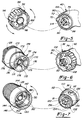
- a multifunction switch stalk 20 according to the present invention is shown in Figure 1 mounted on a vehicle steering column 22.
- the present invention includes controls for the front windshield wipers, a front windshield wash, the rear wipers, and a rear wash. Accordingly various components are designated “front” or “rear.” However it should be apparent that the multifunction switch stalk 20 could be used to control other vehicle functions.
- the multifunction switch stalk 20 has an inner end 24 and an outer end 26.
- a generally cylindrical control knob 28 has an inner end 30 and a tapered outer end 32 and is rotatable on the outer end 26 of the multifunction switch stalk 20 to selectively actuate vehicle functions, such as the front windshield wipers.
- the outer end 32 of the control knob 28 includes a wash push button 34 which is axially compressible relative to the control knob 28 to selectively actuate a vehicle function, such as a front windshield wash.
- the multifunction switch stalk 20 further includes a control ring 36 rotatable to selectively actuate predetermined vehicle functions, such as the rear wipers and a rear window wash.
- the control ring 36 actuates a rear window wash in extreme rotational positions and is provided with a spring return from each wash position.
- a generally cylindrical function ring 38 is non-rotatably mounted between the control ring 36 and the control knob 28.
- a plastic handle 40 includes a wedge-shaped base portion 42. The handle 40 further includes an inner cavity 44 accessible by a rear orifice 46 over which a cover 48 is secured. The inner cavity 44 is also accessible by an axial opening (not shown) in the base portion 42 through which wires 52 are routed.
- the wash push button 34 has a closed outer end 54 received within the control knob 28. As shown, a graphic 56 indicates that the wash push button 34 actuates a windshield wash function.
- the base portion 42 of the handle 40 is mounted in an actuator 60 with a pivot pin 62.
- Wires 52 are connected to a wire harness 64.
- rear function graphics 68 indicate various functions of the control ring 36 such as rear wipers and rear window wash.
- the outer end 66 of the handle 40 further includes an extended axial tab 70.
- a key 72 is disposed on the inner circumference of the outer end 66.
- the outer end 66 further includes a first shaft portion 74 which is integral with the handle 40.
- the first shaft portion 74 has a flattened portion 78 and a pair of tapered teeth 80 (one shown) extend from the first shaft portion 74.
- a second shaft portion 81 preferably formed of a metal or a powdered metal, has a diameter less than the diameter of the first shaft portion 74 and is preferably insert-molded with the handle 40 in the first shaft portion 74.
- the second shaft portion 81 has an axial channel 82 extending from the first shaft portion 74 to an outer end 84 of the second shaft portion 81.
- the outer end 84 of the second shaft portion 81 includes a circumferential notch 86 for retaining a snap ring.
- An annular rear printed circuit board 88 includes a plurality of electrical contacts 90 connected to a rear harness assembly 92 which is connected to wires 52.
- the outer circumference of the rear printed circuit board 88 includes a notch 94 to be received on the key 72 to position the rear printed circuit board 88 on the outer end 66 of the handle 40.
- a rear metal contactor 96 includes a plurality of contact legs 98 for connecting selected electrical contacts 90 on the rear printed circuit board 88.
- the control ring 36 includes a pair of axial bores 100 each containing a detent finger 102 biased by a detent spring 104 toward the function ring 38.
- the function ring 38 has a larger diameter portion 110 and a reduced diameter portion 112 separated by an axial abutment ring 114.
- the reduced diameter portion 112 further includes a semi-circular abutment ring 116 adjacent the axial abutment ring 114.
- a cylindrical aperture 118 extends axially through the center of the function ring 38 and includes a key 120 to be received within the axial channel 82 in the second shaft portion 81.
- the reduced diameter portion 112 includes a key 122 at its inner circumference.
- a pair of radial bores 124 (one shown) each contain a detent finger 126 biased radially outwardly by a detent spring 128.
- Front function graphics 130 indicating various functions of the control knob 28 are disposed on the larger diameter portion 110.
- a front printed circuit board 132 includes a plurality of electrical contacts 134 to control wiper speed.
- a semi-circular wash electrical contact 136 is disposed on the outer periphery of the front printed circuit board 132.
- the front printed circuit board 132 further includes a notch 138 to be received on the key 122 at the inner circumference of the reduced diameter portion 112 of the function ring 38.
- a harness assembly 140 disposed on the front printed circuit board 132 connects the wires 52 to the electrical contacts 134 and 136.
- a front metal contactor 142 has a plurality of contact legs 144 including a wash leg 146 for making conductive contact with the electrical contacts 134 and 136 on the front printed circuit board 132.
- the control knob 28 includes an inner cylinder 150 and an axial passage 152 between the inner cylinder 150 and the control knob 28.
- a pair of recesses 154 for engaging snap fit tabs are disposed on the inside of the control knob 28 at the outer end 32.
- a snap ring 156 is receivable within the circumferential notch 86 on the outer end 84 of the second shaft portion 81 for securing the components in the multifunction switch stalk 20.
- a push button return spring 158 is disposed between the control knob 28 and the wash push button 34 to return the wash push button 34 upon release by an operator.
- a wash push leg 160 extends from the wash push button 34 opposite the closed outer end 54 and is slidable in the axial passage 152 in the control knob 28.
- the wash push button 34 further includes a pair of snap fit tabs 162 to be received within the recesses 154 inside the control knob 28.
- the rear printed circuit board 88 is mounted on the first shaft portion 74 of the handle 40 with the notch 94 engaging the key 72 to align the rear printed circuit board 88.
- the control ring 36 includes a slot 166 partially around the inner periphery of the control knob 36 and receivable of the extended axial tab 70 on the outer end 66 of the handle 40.
- the rear metal contactor 96 is mounted on the control ring 36.
- the control ring 36 is rotatably mounted on the first shaft portion 74 with the extended axial tab 70 slidably inserted in the slot 166 to limit the rotational range of movement of the control ring 36.
- the control ring 36 is rotatable on the first shaft portion 74 so that the contact legs 98 of the rear metal contactor 96 make conductive contact with the electrical contacts 90 on the rear printed circuit board 88 thereby actuating a predetermined set of vehicle functions upon rotation of the control ring 36.
- the control ring 36 and electrical contacts 90 actuate a rear window wash in a first rotational position, a rapid rear window wipe in a second rotational position adjacent the first rotational position, a slow rear window wipe in a third rotational position adjacent the second rotational position, off in a fourth rotational position adjacent the third rotational position, and a rear window wash in a fifth rotational position adjacent the fourth rotational position.
- an inner end 170 of the function ring 38 includes a pair of grooves 172 adjacent the cylindrical aperture 118 which receive the teeth 80 on the first shaft portion 74.
- the inner end 170 further includes two sets of detents 174 for engaging the detent fingers 102 in the control ring 36 at three distinct positions.
- Each set of detents 174 for engaging the detent fingers 102 includes high points 175 separating detents 174.
- a pair of ramps 176 are positioned circumferentially outwardly of each outermost detent 174. High points 175 and ramps 176 each extend towards the control ring 36 from the function ring 38.
- the function ring 38 is mounted on the second shaft portion 81 with the key 120 (not shown in this Figure) in the axial cylindrical aperture 118 engaging the axial channel 82 in the second shaft portion 81. Further the tapered teeth 80 on the first shaft portion 74 engage the grooves 172 on the inner end 170 of the function ring 38, preventing rotation of the function ring 38 relative to the handle 40.
- the detent fingers 102 in the rear wiper control ring 82 engage in the detents 174 on the function ring 38 to define three fixed positions, thereby providing tactile feedback to the operator and insuring alignment of the contact legs 98 of the rear metal contactor 96 with the electrical contacts 90 on the rear printed circuit board 88.
- the ramps 176 in the function ring 38 provide a spring return from a first rotational position (rear window wash) to the second rotational position (rapid rear wipers) and from the fifth rotational position (rear window wash) to the fourth rotational position (off).
- the control ring is received at the second, third and fourth positions with the detents finger received in respective detents 174.
- the detent fingers 102 When the control ring 36 is rotated from the second rotational position (rapid rear wipers) to the first position (rear window wash), the detent fingers 102 each ride up a ramp 176 thereby compressing a detent spring 104.
- the compressed detent spring 104 returns the control ring 36 from the first position to the second position upon release of the control ring 36 by the operator.
- the control ring 36 is rotated from a fourth position (off) to a fifth position (rear window wash) the detent fingers 102 ride up another pair of ramps 176 compressing detent springs 104.
- the detent springs 104 bias the detent fingers 102 down the ramps 176 thereby returning the control ring 36 to the fourth position (off) upon the release of the control ring 36 by the operator.
- the operator can therefore conveniently actuate the wash function when the rear wipers are on by rotating the control ring in a first direction to one rotational extreme, or when the rear wipers are off, by rotating the control ring in an opposite second direction to the other rotational extreme.
- the front printed circuit board 132 is mounted on the second shaft portion 81 and in the reduced diameter portion 112 of the function ring 38 with the notch 138 engaging the key 122 on the inner circumference of the reduced diameter portion 112.
- the inner circumference of the inner end 30 of the control knob 28 includes a plurality of detents 180 for engaging the detent fingers 126 in the function ring 38 and an axial stop 182.
- the front metal contactor 142 is mounted within the inner end 30 of the control knob 28 such that the wash leg 146 of the front metal contactor 142 is adjacent the axial passage 152 through the control knob 28.
- the control knob 28 is rotatably mounted on the second shaft portion 81 and the reduced diameter portion 112 of the function ring 38 such that the detent fingers 126 of the function ring 38 engage the detents 180 in the inner end 30 of the control knob 28 and the contact legs 144, not including the wash leg 146, make conductive contact with the wiper speed electrical contacts 134 on the front printed circuit board 132 upon rotation of the control knob 28.
- the axial stop 182 limits the rotational movement of the control knob 28 by abutting the semi-circular abutment ring 116 on the function ring 38.
- the wash leg 146 of the front metal contactor 142 does not make conductive contact with the wash electrical contact 136 on the front printed circuit board 132.
- the wash push leg 158 elastically deforms the wash leg 146 of the front metal contactor 142 causing the wash leg 146 to make conductive contact with the wash electrical contact 136 on the front printed circuit board 132.
- the front windshield wash function is independent of the rotational position of the control knob 28 since the wash electrical contact 136 is curved and is disposed over approximately half of the periphery of the front printed circuit board 132.
- the wash push button 34 is axially compressible independently of the control knob 28, the components may be mounted sequentially on the first shaft portion 74 and second shaft portion 81 from the handle 40 to the outer end 26 as described above and retained with the snap ring 156 or other fastener.
- the outer end 66 of the handle 40 extends slightly within the control ring 36, as does the larger diameter portion 110 of the function ring 38.
- the reduced diameter portion 112 and the axial abutment ring 114 of the function ring 38 are entirely within the control knob 28.
- the function ring 38 is non-rotatable relative to the handle 40.
- control ring 36 By using the control ring 36 to control the rear wipers and wash functions, a set of controls which would otherwise be on the instrument panel can be eliminated. Further, the controls for rear wipers and rear wash are conveniently located near the controls for the front wipers and front wash.
Landscapes
- Engineering & Computer Science (AREA)
- Mechanical Engineering (AREA)
- Switches With Compound Operations (AREA)
Claims (17)
- Une tige de commutation (20) multifonctions comprenant :une poignée ayant une extrémité intérieure (24) et une extrémité extérieure (26), ladite poignée comprenant une partie de base (42) au niveau de ladite extrémité intérieure (24) afin d'être montée sur une colonne de détection d'un véhicule;un arbre (74, 81) ayant un axe et une extrémité extérieure (84) ledit arbre (74, 81) s'étendant depuis ladite extrémité extérieure (26) de ladite poignée;une bague de commande (36) disposée à rotation sur ledit arbre (74, 81) ladite bague de commande (36) étant susceptible de tourner afin d'actionner sélectivement des fonctions de véhicule prédéterminées, ladite bague de commande (36) comprenant au moins trois positions de rotation;
caractérisée en ce que la tige de commutation multifonctions (20) comprend en outre un mécanisme de rappel élastique (104) pour ramener ladite bague de commande (36) depuis une première position de rotation extrême vers une deuxième position de rotation, à la libération de la bague de commande (36) par un opérateur. - Une tige de commutation multifonctions (20) selon la revendication (1) dans laquelle ledit mécanisme de rappel élastique (104) servant à ramener ladite bague de commande (36) depuis une première position de rotation extrême vers une deuxième position de rotation, à la libération de la bague de commande (36) par un opérateur, comprend une rampe (176) et un doigt de détente (102) déplacé par un ressort de détente (104), ledit doigt de détente (102) montant sur ladite rampe (176) lors de la rotation de ladite bague de commande (36) par un opérateur vers une première position de rotation extrême comprimant de ce fait ledit ressort de détente (104), ledit ressort de détente (104) comprimé déplaçant ledit doigt de détente (102) afin de descendre le long de ladite rampe (176) ramenant de ce fait ladite bague de commande (36) depuis ladite première position de rotation extrême vers ladite deuxième position de rotation, à la libération de ladite bague de commande (36) par ledit opérateur.
- La tige de commutation multifonctions (20) selon la revendication 2, dans laquelle ladite plaque de commande (36) est également ramenée depuis une quatrième position de rotation vers une troisième position de rotation avec un doigt de détente (102) montant sur une deuxième rampe (176) comprimant un ressort de détente (104) lors de la rotation de la bague de commande (36) dans une deuxième direction vers ladite quatrième position de rotation, ladite quatrième position de rotation étant une deuxième position de rotation extrême, ledit ressort de détente (104) comprimé déplaçant ledit doigt de détente (102) de façon à descendre le long de ladite deuxième rampe (176), ramenant de ce fait ladite bague de commande (36) depuis ladite quatrième position à ladite troisième position à la libération de ladite bague de commande (36) par ledit opérateur.
- La tige de commutation multifonctions (20) selon la revendication 3, dans laquelle un doigt de détente unique (102) monte à la fois sur lesdites première et deuxième rampes (176).
- La tige de commutation multifonctions (20) selon la revendication 2, dans laquelle lesdites première et deuxième positions de rotation extrêmes actionnent la même fonction de véhicule prédéterminée.
- La tige de commutation multifonctions (20) selon la revendication 1, comprenant en outre un mécanisme de rappel élastique (104) afin de ramener ladite bague de commande (36) depuis une quatrième position de rotation à une troisième position de rotation, à la libération de la bague de commande (36) par un opérateur.
- La tige de commutation multifonctions (20) selon la revendication 6, dans laquelle un mécanisme de rappel élastique (104) unique ramène ladite bague de commande (36) depuis ladite première position de rotation extrême à ladite deuxième position de rotation et depuis ladite quatrième position de rotation à ladite troisième position de rotation.
- Une tige de commutation multifonctions (20) selon la revendication 1, comprenant en outre un bouton de commande (28) disposé sur une extrémité extérieure (84) dudit arbre (74, 81), ledit bouton de commande (28) pouvant tourner par rapport audit arbre (74, 81) afin d'actionner sélectivement un premier jeu de fonctions de véhicule prédéterminé.
- Une tige de commutation multifonctions (20) selon la revendication 8, comprenant en outre une bague de fonction (38) globalement cylindrique montée de façon non-rotative sur ledit arbre (74, 81), entre ledit bouton de commande (28) et ladite bague de commande (36), ledit arbre (74, 81) comprenant une première partie d'arbre (74) et une deuxième partie d'arbre (81), ladite première partie d'arbre (74) dudit arbre (74, 81) s'étendant depuis ladite extrémité extérieure (26) de ladite poignée, ladite deuxième partie d'arbre (81) dudit arbre (74, 81) s'étendant depuis ladite première partie d'arbre (74), ladite première partie d'arbre (74) ayant un diamètre supérieur au diamètre de ladite deuxième partie d'arbre (81), ladite bague de commande (36) étant montée à rotation sur ladite première partie d'arbre (74), ladite bague de fonction (38) étant montée de façon non-rotative sur ledit arbre (74, 81) de façon adjacente à ladite bague de commande (36), ledit bouton de commande (28) étant monté tournant sur ladite deuxième partie d'arbre (81).
- La tige de commutation multifonctions (20) selon la revendication 9, dans laquelle ladite première partie d'arbre (74) dudit arbre (74, 81) est réalisée d'un seul tenant avec ladite poignée, et ladite deuxième partie d'arbre (81) dudit arbre (74, 81) est en métal, ladite deuxième partie d'arbre (81) étant moulée par insertion avec ladite première partie d'arbre (74).
- Une tige de commutation multifonctions (20) selon la revendication 1, dans laquelle ledit arbre (74, 81) comprend une entaille circonférentielle (86) adjacente à ladite extrémité extérieure (84), ledit bouton de commande (28) étant retenu sur ledit arbre (74, 81) par une bague d'encliquetage (156) encliquetée dans ladite entaille circonférentielle (86).
- Une tige de commutation multifonctions (20) selon la revendication 1, comprenant en outre :un bouton de commande (28) disposé sur ladite extrémité extérieure (26) de ladite poignée, ledit bouton de commande (28) pouvant tourner afin d'actionner sélectivement des fonctions de véhicule prédéterminées;un bouton poussoir (34) disposé sur une extrémité extérieure dudit bouton de commande (28), ledit bouton (34) pouvant être comprimé axialement par rapport audit bouton de commande (28) pour actionner sélectivement une fonction de véhicule prédéterminée;un contacteur (142) ayant une pluralité de pattes (144) comportant une première patte (146), ledit contacteur (142) étant monté sur une extrémité axiale intérieure dudit bouton de commande (28) et pouvant tourner avec ledit bouton de commande (28);une pluralité de contacts électriques (134) comprenant un premier contact électrique (136), ladite pluralité de contacts (134) étant disposés adjacents audit contacteur (142), au moins l'une desdites pattes (144) dudit contacteur (142) établissant un contact conducteur avec au moins l'un desdits contacts électriques (134) lors de la rotation dudit bouton de commande (28) pour actionner des fonctions de véhicule prédéterminées; etladite première patte (146) établissant un contact conducteur avec ledit premier contact électrique (136) lors du mouvement axial dudit bouton poussoir (34) actionnant de ce fait une fonction de véhicule prédéterminée.
- Une tige de commutation multifonctions (20) selon la revendication 1, comprenant en outre :un bouton de commande (28) disposé sur ladite poignée, ledit bouton de commande (28) pouvant tourner afin d'actionner sélectivement des fonctions de véhicule prédéterminées;un bouton poussoir (34) disposé sur une extrémité extérieure dudit bouton de commande (28), ledit bouton (34) pouvant être comprimé axialement par rapport audit bouton de commande (28) afin d'actionner sélectivement une fonction de véhicule prédéterminée; etledit arbre (74, 81) comprend une entaille circonférentielle (86) adjacente à ladite extrémité extérieure (84), une bague d'encliquetage (156) encliquetée dans ladite entaille circonférentielle (86) retenant ledit bouton de commande (28) sur ledit arbre (74, 81).
- La tige de commutation multifonctions (20) selon la revendication 13, dans laquelle ledit bouton poussoir (34) s'encliquette dans ledit bouton de commande (28) masquant ladite bague d'encliquetage (156).
- La tige de commutation multifonctions (20) selon la revendication 12, dans laquelle ladite première patte (146) est en métal et ledit bouton de commande (28) comprend en outre un passage (152) s'étendant axialement, ledit bouton poussoir (34) comprenant en outre une patte de poussée (160) disposée à coulissement dans ledit passage (152) dans ledit bouton de commande (28), ladite première patte métallique (146) butant contre ladite patte de poussée (160) dudit bouton poussoir (34) et étant déformée élastiquement lors du mouvement axial dudit bouton poussoir (34), ladite première patte métallique (146) établissant un contact conducteur avec ledit premier contact électrique (136) lors du mouvement axial dudit bouton poussoir (34) actionnant de ce fait une fonction de véhicule prédéterminée.
- La tige de commutation multifonctions (20) selon la revendication 12, dans laquelle ledit premier contact électrique (136) est incurvé de façon que ladite première patte (146) dudit contacteur métallique (142) établisse un contact conducteur avec ledit premier contact électrique (136), indépendamment de la position de rotation dudit bouton de commande (28).
- La tige de commutation multifonctions (20) selon la revendication 12, dans laquelle ledit bouton de commande (28) actionne un essuie-glace de pare-brise et ledit bouton poussoir (34) actionne une fonction de lavage de pare-brise.
Priority Applications (1)
| Application Number | Priority Date | Filing Date | Title |
|---|---|---|---|
| EP99200170A EP0914991A3 (fr) | 1995-02-03 | 1996-01-16 | Commodo à fonctions multiples |
Applications Claiming Priority (3)
| Application Number | Priority Date | Filing Date | Title |
|---|---|---|---|
| US08/382,911 US5581058A (en) | 1995-02-03 | 1995-02-03 | Multifunction switch stalk for controlling vehicle functions |
| US382911 | 1995-02-03 | ||
| PCT/US1996/001070 WO1996023677A1 (fr) | 1995-02-03 | 1996-01-16 | Commodo a fonctions multiples |
Related Child Applications (1)
| Application Number | Title | Priority Date | Filing Date |
|---|---|---|---|
| EP99200170A Division EP0914991A3 (fr) | 1995-02-03 | 1996-01-16 | Commodo à fonctions multiples |
Publications (2)
| Publication Number | Publication Date |
|---|---|
| EP0807034A1 EP0807034A1 (fr) | 1997-11-19 |
| EP0807034B1 true EP0807034B1 (fr) | 1999-09-15 |
Family
ID=23510941
Family Applications (2)
| Application Number | Title | Priority Date | Filing Date |
|---|---|---|---|
| EP99200170A Withdrawn EP0914991A3 (fr) | 1995-02-03 | 1996-01-16 | Commodo à fonctions multiples |
| EP96904501A Expired - Lifetime EP0807034B1 (fr) | 1995-02-03 | 1996-01-16 | Commodo a fonctions multiples |
Family Applications Before (1)
| Application Number | Title | Priority Date | Filing Date |
|---|---|---|---|
| EP99200170A Withdrawn EP0914991A3 (fr) | 1995-02-03 | 1996-01-16 | Commodo à fonctions multiples |
Country Status (6)
| Country | Link |
|---|---|
| US (2) | US5581058A (fr) |
| EP (2) | EP0914991A3 (fr) |
| JP (1) | JPH11501449A (fr) |
| DE (1) | DE69604275T2 (fr) |
| ES (1) | ES2139334T3 (fr) |
| WO (1) | WO1996023677A1 (fr) |
Families Citing this family (42)
| Publication number | Priority date | Publication date | Assignee | Title |
|---|---|---|---|---|
| US5581058A (en) | 1995-02-03 | 1996-12-03 | United Technologies Automotive, Inc. | Multifunction switch stalk for controlling vehicle functions |
| JP3574709B2 (ja) * | 1996-01-18 | 2004-10-06 | ナイルス株式会社 | 自動車用複合スイッチレバー装置 |
| JP4104179B2 (ja) * | 1996-02-20 | 2008-06-18 | アルプス電気株式会社 | 車両用ノブスイッチ |
| JP3763169B2 (ja) * | 1996-08-23 | 2006-04-05 | 松下電器産業株式会社 | プッシュスイッチ付き回転操作型電子部品およびその製造方法 |
| US5916288A (en) * | 1996-09-03 | 1999-06-29 | Ut Automotive Dearborn, Inc. | Multi-functional control switch arrangement |
| MY120975A (en) * | 1997-02-13 | 2005-12-30 | Sony Corp | Switch device. |
| US5854458A (en) * | 1997-03-03 | 1998-12-29 | Methode Electronics, Inc. | Stalk mounted three function switch assembly having a single multiplexed output |
| JP3765550B2 (ja) * | 1997-03-21 | 2006-04-12 | アルプス電気株式会社 | 車載用ノブスイッチ装置 |
| US5861593A (en) * | 1997-07-24 | 1999-01-19 | Ut Automotive Dearborn, Inc. | Modular switch stalk assemblable in different orientations to provide different rotation features |
| DE19744088A1 (de) * | 1997-10-06 | 1999-04-08 | Eaton Controls Gmbh | Elektrischer Hebelschalter |
| US5981886A (en) * | 1997-12-18 | 1999-11-09 | Ut Automotive Dearborn, Inc. | Multifunction switch assembly |
| DE19803693A1 (de) | 1998-01-30 | 1999-08-05 | Trw Automotive Electron & Comp | Stockschalter, insbesondere Lenkstockschalter für Kraftfahrzeuge |
| JP3453306B2 (ja) * | 1998-06-09 | 2003-10-06 | ナイルス株式会社 | 回動ノブを備えた自動変速機の操作装置 |
| DE19832869A1 (de) * | 1998-07-22 | 2000-01-27 | Porsche Ag | Lenkstockschalter |
| US6020563A (en) * | 1998-08-06 | 2000-02-01 | Grok Industries, Inc. | Multi-function stalk switch |
| US6518524B1 (en) * | 1998-08-06 | 2003-02-11 | Grote Industries, Inc. | Multi-function stalk switch |
| FR2785084B1 (fr) * | 1998-10-23 | 2003-01-31 | Sc2N Sa | Dispositif de commutation electrique, notamment pour vehicule automobile |
| JP4055281B2 (ja) | 1999-02-10 | 2008-03-05 | 松下電器産業株式会社 | 押圧・回転操作型電子部品 |
| US6114640A (en) * | 1999-03-01 | 2000-09-05 | Daimlerchrysler Corporation | Vehicle column stalk functionality |
| JP3819630B2 (ja) * | 1999-03-12 | 2006-09-13 | アルプス電気株式会社 | ストークレバー |
| DE19912087A1 (de) * | 1999-03-18 | 2000-09-21 | Eaton Corp | Lenkstockschalter für Kraftfahrzeuge |
| US6172312B1 (en) * | 1999-10-20 | 2001-01-09 | Valeo Electrical Systems, Inc. | Combination transmission gear select and auxiliary switch lever |
| US6556005B1 (en) * | 2000-01-27 | 2003-04-29 | Goodrich Avionics Systems, Inc. | Magnetic encoder apparatus capable of resolving axial and rotational displacements |
| US6536298B1 (en) | 2000-06-30 | 2003-03-25 | Caterpillar Inc | Modular joystick |
| US6617534B2 (en) * | 2001-05-07 | 2003-09-09 | Methode Electronics, Inc. | Combined detent plunger and moving contact |
| FR2825833B1 (fr) * | 2001-06-07 | 2003-09-19 | Valeo Electronique | Dispositf de commande pour vehicule automobile destine notamment a piloter un ordinateur de bord |
| US6849815B2 (en) * | 2001-06-09 | 2005-02-01 | Delphi Technologies, Inc. | Steering column switch for motor vehicles |
| JP3944376B2 (ja) * | 2001-10-17 | 2007-07-11 | ナイルス株式会社 | 車両用レバースイッチ |
| KR100501354B1 (ko) * | 2002-08-08 | 2005-07-18 | 현대자동차주식회사 | 자동차 멀티 펑션 스위치의 페일 세이프 해제 방법 |
| DE10242253A1 (de) * | 2002-09-12 | 2004-03-25 | Leopold Kostal Gmbh & Co. Kg | Elektrische Schalteinrichtung |
| US6774323B2 (en) * | 2002-09-23 | 2004-08-10 | Lear Corporation | Multi-function rotary vehicle switch mounted to a fixed stalk |
| US6660947B1 (en) * | 2002-11-26 | 2003-12-09 | General Motors Corporation | Method and apparatus for push-button control |
| EP1783795B1 (fr) * | 2005-11-05 | 2008-05-07 | Delphi Technologies Inc. | Dispositif de commutation électrique |
| FR2933343B1 (fr) * | 2008-07-03 | 2011-01-07 | Sc2N Sa | Module de commande pour un levier d'un ensemble de commande sous-volant,et levier associe |
| CN101488411B (zh) * | 2009-02-24 | 2011-04-27 | 阮坚毅 | 一种汽车大小灯及雾灯开关机构 |
| US8445799B2 (en) | 2010-06-21 | 2013-05-21 | Honda Motor Co., Ltd. | Wiper control switch |
| SE535234C2 (sv) * | 2010-10-21 | 2012-06-05 | Scania Cv Ab | Vindrutetorkarreglage |
| TWI540606B (zh) * | 2013-12-31 | 2016-07-01 | jin-xiong Chu | Knob code switch |
| JP6258885B2 (ja) * | 2015-02-25 | 2018-01-10 | 株式会社東海理化電機製作所 | スイッチ装置 |
| US10100919B1 (en) | 2016-06-10 | 2018-10-16 | Kongsberg Power Products Systems I, Inc. | Shifter assembly |
| EP3784526B1 (fr) * | 2018-04-24 | 2022-04-13 | Merit Poland Spólka Z Ograniczona Odpowiedzialnoscia | Ensemble commutateur rotatif à retour automatique, en particulier d'un module intégré de colonne de direction d'un véhicule automobile |
| US20230382351A1 (en) * | 2022-05-24 | 2023-11-30 | Scott Jason Matiyow | Vehicle Wiper & Washer Actuation System |
Family Cites Families (16)
| Publication number | Priority date | Publication date | Assignee | Title |
|---|---|---|---|---|
| US3499125A (en) * | 1967-01-03 | 1970-03-03 | Essex International Inc | Electric switch having fixed contacts engageable by rotatable and linearly movable bridging members |
| US3511943A (en) * | 1968-06-27 | 1970-05-12 | Mccord Corp | Control switch for a vehicle windshield washer and wiper system contained in a turn signal actuating lever |
| US4219709A (en) * | 1978-07-17 | 1980-08-26 | Chrysler Corporation | Steering column mounted control stalk motion translation assembly for operating switches |
| US4273057A (en) * | 1979-05-29 | 1981-06-16 | International Harvester Company | Planting apparatus for a grain drill |
| EP0024166A1 (fr) * | 1979-08-16 | 1981-02-25 | LUCAS INDUSTRIES public limited company | Dispositif de levier de commande pour contacteur électrique |
| US4387279A (en) * | 1981-10-19 | 1983-06-07 | Methode Electronics, Inc. | Column mounted switch for vehicles and the like |
| IT1179630B (it) * | 1984-05-02 | 1987-09-16 | Fiat Auto Spa | Leva di controllo per un dispositivo di comando di dispositivi segnalatori e o operatori di un veicolo |
| US4723057A (en) * | 1985-09-10 | 1988-02-02 | Dana Corporation | Multiple function control stalk having linearly movable wiper delay rheostat |
| US4930366A (en) * | 1988-07-18 | 1990-06-05 | Caterpillar Inc. | Electrical transmission control mechanism |
| US4849585A (en) * | 1988-07-29 | 1989-07-18 | United Technologies Automotive, Inc. | Modularly constructed vehicle control stalk with interchangeable parts and switch assembly |
| FR2636148B1 (fr) * | 1988-09-08 | 1992-02-14 | Jaeger | Manette de commande en particulier pour vehicule automobile |
| JPH0335631U (fr) * | 1989-08-18 | 1991-04-08 | ||
| US5473809A (en) * | 1992-11-06 | 1995-12-12 | Itt Corporation | Method of manufacturing a steering column stalk switch apparatus |
| US5406040A (en) * | 1993-12-09 | 1995-04-11 | Wico Corporation | Joystick with improved actuator |
| US5430265A (en) * | 1994-02-15 | 1995-07-04 | United Technologies Automotive, Inc. | Twin signal switch assembly including improved handle lash reduction features |
| US5581058A (en) | 1995-02-03 | 1996-12-03 | United Technologies Automotive, Inc. | Multifunction switch stalk for controlling vehicle functions |
-
1995
- 1995-02-03 US US08/382,911 patent/US5581058A/en not_active Expired - Fee Related
-
1996
- 1996-01-16 ES ES96904501T patent/ES2139334T3/es not_active Expired - Lifetime
- 1996-01-16 JP JP8523638A patent/JPH11501449A/ja active Pending
- 1996-01-16 WO PCT/US1996/001070 patent/WO1996023677A1/fr not_active Ceased
- 1996-01-16 EP EP99200170A patent/EP0914991A3/fr not_active Withdrawn
- 1996-01-16 DE DE69604275T patent/DE69604275T2/de not_active Expired - Fee Related
- 1996-01-16 EP EP96904501A patent/EP0807034B1/fr not_active Expired - Lifetime
- 1996-08-30 US US08/705,741 patent/US5701660A/en not_active Expired - Fee Related
Also Published As
| Publication number | Publication date |
|---|---|
| EP0914991A2 (fr) | 1999-05-12 |
| ES2139334T3 (es) | 2000-02-01 |
| EP0914991A3 (fr) | 2000-03-01 |
| DE69604275T2 (de) | 2000-03-16 |
| EP0807034A1 (fr) | 1997-11-19 |
| US5701660A (en) | 1997-12-30 |
| JPH11501449A (ja) | 1999-02-02 |
| DE69604275D1 (de) | 1999-10-21 |
| US5581058A (en) | 1996-12-03 |
| WO1996023677A1 (fr) | 1996-08-08 |
Similar Documents
| Publication | Publication Date | Title |
|---|---|---|
| EP0807034B1 (fr) | Commodo a fonctions multiples | |
| US6281453B1 (en) | Carrier and knob stop encoder assembly | |
| US5780794A (en) | Composite switch lever for automobiles with mechanically-coupled switch knobs | |
| US5012056A (en) | Control device for use in an electrical switch | |
| US5204502A (en) | Dual function switching apparatus | |
| EP0807033B1 (fr) | Mecanisme d'arret des indicateurs de changement de direction | |
| US6534733B2 (en) | Stalk switch apparatus with biased latch and return components to prevent damage | |
| US5430265A (en) | Twin signal switch assembly including improved handle lash reduction features | |
| JP3765550B2 (ja) | 車載用ノブスイッチ装置 | |
| EP1372171B1 (fr) | Bouton tournant unidirectionnel | |
| EP1323580B1 (fr) | Module de commutateur multiple | |
| EP0496123B1 (fr) | Assemblage d'un commutateur | |
| EP0861753B1 (fr) | Ensemble de commutateurs | |
| US6329898B1 (en) | Multiple operation type electrical part | |
| EP1090807B1 (fr) | Commutateur à levier | |
| EP1312503B1 (fr) | Interrupteur à levier pour véhicule | |
| JP3734353B2 (ja) | 回転型電気部品の操作機構 | |
| US6025564A (en) | Single stalk steering column switch | |
| KR100365192B1 (ko) | 자동차의 조향 칼럼 기어 스위치용 스틱 시프트 | |
| US6396011B1 (en) | Multi-function switch lever apparatus | |
| KR19990062527A (ko) | 회전 커넥터 장착 컬럼스위치 | |
| US6150620A (en) | Steering column switch for a motor vehicle | |
| US5981886A (en) | Multifunction switch assembly | |
| WO1999030930A1 (fr) | Ensemble commutateur multifonction avec systeme d'annulation de signal clignotant ameliore | |
| US5861593A (en) | Modular switch stalk assemblable in different orientations to provide different rotation features |
Legal Events
| Date | Code | Title | Description |
|---|---|---|---|
| PUAI | Public reference made under article 153(3) epc to a published international application that has entered the european phase |
Free format text: ORIGINAL CODE: 0009012 |
|
| 17P | Request for examination filed |
Effective date: 19970808 |
|
| AK | Designated contracting states |
Kind code of ref document: A1 Designated state(s): DE ES FR GB IT SE |
|
| 17Q | First examination report despatched |
Effective date: 19971216 |
|
| GRAG | Despatch of communication of intention to grant |
Free format text: ORIGINAL CODE: EPIDOS AGRA |
|
| GRAG | Despatch of communication of intention to grant |
Free format text: ORIGINAL CODE: EPIDOS AGRA |
|
| GRAH | Despatch of communication of intention to grant a patent |
Free format text: ORIGINAL CODE: EPIDOS IGRA |
|
| GRAH | Despatch of communication of intention to grant a patent |
Free format text: ORIGINAL CODE: EPIDOS IGRA |
|
| GRAA | (expected) grant |
Free format text: ORIGINAL CODE: 0009210 |
|
| RAP1 | Party data changed (applicant data changed or rights of an application transferred) |
Owner name: UT AUTOMOTIVE DEARBORN, INC. |
|
| AK | Designated contracting states |
Kind code of ref document: B1 Designated state(s): DE ES FR GB IT SE |
|
| RAP1 | Party data changed (applicant data changed or rights of an application transferred) |
Owner name: LEAR AUTOMOTIVE DEARBORN, INC. |
|
| ITF | It: translation for a ep patent filed | ||
| REF | Corresponds to: |
Ref document number: 69604275 Country of ref document: DE Date of ref document: 19991021 |
|
| ET | Fr: translation filed | ||
| REG | Reference to a national code |
Ref country code: ES Ref legal event code: FG2A Ref document number: 2139334 Country of ref document: ES Kind code of ref document: T3 |
|
| PGFP | Annual fee paid to national office [announced via postgrant information from national office to epo] |
Ref country code: FR Payment date: 20000202 Year of fee payment: 5 |
|
| PGFP | Annual fee paid to national office [announced via postgrant information from national office to epo] |
Ref country code: SE Payment date: 20000222 Year of fee payment: 5 |
|
| PGFP | Annual fee paid to national office [announced via postgrant information from national office to epo] |
Ref country code: ES Payment date: 20000224 Year of fee payment: 5 |
|
| PLBE | No opposition filed within time limit |
Free format text: ORIGINAL CODE: 0009261 |
|
| 26N | No opposition filed | ||
| PG25 | Lapsed in a contracting state [announced via postgrant information from national office to epo] |
Ref country code: SE Free format text: LAPSE BECAUSE OF NON-PAYMENT OF DUE FEES Effective date: 20010117 Ref country code: ES Free format text: LAPSE BECAUSE OF NON-PAYMENT OF DUE FEES Effective date: 20010117 |
|
| EUG | Se: european patent has lapsed |
Ref document number: 96904501.2 |
|
| REG | Reference to a national code |
Ref country code: GB Ref legal event code: IF02 |
|
| PG25 | Lapsed in a contracting state [announced via postgrant information from national office to epo] |
Ref country code: FR Free format text: LAPSE BECAUSE OF NON-PAYMENT OF DUE FEES Effective date: 20020329 |
|
| REG | Reference to a national code |
Ref country code: FR Ref legal event code: ST |
|
| REG | Reference to a national code |
Ref country code: ES Ref legal event code: FD2A Effective date: 20021016 |
|
| PGFP | Annual fee paid to national office [announced via postgrant information from national office to epo] |
Ref country code: GB Payment date: 20030108 Year of fee payment: 8 |
|
| PGFP | Annual fee paid to national office [announced via postgrant information from national office to epo] |
Ref country code: DE Payment date: 20030131 Year of fee payment: 8 |
|
| PG25 | Lapsed in a contracting state [announced via postgrant information from national office to epo] |
Ref country code: GB Free format text: LAPSE BECAUSE OF NON-PAYMENT OF DUE FEES Effective date: 20040116 |
|
| PG25 | Lapsed in a contracting state [announced via postgrant information from national office to epo] |
Ref country code: DE Free format text: LAPSE BECAUSE OF NON-PAYMENT OF DUE FEES Effective date: 20040803 |
|
| GBPC | Gb: european patent ceased through non-payment of renewal fee |
Effective date: 20040116 |
|
| PG25 | Lapsed in a contracting state [announced via postgrant information from national office to epo] |
Ref country code: IT Free format text: LAPSE BECAUSE OF NON-PAYMENT OF DUE FEES Effective date: 20050116 |
|
| PG25 | Lapsed in a contracting state [announced via postgrant information from national office to epo] |
Ref country code: FR Free format text: LAPSE BECAUSE OF NON-PAYMENT OF DUE FEES Effective date: 20010131 |